IMPORTANT NOTICE
This report was prepared as a National Instrument 43-101 Technical Report, in accordance with Form 43-101F1, for Idaho-Maryland Mining Corporation (Idaho-Maryland) Doublestar Resources Ltd.by AMEC Americas Limited (AMEC). The quality of information, conclusions, and estimates contained herein is consistent with the level of effort involved in AMEC’s services, based on: i) information available at the time of preparation, ii) data supplied by outside sources, and iii) the assumptions, conditions, and qualifications set forth in this report. This report is intended to be used by Idaho-Maryland subject to the terms and conditions of its contract with AMEC. That contract permits Idaho-Maryland to file this report as a Technical Report with Canadian Securities Regulatory Authorities pursuant to provincial securities laws. Any other use of this report by any third party is at that party’s sole risk. |
![[techreport003.gif]](https://capedge.com/proxy/20FR12G/0001137171-05-001000/techreport003.gif)
| IDAHO-MARYLAND MINING CORPORATION |
PRELIMINARY ASSESSMENT TECHNICAL REPORT IDAHO-MARYLAND MINE, GRASS VALLEY, CALIFORNIA |
| | | | | |
| | | | | |
| 1.0 | SUMMARY | 1-1 | |
| | 1.1 | Introduction | 1-1 | |
| | 1.2 | Geology and Mineral Resource | 1-2 | |
| | | 1.2.1 Geological Setting | 1-2 | |
| | | 1.2.2 Summary of Industrial Mineral Resource (Ceramics Feedstock) | 1-3 | |
| | | 1.2.3 Gold Resource | 1-4 | |
| | 1.3 | Exploration | 1-4 | |
| | | 1.3.1 Industrial Minerals Resource Exploration | 1-4 | |
| | | 1.3.2 Gold Exploration | 1-5 | |
| | 1.4 | Property Description and Tenure | 1-6 | |
| | 1.5 | Mining | 1-6 | |
| | 1.6 | Process | 1-7 | |
| | | 1.6.1 Mineral Processing | 1-7 | |
| | | 1.6.2 Crushing, Drying, and Grinding | 1-7 | |
| | | 1.6.3 Ceramics Production | 1-8 | |
| | | 1.6.4 Gold Processing (Future) | 1-9 | |
| | 1.7 | Site Facilities | 1-9 | |
| | 1.8 | Permit Application Requirements and Status | 1-11 | |
| | 1.9 | Environmental Considerations | 1-12 | |
| | 1.10 | Marketing and Sales Approach | 1-13 | |
| | 1.11 | Capital Cost Estimate | 1-13 | |
| | 1.12 | Operating Cost Estimate | 1-14 | |
| | 1.13 | Financial Analysis | 1-16 | |
| | 1.14 | Project Schedule | 1-16 | |
| | 1.15 | Conclusions and Recommendations | 1-17 | |
| 2.0 | INTRODUCTION AND TERMS OF REFERENCE | 2-1 | |
| | 2.1 | Introduction | 2-1 | |
| | 2.2 | Terms of Reference | 2-2 | |
| 3.0 | DISCLAIMER | 3-1 | |
| 4.0 | PROPERTY DESCRIPTION AND LOCATION | 4-1 | |
| | 4.1 | Location | 4-1 | |
| | 4.2 | Jurisdictions | 4-1 | |
| | 4.3 | Permitting History | 4-4 | |
| | 4.4 | Environmental Laws | 4-5 | |
| | 4.5 | Permit Requirements | 4-7 | |
| | | 4.5.1 Permitting History | 4-7 | |
| | | 4.5.2 Annexation and Permitting Authority | 4-8 | |
| | | 4.5.3 Use Permit for Exploratory Work | 4-8 | |
| | | 4.5.4 Use Permit for Mineral Resource Development | 4-9 | |
| | | 4.5.5 Permitting Period | 4-10 | |
| | 4.6 | Environmental Status | 4-11 | |
| | | |
Project No. 146357 | TOC i | ![[techreport004.gif]](https://capedge.com/proxy/20FR12G/0001137171-05-001000/techreport004.gif)
|
November 2004 | |
| IDAHO-MARYLAND MINING CORPORATION |
PRELIMINARY ASSESSMENT TECHNICAL REPORT IDAHO-MARYLAND MINE, GRASS VALLEY, CALIFORNIA |
| | | | |
| | | | |
5.0 | ACCESSIBILITY, CLIMATE, AND PHYSIOGRAPHY | 5-1 | |
6.0 | HISTORY | 6-1 | |
7.0 | GEOLOGICAL SETTING | 7-1 | |
| 7.1 | Regional Geology | 7-1 | |
| | 7.1.1 Structural Setting | 7-4 | |
| 7.2 | Property Geology | 7-5 | |
| | 7.2.1 Fiddle Creek Complex | 7-6 | |
| | 7.2.2 Lake Combie Complex | 7-6 | |
| | 7.2.3 Spring Hill Tectonic Mélange | 7-7 | |
| | 7.2.4 Tectonic Mélange – Weimar Fault Zone | 7-9 | |
| | 7.2.5 Dioritic Intrusions | 7-9 | |
| 7.3 | Property Structural Geology | 7-10 | |
| | 7.3.1 Weimar Fault Zone (6-3 Fault) | 7-10 | |
| | 7.3.2 Spring Hill Mélange | 7-11 | |
| | 7.3.3 Idaho Deformation Corridor | 7-13 | |
| | 7.3.4 Morehouse Fault | 7-13 | |
| | 7.3.5 The Brunswick 20 Series Faults | 7-15 | |
| | 7.3.6 The Brunswick Stacked Faults | 7-16 | |
8.0 | DEPOSIT TYPES | 8-1 | |
9.0 | MINERALIZATION | 9-1 | |
| 9.1 | Gold Mineralization | 9-1 | |
| | 9.1.1 Gold-Quartz Veins | 9-1 | |
| | 9.1.2 Mineralized Black Slate Deposits | 9-3 | |
| | 9.1.3 Mineralized Diabasic Slabs | 9-3 | |
| | 9.1.4 Mineralized Phyllonites | 9-5 | |
| 9.2 | Industrial Minerals Resources (Ceramics Feedstock Material) | 9-5 | |
| | 9.2.1 Meta-Andesite | 9-6 | |
| | 9.2.2 Meta-Diabase | 9-6 | |
| | 9.2.3 Meta-Gabbro | 9-6 | |
10.0 | EXPLORATION | 10-1 | |
| 10.1 | Evaluation Data | 10-1 | |
| 10.2 | Gold Mineralization | 10-2 | |
| | 10.2.1 Data Review Results | 10-2 | |
| | 10.2.2 Discussion | 10-3 | |
11.0 | DRILLING | 11-1 | |
| 11.1 | Historic Drilling | 11-1 | |
| 11.2 | 2003 / 2004 Drilling | 11-1 | |
| | 11.2.1 Gold Mineralization Targets | 11-3 | |
| | 11.2.2 Geotechnical Drilling (Ceramics Feedstock Definition) | 11-5 | |
12.0 | SAMPLING METHOD AND APPROACH | 12-1 | |
| 12.1 | Gold Mineralization | 12-1 | |
| 12.2 | Ceramic Feedstock | 12-1 | |
13.0 | SAMPLE PREPARATION, ANALYSES, AND SECURITY | 13-1 | |
| 13.1 | 2003 – 2004 Gold Exploration Samples | 13-1 | |
| 13.2 | Historic Gold Samples | 13-2 | |
| | | |
Project No. 146357 | TOC ii |
|
November 2004 | |
| IDAHO-MARYLAND MINING CORPORATION |
PRELIMINARY ASSESSMENT TECHNICAL REPORT IDAHO-MARYLAND MINE, GRASS VALLEY, CALIFORNIA |
| | | | |
| 13.3 | Ceramics Feedstock Samples | 13-3 | |
14.0 | DATA VERIFICATION | 14-1 | |
| 14.1 | Historic Data | 14-1 | |
| 14.2 | 2003 and 2004 Data | 14-1 | |
15.0 | ADJACENT PROPERTIES | 15-1 | |
16.0 | MINERAL PROCESSING AND METALLURGICAL TESTING | 16-1 | |
| 16.1 | Process Description | 16-1 | |
| | 16.1.1 Crushing, Drying, and Grinding | 16-1 | |
| | 16.1.2 Ceramics Manufacturing | 16-2 | |
| | 16.1.3 Gold Processing Plant (Future) | 16-3 | |
| 16.2 | Development Plan and Production Rate | 16-4 | |
| | 16.2.1 Equipment Capacity | 16-4 | |
| | 16.2.2 Materials Handling – Surface | 16-4 | |
| 16.3 | Metallurgical and Process Testwork | 16-5 | |
| | 16.3.1 Feed Material Evaluation for the Ceramext™ Process | 16-5 | |
| | 16.3.2 Gold Recovery Testwork | 16-6 | |
| 16.4 | Process Operating Basis | 16-7 | |
| 16.5 | Equipment List | 16-8 | |
17.0 | MINERAL RESOURCE AND MINERAL RESERVE ESTIMATES | 17-1 | |
| 17.1 | Idaho-Maryland Gold Mineral Resource | 17-1 | |
| | 17.1.1 Structural and Mineralization Continuity | 17-3 | |
| | 17.1.2 Data Analysis | 17-3 | |
| | 17.1.3 Mine Call Factor | 17-4 | |
| | 17.1.4 Resource Estimation | 17-5 | |
| | 17.1.5 Resource Classification and Summary | 17-6 | |
| 17.2 | Idaho-Maryland Ceramics Industrial Mineral Resource | 17-7 | |
| | 17.2.1 Mineral Resource Quality | 17-8 | |
| | 17.2.2 Resource Estimate and Classification | 17-8 | |
| 18.0 | OTHER RELEVANT DATA AND INFORMATION | 18-1 | |
| 19.0 | REQUIREMENTS FOR TECHNICAL REPORTS ON PRODUCTION AND | | |
| DEVELOPMENT PROPERTIES | 19-1 | |
| 19.1 | Mine Plan | 19-1 | |
| | 19.1.1 Introduction | 19-1 | |
| | 19.1.2 Mine Mobile Equipment | 19-4 | |
| | 19.1.3 Project Schedule | 19-6 | |
| | 19.1.4 Ground Conditions | 19-8 | |
| | 19.1.5 Mine Access | 19-11 | |
| | 19.1.6 Mining of the Industrial Minerals (Ceramics Feedstock) Resource | 19-14 | |
| | 19.1.7 Exploration of the Gold Resource | 19-14 | |
| | 19.1.8 New Brunswick Shaft | 19-18 | |
| | 19.1.9 Mining Risks and Opportunities | 19-23 | |
| 19.2 | Site Facilities | 19-26 | |
| | 19.2.1 Site Layout | 19-26 | |
| | 19.2.2 Noise Suppression and Dust Control | 19-26 | |
| | 19.2.3 Decline Portal | 19-27 | |
| | 19.2.4 Truckshop and Warehouse Building | 19-28 | |
| | | |
Project No. 146357 | TOC iii |
|
November 2004 | |
| IDAHO-MARYLAND MINING CORPORATION |
PRELIMINARY ASSESSMENT TECHNICAL REPORT IDAHO-MARYLAND MINE, GRASS VALLEY, CALIFORNIA |
| | 19.2.5 Administration Office/Changehouse | 19-28 | |
| | 19.2.6 Power Supply | 19-29 | |
| | 19.2.7 Natural Gas Supply | 19-29 | |
| | 19.2.8 Fresh and Process Water Supply | 19-29 | |
| | 19.2.9 Sewage Services | 19-30 | |
| 19.3 | Market Evaluation | 19-30 | |
| | 19.3.1 World Market for Ceramic Products | 19-32 | |
| | 19.3.2 Ceramic Tile | 19-33 | |
| | 19.3.3 Ceramic Roof Tile | 19.35 | |
| | 19.3.4 Ceramic Brick | 19-36 | |
| | 19.3.5 Other Ceramic Products | 19-36 | |
| | 19.3.6 Market Summary | 19-37 | |
| | 19.3.7 Marketing Channels | 19-37 | |
| | 19.3.8 Production Costs | 19-37 | |
| 19.4 | Capital Cost Estimate | 19-38 | |
| | 19.4.1 Summary | 19-38 | |
| | 19.4.2 Mine Capital Costs | 19-39 | |
| | 19.4.3 Process Plant and Ancillary Facilities | 19-42 | |
| | 19.4.4 Basis of Estimate | 19-42 | |
| 19.5 | Operating Cost Estimate | 19-46 | |
| | 19.5.1 Summary | 19-46 | |
| | 19.5.2 Mine Operating Costs | 19-46 | |
| | 19.5.3 Process Operating Costs | 19-49 | |
| | 19.5.4 General and Administration Costs | 19-50 | |
| 19.6 | Financial Analysis | 19-51 | |
| | 19.6.1 Summary | 19-51 | |
| | 19.6.2 Sensitivity Analysis | 19-51 | |
| | 19.6.3 Valuation Methodology | 19-51 | |
| | 19.6.4 Ceramics Marketing | 19-52 | |
| | 19.6.5 Taxation | 19-53 | |
| | 19.6.6 Royalties | 19-53 | |
| | 19.6.7 Other Assumptions | 19-53 | |
| 19.7 | Manpower | 19-54 | |
| | 19.7.1 Mine Labor | 19-54 | |
| | 19.7.2 Process Plant Labor | 19-56 | |
| | 19.7.3 General and Administration Manpower | 19-57 | |
| 19.8 | Project Schedule | 19-58 | |
| 20.0 | CONCLUSIONS AND RECOMMENDATIONS | 20-1 | |
| 20.1 | Conclusions | 20-1 | |
| 20.2 | Recommendations | 20-1 | |
| | 20.2.1 Mining | 20-1 | |
| | 20.2.2 Process | 20-1 | |
| | 20.2.3 Crushing and Grinding | 20-2 | |
| | 20.2.4 Ceramics Manufacture | 20-2 | |
| | 20.2.5 Ceramics Marketing | 20-2 | |
| | 20.2.6 Dewatering of Historic Mine Workings | 20-3 | |
| | 20.2.7 Site Assessment | 20-3 | |
| | 20.2.8 Gold Processing (Future) | 20-3 | |
| | 20.2.9 Financial Evaluation | 20-4 | |
| 21.0 | REFERENCES | 21-1 | |
| | | |
Project No. 146357 | TOC iv |
|
November 2004 | |
| IDAHO-MARYLAND MINING CORPORATION |
PRELIMINARY ASSESSMENT TECHNICAL REPORT IDAHO-MARYLAND MINE, GRASS VALLEY, CALIFORNIA |
| | | | |
| T A B L E S | - | - | |
| | | | |
| Table 1-1: | Summary of Ceramics Feedstock Resources, 5 November 2004 | 1-4 | |
| Table 1-2: | Gold Resources, 20 September 2004 | 1-4 | |
| Table 1-3: | Operating Costs by Year $/ton of Feed Processed | 1-15 | |
| Table 1-4: | Operating Costs by Year $/ft2 of Ceramic Product | 1-15 | |
| Table 1-5: | Scenario A NPV at Varying Discount Rates and IRR) | 1-16 | |
| Table 1-6: | Idaho-Maryland Estimated Capital, Annual Production Costs and Sales at | | |
| | Average Conditions | 1-16 | |
| Table 4-1: | Permits | 4-8 | |
| Table 11-1: | Idaho-Maryland Project 2003 and 2004 Drill Holes | 11-2 | |
| Table 11-2: | Significant Gold Mineralized Intersections, 2003 – 2004 Drill Campaigns | 11-5 | |
| Table 16-1: | Process Operating Basis | 16-7 | |
| Table 17-1: | Idaho-Maryland Project Gold Mineral Resource Summary, 20 September 2004 | 17-7 | |
| Table 17-2: | Idaho-Maryland Project Ceramics Feedstock Mineral Resource Summary, 5 | | |
| | November 2004 | 17-8 | |
| Table 19-1: | Relative Depths and Elevations of Underground Infrastructure | 19-3 | |
| Table 19-2: | Parameters Used for Mine Design | 19-3 | |
| Table 19-3: | Mobile Equipment Acquisition Schedule | 19-5 | |
| Table 19-4: | Estimated Range of Rock Quality Values Expected for Mining in Andesite | | |
| | using Barton’s Rock Tunneling Designation | 19-9 | |
| Table 19-5: | Cost Summary, Gold Exploration, and Shaft Rehabilitation | 19-18 | |
| Table 19-6: | New Brunswick Shaft Rehabilitation and Gold Exploration | 19-24 | |
| Table 19-7: | Worldwide Ceramic Tile Consumption in 2001 | 19-33 | |
| Table 19-8: | Ceramic Production | 19-37 | |
| Table 19-9: | Capital Cost Estimates (x 000) | 19-38 | |
| Table 19-10: | Underground Capital Costs for Ceramics Feedstock Mining | 19-40 | |
| Table 19-11: | Underground Mobile Equipment Acquisition Schedule for Ceramics Feedstock Mining | 19-41 | |
| Table 19-12: | Estimated Direct Capital Costs (x 000) | 19-42 | |
| Table 19-13: | Operating Costs by Year $/ton of Feed Processed | 19-47 | |
| Table 19-14: | Operating Costs by Year $/ft2 of Ceramic Product | 19-47 | |
| Table 19-15: | Underground Operating Costs for Ceramics Feedstock Mining | 19-48 | |
| Table 19-16: | Process Operating Costs ($/ton) | 19-49 | |
| Table 19-17: | G&A Operating Costs | 19-50 | |
| Table 19-18: | Variation in NPV with Discount Rate and IRR | 19-51 | |
| Table 19-19: | Underground Operating Labor Productivities and Manpower | 19-55 | |
| Table 19-20: | Process Labor | 19-56 | |
| Table 19-21: | G&A Manpower | 19-58 | |
| | | |
Project No. 146357 | TOC v |
|
November 2004 | |
| IDAHO-MARYLAND MINING CORPORATION |
PRELIMINARY ASSESSMENT TECHNICAL REPORT IDAHO-MARYLAND MINE, GRASS VALLEY, CALIFORNIA |
| F IGURES | - | - | |
| | | | |
| Figure 4-1: | Project Location Map | 4-2 | |
| Figure 4-2: | Mine Location Map | 4-3 | |
| Figure 7-1: | Regional Geology | 7-2 | |
| Figure 7-2: | Regional Lithologic Units | 7-3 | |
| Figure 7-3: | Property Structural Geology – Plan View | 7-12 | |
| Figure 7-4: | Geologic Cross Section – Plane of Section No. 20 E, Looking West, Sections C | | |
| | – C1 | 7-14 | |
| Figure 7-5: | Idaho Deformation Corridor | 7-15 | |
| Figure 8-1: | Idaho-Maryland Mineralization Types | 8-1 | |
| Figure 9-1: | Mineralized Black Slate Deposits – Br 16 Vein Area | 9-4 | |
| Figure 11-1: | Drill Hole Cross Section – Looking S40E | | 11-4 | |
| Figure 13-1: | Sample Preparation and Assay Procedure Flowchart, Primary Laboratory | 13-1 | |
| Figure 17-1: | Idaho-Maryland Project Gold Resource Summary, 5 November 2004 | 17-2 | |
| Figure 19-1: | Mine Access and Location of Room-and-Pillar Mining Looking Southwest | 19-2 | |
| Figure 19-2: | Project Schedule Underground Development | | 19-7 | |
| Figure 19-3: | RQD Results from Seven Holes, 2,500 ft of Drilling (excludes all data from | | |
| | surface to 150 ft depth) | | 19-8 | |
| Figure 19-4: | Core Sample Typical of Andesite | | 19-8 | |
| Figure 19-5: | Stress Fields Modeled | | 19-10 | |
| Figure 19-6: | Pillar Stability | | 19-10 | |
| Figure 19-7: | Start of Decline | | 19-12 | |
| Figure 19-8: | Cross Section of Portal | | 19-13 | |
| Figure 19-9: | Dual Decline | | 19-13 | |
| Figure 19-10: | Room-and-Pillar Benching | | 19-14 | |
| Figure 19-11: | General View of Ceramics Feedstock Resource Room-and-Pillar Stoping Area | ..19-15 | |
| Figure 19-12: | Gold Resource Blocks Identified from Previous Mining* | 19-16 | |
| Figure 19-13: | View of Brunswick and Idaho Mine Levels Looking North showing Decline and | | |
| | Gold Resource Blocks Identified from Previous Mining | 19-17 | |
| Figure 19-14: | Schedule for New Brunswick Shaft and Gold Exploration | 19-19 | |
| Figure 19-15: | Consumption of Ceramic Tile in the USA, 1980 to 2003 | 19-30 | |
| Figure 19-16: | Comparison of Per Capita Tile Consumption by Country in 2001 | 19-31 | |
| Figure 19-17: | Ceramic Tile Consumption in Top Ten States in USA (1998) | 19-32 | |
| Figure 19-18: | Ceramic Tile Production by Major Producing Countries in 2001 | 19-34 | |
| Figure 19-19: | Chinese Ceramic Tile Production, 1999 to 2002 | | 19-35 | |
| Figure 19-20: | Sensitivity of NPV | | 19-52 | |
| Figure 19-21: | Overall Project Schedule | | 19-60 | |
| | | |
Project No. 146357 | TOC vi |
|
November 2004 | |
| IDAHO-MARYLAND MINING CORPORATION |
PRELIMINARY ASSESSMENT TECHNICAL REPORT IDAHO-MARYLAND MINE, GRASS VALLEY, CALIFORNIA |
APPENDICES
Appendix A
Patents
Appendix B
Site Plan
Appendix C
Geochemistry
Appendix D
Sample Protocols and Testing
Appendix E
Flowsheet, Plant Layout, and Equipment List
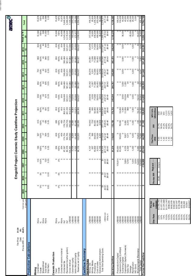
Appendix F
Cash Flow Model
| | | |
Project No. 146357 | TOC vii |
|
November 2004 | |
| IDAHO-MARYLAND MINING CORPORATION |
PRELIMINARY ASSESSMENT TECHNICAL REPORT IDAHO-MARYLAND MINE, GRASS VALLEY, CALIFORNIA |
1.0
SUMMARY
1.1
Introduction
The Idaho-Maryland Mining Corporation (Idaho-Maryland) is a wholly owned subsidiary of Emgold Mining Corporation (Emgold). Idaho-Maryland holds a mining lease and option to purchase the Idaho-Maryland property. The property encompasses a previously mined gold deposit suitable for further gold exploration and a recently defined industrial minerals deposit that may be suitable for the production of ceramic products. The Idaho-Maryland property is located near the eastern side of the City of Grass Valley, Nevada County, within the State of California.
The overall development plan for the Idaho-Maryland project envisions the following three major components:
1.
Development of a decline to access underground drill stations for gold exploration
2.
Construction of a commercial ceramics production facility which will utilize development rock from the decline and rock from an underground room-and-pillar mine as feed material
3.
Upon confirmation of an economic gold resource, establishment of a commercial gold mine and processing operation, integrated with the ceramics process so that gold process tailings and development rock would become the feedstock for the ceramic process
This technical assessment specifically evaluates the development of the decline plus the establishment of a stand-alone industrial minerals mine and ceramics production facility and describes further exploration potential for gold at the Idaho-Maryland project.
The establishment of a gold mine and processing operation is contingent on successful gold exploration. A stand-alone gold mine and process plant has been assessed in previous AMEC reports and is not specifically addressed in this Preliminary Assessment.
Previous work by Emgold focused on identifying and developing the gold resource at the property with the objective of establishing a commercial gold mine. Idaho-Maryland has stated that it plans to continue development of the gold resources and a significant underground gold exploration program is planned. The exploration program will require development of a long decline to access underground drill stations. In driving the decline, and if a commercial gold mining operation is ultimately established, Idaho-Maryland will not be able to obtain sufficient nearby land holdings to construct both a long-term waste rock and tailings storage facility. Operations will eventually entail disposal of waste material off
| | | |
Project No. 146357 | Page 1-1 |
|
November 2004 | |
| IDAHO-MARYLAND MINING CORPORATION |
PRELIMINARY ASSESSMENT TECHNICAL REPORT IDAHO-MARYLAND MINE, GRASS VALLEY, CALIFORNIA |
site. The permitting, logistics and financial effects caused by ongoing off-site waste disposal will likely impact the project to the extent that it may no longer be feasible. In response to this, Idaho-Maryland management identified and licensed a new technology that offers the potential to utilize the development rock and gold process tailings for the production of ceramic building products. The trade name for the technology is Ceramext™. The Ceramext™ process is a new, patented, and proprietary process for the manufacture of ceramic products. The process has been tested at the lab and pilot-plant scale currently, there are no full-scale commercial operations utilizing the process. Implications for scale-up to commercial application, including technical and economic parameters, are still to be determined. Larg e domestic and international markets exist for quality ceramics products, but acceptance of Ceramext™ ceramic products will ultimately depend on quality and price. Successful application of the Ceramext™ technology is projected to consume all the mine waste rock and process tailings thereby eliminating the requirement for long-term surface storage of these materials.
The successful production and sales of ceramic materials would allow Idaho-Maryland to continue with exploration of additional gold targets, then pre-production development, with the objective to define an economic gold reserve while generating positive cash flow from the ceramics production.
1.2
Geology and Mineral Resource
1.2.1
Geological Setting
The Idaho-Maryland mine and the Grass Valley Mining District are situated in the northern portion of the Sierra Nevada Foothills Gold Belt. This belt averages 50 miles in width and extends for 320 miles in a north-northwest orientation along the western slope of the Sierra Nevada range. The extent of the Sierra Nevada Foothills Gold Belt coincides closely with the outcrop area of the Sierra Nevada Foothills Metamorphic Belt.
The rocks underlying the Idaho-Maryland mine property are divisible into five separate units ranging in age from early to late Jurassic:
1.
Early Jurassic meta-sediments of the Fiddle Creek Complex
2.
Early Jurassic meta-volcanics and interflow sediments of the Lake Combie Complex
3.
Middle Jurassic ophiolitic assemblage of the Spring Hill Tectonic Mélange
4.
Discontinuous later Jurassic Tectonic Mélange of the Weimar Fault Zone
5.
Late Jurassic dioritic intrusives.
| | | |
Project No. 146357 | Page 1-2 |
|
November 2004 | |
| IDAHO-MARYLAND MINING CORPORATION |
PRELIMINARY ASSESSMENT TECHNICAL REPORT IDAHO-MARYLAND MINE, GRASS VALLEY, CALIFORNIA |
The most important of these units with respect to the feed material for the ceramics manufacturing process are the Jurassic meta-volcanics. With regard to exploration for gold mineralization, the Spring Hill Tectonic mélange is the unit of primary interest.
The Idaho-Maryland property hosts a structurally controlled deformation zone terminated at its eastern end by a regional fault. Within this deformation corridor, large dismembered clasts of predominantly ophiolitic igneous origin are present in a foliated serpentinite melange matrix. These large clasts are referred to as slabs in Idaho-Maryland company reports. Identified slabs consist of albitized (sausserite) meta-gabbro, massive antigorite serpentinite, meta-diabase, meta-diorite, slates, and basaltic to dacitic meta-volcanics.
The largest slab of metavolcanic rocks on the property is the Brunswick Slab, which is 1.5 miles in length, approximately 0.6 miles in width, elongated in an eastward direction, and open at depth. This slab is interpreted to be derived from the Lake Combie Complex, and the industrial minerals resource is a block within this slab.
The industrial minerals feedstock deposit consists mostly of metamorphosed andesite, dacite, diabase and gabbro correlative with the Lake Combie Complex. These rocks were observed in drill core and outcropping on the surface as well.
1.2.2
Summary of Industrial Mineral Resource (Ceramics Feedstock)
The industrial minerals ceramics feedstock resource was delineated by seven geotechnical core holes drilled at inclinations of 40° and 45°, one exploration core hole, seven surface sample sites, and certain geologic data from historical underground mine drifts. The top boundary of the resource is 200 ft below the ground surface (due to depth of mineral rights). Drill hole spacing ranged from 80 ft to 1,200 ft. The lower boundary of the resource is based on the bottom of the drill holes, since drilling ended within Lake Combie Complex igneous rock units. The west boundary is where the amount of gabbro and ultramafic rocks begin to increase. The east boundary is based on the limit of geotechnical drilling and surface sampling.
The Idaho-Maryland project has measured, indicated, and inferred industrial minerals (ceramics) feedstock resources, as summarized in Table 1-1.
| | | |
Project No. 146357 | Page 1-3 |
|
November 2004 | |
| IDAHO-MARYLAND MINING CORPORATION |
PRELIMINARY ASSESSMENT TECHNICAL REPORT IDAHO-MARYLAND MINE, GRASS VALLEY, CALIFORNIA |
Table 1-1:
Summary of Ceramics Feedstock Resources, 5 November 2004
Classification | Tons |
Measured mineral resources | 48,817,000 |
Indicated mineral resources | 122,685,000 |
Measured + Indicated mineral resources | 171,502,000 |
Inferred mineral resources | 358,112,000 |
1.2.3
Gold Resource
The Idaho-Maryland property hosts a significant gold deposit first discovered in 1851. Gold mining commenced in 1862 and continued until 1954. The Idaho-Maryland was the second largest underground gold producer in California.
The varying styles of mineralization present at the Idaho-Maryland project are typical of those commonly found in mesothermal lode gold deposits worldwide. At least four basic types of mineralization have been recognized to contain significant gold deposits. In order of importance these include: 1) gold-quartz veins, 2) mineralized black slate bodies, 3) mineralized diabasic slabs, and 4) altered, mineralized phyllonites. The veins consist primarily of quartz, which is milky white, massive to banded, sheared, and brecciated. Gold occurs as native gold, ranging from very fine grains within the quartz to leaves or sheets along fractures.
Table 1-2:
Gold Resources, 20 September 2004
| | True Thickness
(ft) | Tonnage
(tons) | Gold Grade
(oz/ton) | Gold
(oz) | Gold Grade
(oz/ton)
1.44 MCF | Gold
(oz)
1.44 MCF1 |
Idaho-Maryland Project 2 |
|
| |
| |
|
Measured Mineral Resource 1 | 13.3 | 271,000 | 0.22 | 59,000 | 0.31 | 85,000 |
Measured Mineral Resource 2 | 70.7 | 831,000 | 0.15 | 127,000 | 0.15 | 127,000 |
Indicated Mineral Resource | 8.1 | 489,000 | 0.35 | 172,000 | 0.50 | 243,000 |
Measured + Indicated Mineral Resources | 41.1 | 1,666,000 | 0.22 | 375,000 | 0.28 | 472,000 |
Inferred Mineral Resources | 9.3 | 2,526,000 | 0.26 | 666,000 | 0.38 | 952,000 |
1. MCF = Mine Call Factor (not applicable to Waterman Group resources). 2. Idaho-Maryland measured resources are split into two categories: 1. the Eureka, Idaho, Dorsey, and Brunswick Groups, and 2. the Waterman Group (stockwork/slate type ore).
1.3
Exploration
1.3.1
Industrial Minerals Resource Exploration
Emgold, initiated exploration of the Idaho-Maryland property in 1993. Emgold’s wholly owned subsidiary, Idaho-Maryland has continued exploration to the present. The primary
| | | |
Project No. 146357 | Page 1-4 |
|
November 2004 | |
| IDAHO-MARYLAND MINING CORPORATION |
PRELIMINARY ASSESSMENT TECHNICAL REPORT IDAHO-MARYLAND MINE, GRASS VALLEY, CALIFORNIA |
focus has been to identify gold mineralization with the objective of developing a mineable gold resource.
More recently, Emgold identified and secured rights to a new potentially commercial ceramics manufacturing process and realized that the Idaho-Maryland property may host mineral resources suitable as feedstock for the process. Initial investigations of the meta-volcanic rock were begun in June 2004 with a geotechnical drilling program designed to obtain data for the design of a mine access ramp. Geological information from this program was also analyzed to determine if the rock excavated during ramp construction would be suitable feedstock for the ceramics process. The analysis included surface geologic mapping, outcrop sampling, sampling of the diamond drill core, and testing of samples to assess their suitability for ceramics manufacture. The result of these analyses was the definition of a large volume of igneous rocks of similar composit ion that were considered satisfactory as an industrial mineral resource suitable for ceramics manufacture.
The industrial rock resource is adequately defined by core drilling, but further testing, marketing, and production of ceramic products using the Ceramext™ Process, and the beginning of underground development will be necessary to upgrade industrial rock resources into reserves. No further core drilling of the meta-volcanics is planned until access is developed underground.
1.3.2
Gold Exploration
The gold exploration program has consisted of an extensive geologic evaluation of the historical mine records plus additional diamond drilling from surface. This rather unique program was possible because of the excellent and comprehensive preservation of the historical Idaho-Maryland mine and mill records. Idaho-Maryland has indicated this data is exhaustive and essentially complete, and was used to generate a consistent, property-wide structural geology model and vein set definition and chronology. Unmined mineralization was identified along underground workings and in historical diamond drill holes. Interpretation of the updated geologic model defined new vein sets and extensions of known vein sets. These were categorized for mineral resource estimates, future exploration, and expansion.
There is potential to identify additional gold resources on the Idaho-Maryland property, and Idaho-Maryland management has indicated its intent to continue with an ongoing gold exploration program. An access ramp is planned to establish underground drilling stations for further drill testing of key gold target areas, plus definition and expansion of known gold resources.
| | | |
Project No. 146357 | Page 1-5 |
|
November 2004 | |
| IDAHO-MARYLAND MINING CORPORATION |
PRELIMINARY ASSESSMENT TECHNICAL REPORT IDAHO-MARYLAND MINE, GRASS VALLEY, CALIFORNIA |
1.4
Property Description and Tenure
The Idaho-Maryland property is 1.5 miles from the center of Grass Valley, Nevada County, in north-central California. The property comprises approximately 2,750 acres of mineral lands, with 37 acres of surface rights centered around the New Brunswick shaft, 101 acres of surface rights west of the Idaho shaft, and a one-acre easement on the Round Hole Shaft property. The 101 acre site is called the Idaho-Maryland property. The mineral rights are defined as sub-parcels in a Quit Claim Deed. The mineral rights are restricted to a variable depth from surface and are generally contiguous below 200 ft from surface. Idaho-Maryland has an agreement with the mineral rights holders (BET Group) that include a mining lease and an option to purchase both the 56 and 37 acre properties. The term of the lease agreement is five years commen cing 1 June 2002. During the term of the lease agreement, any production from the property will be subject to a 3% Net Smelter Royalty (NSR).
1.5
Mining
An underground mine plan has been developed to extract the industrial minerals resource at the Idaho-Maryland mine using modern mining methods and simultaneously provide access to underground gold exploration targets and known gold resources.
Feed material for ceramics production will come primarily from room-and-pillar stopes located 500 ft or more below surface. The decline and ancillary development will also provide ceramic feed material. The decline has been placed such that it will also provide an excellent drill platform for exploration of the known gold resources and additional exploration targets within and adjacent to the historic Idaho-Maryland workings.
The ramp access will be driven as two declines separated by a 60 ft pillar. This will allow one decline to be used for fresh air and the other for exhaust, providing ample ventilation without the need for a major ventilation raise until a connection can be established with the Brunswick mine workings.
To reduce the potential for higher noise levels on surface, a temporary crusher for ceramic feed material and development rock will be installed underground at 1,000 ft from the portal and within a year after portal excavation begins. Until this time, movement of trucks and crushing of ceramic feed material on surface will be confined mostly to daylight hours.
The temporary crusher will supply the surface stockpiles until a permanent crusher can be located at greater depth. The permanent crushing installation will be operational roughly three years after the start of the decline at a depth of 900 ft below surface. Like the temporary crusher, it will supply surface stockpiles via a 36" conveyor. Also, in
| | | |
Project No. 146357 | Page 1-6 |
|
November 2004 | |
| IDAHO-MARYLAND MINING CORPORATION |
PRELIMINARY ASSESSMENT TECHNICAL REPORT IDAHO-MARYLAND MINE, GRASS VALLEY, CALIFORNIA |
consideration of noise levels on surface, the underground coarse ore bin and crusher have been sized to supply full production feed operating one shift per day.
Ground conditions in the area of the ceramics feedstock resource are expected to be very good. Room-and-pillar mining has been selected as the long-term mining method because it is responsive to changes in ground conditions, and the equipment and workforce requirements are similar to those for tunneling. The method is based on personnel entry so the underground openings will be smaller than with other bulk mining methods.
No backfill is planned after extraction of the ceramics feedstock/industrial minerals resource. Pillars have therefore been designed with high safety factors, and recovery is planned at roughly 25% of the resource. Rock pillars have been designed to remain stable indefinitely.
Room-and-pillar mining for ceramic plant feed may start at 500 ft below surface roughly three years after the start of the underground decline. By this time, the permanent crushing and conveying installation will be operational. Ceramics production is scheduled to ramp up gradually from 1,200 ton/d to 2,400 ton/d over the course of three years from initial plant start up.
The dewatering of the mine workings from the New Brunswick Shaft will be required to eliminate the risk of water pressure transmitted through diamond drill holes penetrating areas close to the old mine workings and will be required in advance of a breakthrough into old mine workings.
Surface exposure of underground workings will be limited to the portal, which will be covered with a culvert and four raises for ventilation and emergency exit from the mine.
1.6
Process
1.6.1
Mineral Processing
The development scenario for the Idaho-Maryland ceramics project will see an initial production rate of 1,200 ton/d, increasing to 2,400 ton/d at the start of Year 4 after initial plant start-up.
1.6.2
Crushing, Drying, and Grinding
The feed material for the ceramic production will consist primarily of meta-volcanics. Run-of-mine (ROM) ceramics plant feed material will be crushed in an underground crusher and conveyed to two crushed material stockpiles on surface adjacent to the process plant. Crushed ore will be drawn from the stockpiles by reclaim feeders and fed to the
| | | |
Project No. 146357 | Page 1-7 |
|
November 2004 | |
| IDAHO-MARYLAND MINING CORPORATION |
PRELIMINARY ASSESSMENT TECHNICAL REPORT IDAHO-MARYLAND MINE, GRASS VALLEY, CALIFORNIA |
secondary/tertiary crushing plant. Crushing circuit product will then be passed through a rotary kiln drier to reduce the moisture content to 1% prior to a single stage of grinding in a high-pressure-grinding roll (HPGR). The ground product will be classified in a dynamic separator with a target final product particle size of 80% passing 150 µm. The sized product will be conveyed to a series of storage silos adjacent to the ceramics plant and will be segregated depending on the mineralogical composition and the final ceramic product required.
Although the initial Phase 1 ceramic plant capacity will be 1,200 ton/d, the secondary and tertiary crushing circuit will be constructed with a capacity of 2,400 ton/d, which will be sufficient for Phase 2 ceramic production rate. The initial high-pressure grinding roll will have a capacity of 1,200 ton/d, and a second grinding roll circuit will be installed for the expansion to 2,400 ton/d. Primary underground crushing and conveyor transport to the surface stockpile will take place on dayshift only to minimize noise levels during non-daylight hours. The secondary/tertiary crushing and grinding circuits will be completely enclosed in an insulated building to minimize external noise levels. This will permit these circuits to operate 24 h/d.
1.6.3
Ceramics Production
Ceramics manufacturing will utilize the proprietary Ceramext™ process, which is based on high temperature vacuum extrusion to produce high-strength, low porosity industrial ceramics such as floor tile, roof tile, brick, and other construction materials. Ceramic feed material will be drawn from the silos and conveyed to a set of blenders used to mix predetermined quantities of feed material for different end products. From the blenders, the feed material will be conveyed to screw feeders used to meter feed material to a bank of pre-heaters. Each pre-heater will feed multiple ceramic manufacturing lines and will serve to drive off remaining moisture as well as heating the material for the ceramics process. Upon exiting the pre-heaters, the material will be fed into the extrusion and forming process. From t he extrusion and forming process, the shaped pieces will be directed to a glazing process or to the cooling furnaces. The cooling furnaces provide a controlled temperature environment to reduce the ceramic product to ambient temperature.
From the cooling furnaces, products will be machine stacked. Flat tile products will be boxed, strapped, and palletized. Shaped tile products, brick pavers, and block will be strapped and palletized. All packaging operations will be fully automated. Packaged products will be delivered to either indoor or outdoor storage to await customer delivery. The Ceramext™ equipment is patented, the process patent is pending and additional patents are being prepared for further protection and commercialization of the intellectual property. A copy of the patent is in Appendix A. The Ceramext™ process has been successfully tested at the pilot plant level. However, at this point, there is no full-scale production unit in operation.
| | | |
Project No. 146357 | Page 1-8 |
|
November 2004 | |
| IDAHO-MARYLAND MINING CORPORATION |
PRELIMINARY ASSESSMENT TECHNICAL REPORT IDAHO-MARYLAND MINE, GRASS VALLEY, CALIFORNIA |
Dr. Carl Frahme, an independent consultant and the designated Qualified Person for the ceramic portion of the project, has evaluated the technical and economic aspects of the Ceramext™ project. He has concluded that the Ceramext™ process is technologically sound, that its basic premise of high temperature extrusion has been validated and demonstrated, and that production of competitive ceramic has the potential to be feasible. His economic evaluation indicates that the process may achieve lower production costs and produce superior products when compared to existing technology currently in use, and is economically attractive and viable. He also evaluated the market for products that could be produced by the process, and has determined that the markets are large and that market entry and penetration do not offer large obstacles.
1.6.4
Gold Processing (Future)
Should a commercial gold resource ultimately be defined, the crushing and grinding circuits installed for the ceramics process will also serve to crush and grind ore for the gold recovery process. Furthermore, the overall process route would be modified so that the product from the grinding circuit would report first to the gold recovery circuit. The final process tails from the gold circuit would then be treated to remove residual cyanide, dewatered, dried, and then fed to the ceramics process.
The gold ore would be crushed and then ground to 80% passing 150 µm particle size. Gravity concentration and flotation circuits would be used to produce gold concentrates. The concentrates would be leached in an intensive cyanidation circuit to extract gold, and the gold would be recovered from the leach solutions by precipitation in an electrowinning circuit. The gold would be smelted on site to produce doré, which would then be transported off-site to a custom refiner to produce refined bullion. Barren solid residue from the intensive leach process would be rinsed to remove residual cyanide, and then transported off site to a custom treatment facility.
Tailings from the process plant would be dewatered to recover water for reuse in the process. All material that has come into contact with cyanide would be treated to destroy any remaining cyanide. Dewatered tailings material in excess of that required for backfill in the gold mine would be used for ceramics production.
As the process tailings would be consumed in the ceramics manufacturing process or used for backfill in the underground mine, there would be no need for a surface tailings containment system.
1.7
Site Facilities
The Idaho-Maryland project consists of three general areas: the 101 acre Idaho-Maryland site property adjacent to the Idaho shaft, the 37 acre Brunswick property surrounding the
| | | |
Project No. 146357 | Page 1-9 |
|
November 2004 | |
| IDAHO-MARYLAND MINING CORPORATION |
PRELIMINARY ASSESSMENT TECHNICAL REPORT IDAHO-MARYLAND MINE, GRASS VALLEY, CALIFORNIA |
New Brunswick shaft, and the 1 (one) acre easement on the Round Hole Shaft property. The bulk of the new facilities will be constructed on the Idaho-Maryland property. These facilities will include the decline portal, vent raise, escape raise, ore stockpiles, storm water detention and mine water sedimentation ponds, process plants, warehouse, truck shop, electrical substation, mine dry, administration building and visitors center.
It is planned to construct certain facilities on the Brunswick property as part of the proposed gold exploration program. These facilities will include hoist house, headframe and hoist, pump system for mine dewatering, mine water treatment system, power supply substation and emergency generator/compressor house.
The Round Hole shaft may be used in the future as a ventilation shaft and emergency access shaft.
The proposed location of the decline portal is toward the west side of the Idaho-Maryland property. Services feeding the decline will be electric power, fresh water, discharge water, communications lines, and compressed air pipelines. The escape raise will be positioned in the southeast corner of the Idaho-Maryland property, and the ventilation shaft will be located in the northeast corner.
A high voltage powerline located within a quarter mile of the Idaho property will supply the site with power. The average power demand for the mine, ceramics manufacturing plant and ancillary facilities will be approximately 9200 kW at the 1,200 ton/d production rate. At the increased production rate of 2,400 ton/d the power demand will increase to 18,500 kW. Natural gas for the rotary kilns and ceramics process heating will be supplied via a pipeline to the site.
Fresh water will be supplied from the Nevada Irrigation District (NID) water supply. Process water will be drawn as reclaim water from the mine dewatering system.
The existing mine workings will be dewatered via a pumping system in the New Brunswick shaft. The water will be treated to remove dissolved iron and manganese and any other metals, and will meet state and federal water quality standards prior to release to the South Fork Wolf Creek. Iron and manganese residues recovered during water treatment will be collected for recycle to the ceramics process.
Other metal residues, if present, will be collected and transported off-site for treatment and/or storage.
| | | |
Project No. 146357 | Page 1-10 |
|
November 2004 | |
| IDAHO-MARYLAND MINING CORPORATION |
PRELIMINARY ASSESSMENT TECHNICAL REPORT IDAHO-MARYLAND MINE, GRASS VALLEY, CALIFORNIA |
1.8
Permit Application Requirements and Status
A Conditional Mine Use Permit (use permit) is required in order for Idaho-Maryland to continue with the underground exploration, and development of the Idaho-Maryland deposit.
Emgold through its subsidiary, Idaho-Maryland Mining Corporation has been successful in obtaining all permits applied for to date regarding the exploration and development of the Idaho-Maryland project. Idaho-Maryland is currently preparing separate applications for permits to further exploration, development and operation of the mine.
Idaho-Maryland is currently applying for a use permit to conduct another surface core drilling exploration program. Surface exploration programs have and will continue to consist of diamond drilling to expand the understanding of the project geology and identify underground exploration targets. Separate drilling permits will be required to conduct the surface exploration drilling programs.
A use permit will be required to conduct the underground diamond drilling exploration and mine development programs. This use permit will also include the construction of the decline, dewatering of existing mine workings, mine development, construction of surface facilities including processing and support facilities, and ultimately closure and reclamation activities. The application for the use permit will incorporate a phased development program in order to streamline the permitting process while at the same time, retaining the option to evaluate the project on completion of underground drilling and exploration activities. If the results from both the surface and underground exploration meets expectations, Idaho-Maryland may proceed with further development, production and operation under the same use permit.
Granting of the use permit for the mineral resource development program will require a zoning designation and general plan amendment from the City of Grass Valley to allow for mining operations. Such actions require a use permit application be submitted to the lead agency, which will trigger the California Environmental Quality Act (CEQA) process.
In addition to CEQA, the following environmental laws are applicable to the project: Surface Mining and Reclamation Act (SMARA, 1975), Clean Water Act (CWA, 1972), and Clean Air Act (CAA, 1972).
Idaho-Maryland commissioned MACTEC Engineering and Consulting, Inc. (MACTEC) of Petaluma, California, to complete a Conceptual Development Review Application for the Idaho-Maryland mine project. This document was completed on 28 July 2004 and has been received by Idaho-Maryland management. This document was submitted to the City of Grass Valley on 30 July 2004. An initial response from the City of Grass Valley has
| | | |
Project No. 146357 | Page 1-11 |
|
November 2004 | |
| IDAHO-MARYLAND MINING CORPORATION |
PRELIMINARY ASSESSMENT TECHNICAL REPORT IDAHO-MARYLAND MINE, GRASS VALLEY, CALIFORNIA |
been received by Idaho-Maryland and Idaho-Maryland is now preparing the final conditional mine use permit application for submission to the City of Grass Valley.
1.9
Environmental Considerations
Idaho-Maryland contracted MACTEC to complete a Phase 1 Environmental Site Assessment of the WestBet property (also referred to as the Idaho-Maryland). The investigation did not identify evidence of recognized environmental conditions. A due diligence site investigation was completed by MACTEC on the adjoining Brenner property (formerly known as the Lausman) and evidence of recognized environmental conditions was observed. The environmental concerns on the Lausman property relate to a log pond and an underground fuel storage tank. Subsequent to the performance of the investigation, Idaho-Maryland purchased the property under a joint venture agreement with Milco Development. Under the terms of the agreement, Idaho-Maryland owns the southern 45 acres of the 67 acre property and Milco owns the remaining portion. The log pond is locat ed entirely on the Milco property. The underground fuel storage is located entirely on the Idaho-Maryland property. Remediation of the underground fuel storage is currently underway.
The Phase I Environmental Site Assessment is preliminary in scope and MACTEC recommends more detailed assessment including testing on samples of soil and groundwater.
Virtually all of the building structures related to the historic mine operations on the Idaho-Maryland property have been removed. The only physical structures remaining are two concrete towers previously used for the deposition of mine tailings. Idaho-Maryland management has stated that the company may be responsible for any environmental liabilities pertaining to the former mine operations.
Due to its proximity to the City of Grass Valley, the proposed design has taken into consideration noise levels generated by the operation. During the initial development of the underground mine access, haul trucks will transport rock to a temporary primary crusher on surface for a period of approximately one year. Hauling and crushing activities will be restricted to daylight hours during this period. The primary crusher will be relocated underground and a conveyor installed once sufficient mine development has been completed. Conveying of rock to surface will be conducted only during daylight hours.
Once the surface plant facilities are constructed, most of the industrial operations with the exception of the crushed rock stockpiles will be housed within fully enclosed and insulated buildings. This will serve to maintain low external noise levels. As the mine is underground, virtually all mine-related operations will be underground and noise will not be a factor.
| | | |
Project No. 146357 | Page 1-12 |
|
November 2004 | |
| IDAHO-MARYLAND MINING CORPORATION |
PRELIMINARY ASSESSMENT TECHNICAL REPORT IDAHO-MARYLAND MINE, GRASS VALLEY, CALIFORNIA |
Significant effort will be made to minimize the physical and visual impact of the project on the environment and community. Existing waterways will be preserved. Impact on existing vegetation will be minimized. Current architectural codes will be strictly adhered to. Visual sight lines will be taken into account in the layout of the project site. Surface exposure of underground workings will be limited to the portal, which will be covered with a culvert, and four raises required for ventilation and emergency exit from the mine.
1.10
Marketing and Sales Approach
Based on the 1,200 ton/d feed rate, the ceramics plant could produce approximately 160 Mft2/yr of tile. This represents approximately 5% of 2003 US tile consumption and 35% of 2003 California consumption. The second stage of mine development would double this production level to approximately 320 Mft2/yr.
Given the superior properties of tile and other products expected using Ceramext™ technology, the proposed market strategy would be to compete in the higher ends of the marketplace. For ceramic tile, this would include vitrified floor tile and porcelain tile products. These products command higher retail prices and represent the major share of the market growth in recent years. Target markets would include large commercial projects (malls, commercial office space, restaurants, civic projects) and upscale home floor, wall, and countertop installations, for both new construction and renovation. Factory selling prices in the $1.00/ft2 to $1.50/ft2 are expected based on current market experience.
A number of marketing and sales channels are available, including factory direct showrooms, independent distributors, and large retail stores. An assessment of the marketing channels is warranted to identify the optimum marketing and sales approach.
1.11
Capital Cost Estimate
The estimated capital cost for development of the mining, process, and ancillary facilities to achieve a production rate of 1,200 ton/d is $195,914,000. The estimated additional capital cost for the expansion of the mine and process plant to achieve a production rate of 2,400 ton/d is $154,652,000. The total estimated mine and plant capital cost is $350,566,000. The costs are based on 4th quarter 2004 US dollars. The estimate should be considered as conceptual with a probable accuracy of ±35%.
The capital cost estimate includes:
| | | |
Project No. 146357 | Page 1-13 |
|
November 2004 | |
| IDAHO-MARYLAND MINING CORPORATION |
PRELIMINARY ASSESSMENT TECHNICAL REPORT IDAHO-MARYLAND MINE, GRASS VALLEY, CALIFORNIA |
contingency
Owner’s costs
working capital.
Separate from the ceramic mine and plant project cost, an additional $43,000,000 has been included to complete dewatering and rehabilitation of the Brunswick mine workings, and to perform a gold exploration program primarily in the areas of the previous Brunswick and Idaho-Maryland workings, and complete a feasibility study on the gold project.
The total project capital cost including mine, plant, mine dewatering, rehabilitation of existing Idaho-Maryland mine workings, and gold exploration program is $393,566,000.
1.12
Operating Cost Estimate
The estimated project operating costs are presented in Tables 1-3 and 1-4. The mine operating costs are based on unit costs and manpower levels typical of other underground mines of similar scope with the notable exception that access drives provide feed to the process plant and therefore the cost per ton is much lower. The processing costs are comprised of two major components; 1) crushing, drying, and grinding; 2) ceramics processing. The crushing, drying, and grinding costs are based on typical industry costs for plants of similar scope. The ceramics processing costs have been provided by Idaho-Maryland and must be considered conceptual, as there are no plants in operation using this technology on which to base the estimated costs. The G&A costs have been based on other mining projects of similar size.
| | | |
Project No. 146357 | Page 1-14 |
|
November 2004 | |
| IDAHO-MARYLAND MINING CORPORATION |
PRELIMINARY ASSESSMENT TECHNICAL REPORT IDAHO-MARYLAND MINE, GRASS VALLEY, CALIFORNIA |
Table 1-3:
Operating Costs by Year $/ton of Feed Processed
| Pre-Production | | Expansion | | Full Production |
| Year 1 | Year 2 Q1 + Q2 | | Year 2 Q3 + Q4 | Year 3 | Year 4 | Year 5 Q1 + Q2 | | Year 5 Q3 + Q4 | Year 6 | Year 7 | Year 8 | Year 9 | Year 10 |
Tons/d | | | | 1,200 t * | 1,200 t * | 1,200 t * | 1,200 t * | | 2,400 t * | 2,400 t | 2,400 t | 2,400 t | 2,400 t | 2,400 t |
Mining | - | - | | 20.28 | 28.87 | 34.90 | 40.93 | | 26.10 | 30.21 | 30.81 | 29.68 | 30.09 | 28.75 |
Process | - | - | | 97.07 | 97.07 | 97.07 | 97.07 | | 90.22 | 88.22 | 88.22 | 88.22 | 88.22 | 88.22 |
G&A | - | - | | 7.01 | 7.01 | 7.01 | 7.01 | | 3.50 | 3.50 | 3.50 | 3.50 | 3.50 | 3.50 |
Total | - | - | | 124.36 | 132.95 | 139.97 | 145.01 | | 119.82 | 121.93 | 122.53 | 121.40 | 121.81 | 120.47 |
* plant feed is combination of mined production and temporary stockpile reclaim
Table 1-4:
Operating Costs by Year $/ft2 of Ceramic Product
| Pre-Production | | Expansion | | Full Production |
| Year 1 | Year 2 Q1 + Q2 | | Year 2 Q3 + Q4 | Year 3 | Year 4 | Year 5 Q1 + Q2 | | Year 5 Q3 + Q4 | Year 6 | Year 7 | Year 8 | Year 9 | Year 10 |
Tile production | | 160,754,000 ft²/yr | | 321,507,000 ft²/yr |
Mining | - | - | | 0.05 | 0.07 | 0.09 | 0.10 | | 0.07 | 0.08 | 0.08 | 0.08 | 0.08 | 0.08 |
Process | -
| - | | 0.25 | 0.25 | 0.25 | 0.25 | | 0.23 | 0.22 | 0.22 | 0.22 | 0.22 | 0.22 |
G&A | -
| - | | 0.02 | 0.02 | 0.02 | 0.02 | | 0.01 | 0.01 | 0.01 | 0.01 | 0.01 | 0.01 |
Total | - | - | | 0.32 | 0.34 | 0.36 | 0.37 | | 0.31 | 0.31 | 0.31 | 0.31 | 0.31 | 0.31 |
| | | |
Project No. 146357 | Page 1-15 |
|
November 2004 | |
| IDAHO-MARYLAND MINING CORPORATION |
PRELIMINARY ASSESSMENT TECHNICAL REPORT IDAHO-MARYLAND MINE, GRASS VALLEY, CALIFORNIA |
1.13
Financial Analysis
The preliminary financial analysis for this project is presented in Tables 1-5 and 1-6. Based on the parameters and assumptions incorporated into this assessment, the analysis indicates a positive financial return on this project. California sales tax has been included in the analysis.
The inputs to the model were generated by AMEC and Idaho-Maryland to a scoping study level of accuracy. The model used a discounted cash flow (DCF) analysis to determine the pre-tax net present value (NPV) and the pre-tax internal rate of return (IRR) for the project.
Table 1-5:
Scenario A NPV at Varying Discount Rates and IRR)
| | 0% | 10% | 20% | 30% | 40% |
NPV (US$ ‘000) | 3,706,755 | 1,111,143 | 392,891 | 139,238 | 32,893 |
IRR (%) | 45.8 | - | - | - | - |
Table 1-6:
Idaho-Maryland Estimated Capital, Annual Production Costs and Sales at Average Conditions
Daily
Feed Rate
(ton/d) | Capital
Expense
(US$ M) | Estimated Tile
Production
(Mft2) | Projected
Sales1
(US$ M) | Production
Costs
(US$ M) | Direct Profit2
(US$ M) |
1,200 | 196 | 160 | 192 | 77 | 115 |
2,400 | 155 | 320 | 384 | 139 | 245 |
CA Sales Tax | 10 | - | - | - | - |
Total |
| - | - | - | - |
Note: 1 $1.30 ft2. 2 Excludes income taxes, dewatering and rehabilitation of existing Idaho-Maryland mine workings and gold exploration.
1.14
Project Schedule
The project schedule consists of five distinct stages: 1) securing permits and completion of feasibility study, 2) detail engineering, 3) driving of a decline to the industrial minerals mining area and development of initial mine excavation areas and exploration drill stations, 4) construction of the surface process and ancillary facilities, and 5) expansion of the mine production and surface process plant capacities.
Securing of permits and completion of a feasibility study is expected to require up to 24 months after submittal of the Conditional Mine Use Permit application. Detail engineering and development of the mine, construction of the surface plant and facilities is scheduled to require an additional 18 months. Overall, the implementation is estimated to be 36 to 42
| | | |
Project No. 146357 | Page 1-16 | ![[techreport054.gif]](https://capedge.com/proxy/20FR12G/0001137171-05-001000/techreport054.gif)
|
November 2004 | |
| IDAHO-MARYLAND MINING CORPORATION |
PRELIMINARY ASSESSMENT TECHNICAL REPORT IDAHO-MARYLAND MINE, GRASS VALLEY, CALIFORNIA |
months from submittal of the permit application to the start of production for the 1,200 ton/d project.
The expansion to 2,400 ton/d is projected to be completed 36 months after the initial start of the 1,200 ton/d processing plant.
1.15
Conclusions and Recommendations
This Preliminary Assessment Report was completed to assess at the conceptual level the economic potential to develop an industrial minerals mine and establish an associated ceramics production facility while providing underground access for gold exploration and resource definition. A key parameter to the viability of the project is the commercial application of the new, proprietary CeramextTM technology. The findings of this preliminary assessment are based entirely on the assumption that the technology may ultimately be successfully applied in a commercial application.
Recognizing the assumption and limitation stated above, the findings of the Preliminary Assessment indicate that the general concept of development of an industrial minerals mine and an associated ceramics production facility appears to warrant further development and study.
AMEC has identified a number of recommendations for this project. The recommendations are presented in Section 20.2.
| | | |
Project No. 146357 | Page 1-17 |
|
November 2004 | |
| IDAHO-MARYLAND MINING CORPORATION |
PRELIMINARY ASSESSMENT TECHNICAL REPORT IDAHO-MARYLAND MINE, GRASS VALLEY, CALIFORNIA |
2.0
INTRODUCTION AND TERMS OF REFERENCE
2.1
Introduction
Idaho-Maryland retained the services of AMEC Americas Limited (AMEC) to evaluate the potential of a ceramics project on the Idaho-Maryland property and to report the findings in a Preliminary Assessment report. AMEC has completed two previous evaluations of the property based on the gold mining potential. The first was an independent Qualified Person’s review and evaluation in the form of a Technical Report as defined in National Instrument 43-101, Standards of Disclosure for Mineral Projects in November 2002. The second was a Scoping Study, dated January 2003.
The overall development plan for the Idaho-Maryland project envisions the following three major components:
1.
Development of a decline to access underground drill stations for gold exploration
2.
Construction of a commercial ceramics production facility which will utilize development rock from the decline and rock from an underground room-and-pillar mine as initial feed material
3.
Upon delineation of an economic gold resource, establishment of a gold mining and processing operation, integrated with the ceramics process so that gold process tailings would combine with mine rock as the feedstock for the ceramic process
Previous work by Emgold focused on identifying and developing the gold resource at the property with the objective of establishing a commercial gold mine. Idaho-Maryland management plans to continue pursuing development of the gold resources through further surface and underground exploration; however, underground exploration can only proceed after a Conditional Mine Use Permit is received from the City of Grass Valley. Obtaining this permit depends on acceptance of the project by the City of Grass Valley and Nevada County. In the event of planning and establishing a mining operation, the satisfactory management and treatment of all development rock and tailings from any underground exploration, mining, and recovery process would be critical to this acceptance.
In response to this, Idaho-Maryland management identified and licensed a new technology that offers the potential to utilize the decline development rock and gold process tailings for the production of ceramic building products. The trade name for the technology is Ceramext™. Successful application of the Ceramext™ technology would see all the mine development rock and gold process tailings consumed thereby eliminating the requirement for long-term surface storage of these materials.
| | | |
Project No. 146357 | Page 2-1 |
|
November 2004 | |
| IDAHO-MARYLAND MINING CORPORATION |
PRELIMINARY ASSESSMENT TECHNICAL REPORT IDAHO-MARYLAND MINE, GRASS VALLEY, CALIFORNIA |
Upon identification of the Ceramext™ technology, Idaho-Maryland technical personnel also investigated the possibility of establishing a commercial industrial minerals mine on the Idaho-Maryland property. Their investigation led to the identification of a significant mineral deposit, the Brunswick Slab, within the Idaho-Maryland property boundaries that would provide suitable feed for the Ceramext™ process.
Application of the Ceramext™ technology combined with the suitability of the Brunswick Slab rock as feed material to the ceramics process may provide a business case for production of high-quality ceramic building materials. The successful production and sales of ceramic materials would allow Idaho-Maryland to continue with exploration, definition, and development of potential gold targets, with the objective to identify an economic gold reserve while generating positive cash flow from the ceramics development.
The industrial minerals mine will have an initial production rate of 1,200 ton/d, expanding in stages to an ultimate capacity of 2,400 ton/d by the end of the third year.
This study may be used to guide future work on the development of the project as well as to provide a development scenario for preparation of the use permit application. The study has been completed to a scoping level of accuracy. Facilities included in the scope are underground mine operations, a ceramics manufacturing facility, and ancillary plant and infrastructure.
Emgold through its wholly owned subsidiary, Golden Bear Ceramics Company, has signed an exclusive world-wide license agreement with Ceramext™, LLC to develop and use the Ceramext™ Process to convert mine development rock, tailings, waste and other naturally occurring materials into high quality ceramics. The Ceramext™ Process is a patented, energy-efficient, one-step technology capable of converting a wide variety of raw materials, including mine tailings and fly ash into high-strength, low-porosity, industrial ceramics such as floor tile, roof tile, brick, construction materials and other industrial and commercial products.
2.2
Terms of Reference
AMEC obtained information and data for the study from the Idaho-Maryland project site during visits between 3 and 11 October 2002, 3 and 4 June 2004, 24 August to 1 September 2004, and on 29 October 2004. Information was also obtained from a Scoping Study completed by AMEC in January 2003 for Emgold, which assessed the potential to establish a gold mining and processing operation. Additional information was obtained from Emgold’s head office in Vancouver, BC.
Idaho-Maryland and Emgold provided AMEC with the following information:
| | | |
Project No. 146357 | Page 2-2 |
|
November 2004 | |
| IDAHO-MARYLAND MINING CORPORATION |
PRELIMINARY ASSESSMENT TECHNICAL REPORT IDAHO-MARYLAND MINE, GRASS VALLEY, CALIFORNIA |
overall project scope
capital and operating costs for the Ceramext™ process and plant facilities
manpower level for the Ceramext™ manufacturing facility
general and administration (G&A) costs
property ownership and location details
historical and current gold resource and industrial minerals resource data
labor rates as determined by Western Compensation and Benefits Consultants.
Pertinent data were reviewed in sufficient detail for the preparation of this document. The following AMEC personnel provided Qualified Person review:
Sean Waller, M. Sc., P. Eng. Acted as study manager and provided input and/or review on crushing and grinding process design, capital and operating cost estimates relating to crushing, grinding, certain infrastructure and site services (Sections 16, Sections 19.3 to 19.5, and Sections 19.7.1 and 19.7.2). Mr. Waller has not visited the site.
Stephen Juras, Ph. D., P. Geol. Reviewed geologic data, mineralogy and resource estimates as well as sample handling protocols (Sections 7 – 13, Section 17). Dr. Juras also visited the site on 3 to 4 June 2004 and 29 October 2004 as part of this preliminary Assessment. Dr. Juras had previously visited the site during the period of 3 to 11 October 2002 as part of a previous Preliminary Assessment performed by AMEC.
Mr. Joe Ringwald, P. Eng. Reviewed the underground mine design and costs (Sections 19.1, 19.3, 19.4, and 19.7.1). Mr. Ringwald has not visited the site.
Additional Qualified Person assistance was provided by the following persons:
For all technical, financial and marketing information pertaining to the CeramextTM technology and process, and ceramics marketing, AMEC has relied on information supplied by Dr. Carl Frahme, Ph.D. (Sections 16.1.2,16.3.1, 19.3.3, 19.4.3, 19.7.2) AMEC understands Dr. Frahme is an independent consultant with recognized expertise in ceramics manufacture and marketing. Dr. Frahme is currently an independent consultant to Idaho-Maryland and Golden Bear Ceramics Company.
For environmental information pertaining to the project site, AMEC has relied on information supplied by Patricia Nelson, Thomas Graham and Matthew Walraven of MACTEC Engineering and Consulting, Inc. AMEC understands that Ms. Nelson, Mr. Graham and Mr. Walraven are suitably qualified environmental scientists and that MACTEC is a recognized consulting firm with expertise in the environmental sciences. Ms. Nelson visited the site on numerous occasions. Mr. Walraven visited the site on September 13, 2004 and Mr. Graham visited the site on 2 and 3 August 2004. (Section 4.0).
| | | |
Project No. 146357 | Page 2-3 |
|
November 2004 | |
| IDAHO-MARYLAND MINING CORPORATION |
PRELIMINARY ASSESSMENT TECHNICAL REPORT IDAHO-MARYLAND MINE, GRASS VALLEY, CALIFORNIA |
The CeramextTM process is a key parameter to the potential technical and economic viability of the project. This is a new, proprietary, patented process currently under development but at this point not proven in a commercial application. All information and data concerning the CeramextTM process were provided by Emgold, Idaho-Maryland management, and Dr. Carl Frahme, independent consultant of Emgold’s wholly owned subsidiary Golden Bear Ceramics Company.
Unless otherwise stated, all costs in this report are expressed in 4th quarter US dollars.
| | | |
Project No. 146357 | Page 2-4 |
|
November 2004 | |
| IDAHO-MARYLAND MINING CORPORATION |
PRELIMINARY ASSESSMENT TECHNICAL REPORT IDAHO-MARYLAND MINE, GRASS VALLEY, CALIFORNIA |
3.0
DISCLAIMER
The CeramextTM technology is a new, patented and proprietary technology. At this point, there are no commercial installations utilizing this technology. With regard to all aspects of the CeramextTM technology, Ceramext™ costing and ceramic products marketing, AMEC has relied on information provided by Dr. Carl Frahme, an independent consultant with specific expertise in ceramics manufacturing and marketing. AMEC has done so under the assumption that Dr. Frahme is a Qualified Person under NI 43-101 guidelines. Furthermore, AMEC has relied on information provided by Dr. Frahme for the definition of mineralogy suitable for processing with the CeramextTM technology.
For environmental information pertaining to the project site, AMEC has relied on information supplied by Patricia Nelson and Thomas Graham of MACTEC Engineering and Consulting, Inc. AMEC understands that Patricia Nelson and Thomas Graham are suitably qualified environmental scientists and that MACTEC is a recognized consulting firm with expertise in the environmental sciences.
AMEC also relied on a legal report entitled “Legal Title Opinion prepared for the Core Area Properties of the Idaho-Maryland Mine Project, Grass Valley Mining District, Nevada County, California” (Galati & Associates, 1997) for its review of title and mineral rights. The report was used based on the assumption it was prepared by a Qualified Person.
| | | |
Project No. 146357 | Page 3-1 |
|
November 2004 | |
| IDAHO-MARYLAND MINING CORPORATION |
PRELIMINARY ASSESSMENT TECHNICAL REPORT IDAHO-MARYLAND MINE, GRASS VALLEY, CALIFORNIA |
4.0
PROPERTY DESCRIPTION AND LOCATION
4.1
Location
The Idaho-Maryland project property is 1.5 miles east of the center of the City of Grass Valley, Nevada County, in the State of California (see Figures 4-1 and 4-2). The property lies primarily between the Idaho-Maryland Road, Brunswick Road, and State Route 174 and consists of approximately 2,750 acres of mineral lands, with 37 acres of surface rights centered around the New Brunswick shaft, and 101 acres of surface rights west of the Idaho shaft, and a one-acre easement on the Round Hole Shaft Property. The 101 acres of surface rights include a 56 acre parcel and an adjoining 45 acre parcel lying immediately to the east. The 56 and 45 acre sites are collectively called the Idaho-Maryland property. The mineral lands comprise portions of Sections 19, 29, 30, and 31 in T16N R9E and portions of Sections 23, 24, 25, 26, 36 in T16 N R8E. The site plan is shown on Dwg. 100-C-0005 in Appendix B.
The mineral rights are defined as sub-parcels in a Quit Claim Deed and are restricted to a variable depth from surface. In general, the rights are contiguous below 200 ft from surface. Emgold has an agreement with the mineral rights holders (BET Group) that include a mining lease and option to purchase the 101 and 37 acre properties. The term of the lease agreement is five years commencing on 1 June 2002. During the term of the lease agreement, any gold production from the property will be subject to a 3% Net Smelter Royalty (NSR). Idaho-Maryland owns the 45 acre parcel which comprises a portion of the 1001 acre site.
4.2
Jurisdictions
The Idaho-Maryland mine lands are located within the City of Grass Valley and in unincorporated county lands that are designated to be annexed into the city of Grass Valley by 2005. Other project lands, including the New Brunswick shaft, are on Nevada County lands, and are not part of any scheduled annexation. Certain administrative procedures will therefore need to be completed by the city to allow the project property to be developed for mineral extraction:
Such actions require a land use permit application be submitted to the Lead Agency, which will trigger the environmental assessment process required by the State of California as defined in the California Environmental Quality Act (CEQA). Other applicable state and federal environmental regulatory requirements are as outlined in Section 4.4.
| | | |
Project No. 146357 | Page 4-1 |
|
November 2004 | |
| IDAHO-MARYLAND MINING CORPORATION |
PRELIMINARY ASSESSMENT TECHNICAL REPORT IDAHO-MARYLAND MINE, GRASS VALLEY, CALIFORNIA |
Figure 4-1:
Project Location Map
![[techreport070.jpg]](https://capedge.com/proxy/20FR12G/0001137171-05-001000/techreport070.jpg)
| | | |
Project No. 146357 | Page 4-2 |
|
November 2004 | |
| IDAHO-MARYLAND MINING CORPORATION |
PRELIMINARY ASSESSMENT TECHNICAL REPORT IDAHO-MARYLAND MINE, GRASS VALLEY, CALIFORNIA |
Figure 4-2:
Mine Location Map
![[techreport073.jpg]](https://capedge.com/proxy/20FR12G/0001137171-05-001000/techreport073.jpg)
| | | |
Project No. 146357 | Page 4-3 |
|
November 2004 | |
| IDAHO-MARYLAND MINING CORPORATION |
PRELIMINARY ASSESSMENT TECHNICAL REPORT IDAHO-MARYLAND MINE, GRASS VALLEY, CALIFORNIA |
4.3
Permitting History
In the mid-1990s, Emperor Gold Corporation, the predecessor to Idaho-Maryland Mining Corporation, a subsidiary of Emgold, applied to the Nevada County Planning Department for a use permit to dewater and subsequently explore and sample the existing workings of the Idaho-Maryland mine. On 25 January 1996, the Nevada County Planning Department certified the Environmental Impact Report (EIR) prepared in accordance with CEQA and issued a conditional use permit. In accordance with the permit, the project was to have commenced by 25 January 1998 with completion of dewatering, exploration, and post-project activities by 25 January 2003.
To support dewatering activities, Emperor Gold applied for a National Pollution Elimination Discharge System (NPDES) permit with the California Regional Water Quality Control Board, Central Valley Region (CVRWQCB). On 3 May 1996, a permit was issued allowing Emperor to dewater the Idaho-Maryland mine. The permit was valid for a period of five years and expired on 3 May 2001.
Idaho-Maryland management submitted a “Conceptual Development Review Application” to the City of Grass Valley on 30 July 2004. The City of Grass Valley has reviewed the Conceptual Application and has identified where modification and/or additional information is required. Idaho-Maryland management is currently addressing the requirements for the formal Development Review Application.
The Development Review Application addresses the following items:
In addition, the application addresses the following issues.
Land Use
Required by the City of Grass Valley (City) and Nevada County (County)
Identifies the property boundaries, building locations and setbacks, parking spaces, and proposed land improvements. This information is relevant to the surface development required for the project.
| | | |
Project No. 146357 | Page 4-4 |
|
November 2004 | |
| IDAHO-MARYLAND MINING CORPORATION |
PRELIMINARY ASSESSMENT TECHNICAL REPORT IDAHO-MARYLAND MINE, GRASS VALLEY, CALIFORNIA |
General Plan Amendment
Required by the City and County
Describes changes (if any) to the General Plan, how the changes affect the existing policies of the General plan, or how new conditions or community desires warrant changes to the General Plan and how these changes relate to other elements of the General Plan. This information is relevant to the surface development required for the project.
Rezone/Pre-zone
Required by the City and County
Describes changes required to applicable zoning regulations and how they conform to the requirements of the General Plan. If General Plan Amendments are required, a description of how General Plan policies are being amended to meet the proposed changes to zoning designations is required. This information is relevant to the surface development required for the project.
Annexation
Required by the City and County
Describes current and proposed zoning and land use of the project site and adjacent properties, and provides a statement stating how the property is consistent with the City’s Sphere of influence and General Plan. This application must also describe proposed changes to service organizations (i.e., fire and police departments).
Surface Mining and Reclamation Act
An Exploration and Mining Use Permit is required by the City and County to conform to the requirements of the Surface Mining and Reclamation Act administered by the California Department of Conservation, Office of Mine Reclamation. The information developed for this permit application is particularly relevant to the subsurface development required for the project.
4.4
Environmental Laws
The following environmental laws are applicable to the proposed project: the California Environmental Quality Act (CEQA, 1970), Surface Mining and Reclamation Act (SMARA,
| | | |
Project No. 146357 | Page 4-5 |
|
November 2004 | |
| IDAHO-MARYLAND MINING CORPORATION |
PRELIMINARY ASSESSMENT TECHNICAL REPORT IDAHO-MARYLAND MINE, GRASS VALLEY, CALIFORNIA |
1975), Clean Water Act (CWA, 1972), and Clean Air Act (CAA, 1972). These laws, their respective purposes, and their applicability to the project are briefly described below.
California Environmental Quality Act
CEQA is regarded as the foundation of environmental law and policy in California. Its primary objectives are to disclose to decision-makers and the public the significant environmental effects of a proposed development and identify ways to avoid or reduce environmental damage.
Typically, when a Lead Agency is notified of a project, the CEQA process is initiated with consideration of the proposed project’s environmental characteristics. Because the proposed Idaho-Maryland project involves re-opening a mine that has been inactive for approximately 50 years, for which minimal reclamation, if any, has been performed, an Environmental Impact Report (EIR) will most likely be required under CEQA.
Surface Mining and Reclamation Act
SMARA was enacted to respond to the need for a continuing supply of mineral resources, while preventing damage from mining activities to public health, property, and the environment. The following activities are subject to SMARA: prospecting and exploratory activities, dredging and quarrying, streambed skimming, borrow pitting, and stockpiling of mined materials.
Mining may begin after the lead agency approves the mining permit and a plan for returning the land to a usable condition; this plan is referred to as a Reclamation Plan and is required for surface and subsurface mining operations. In addition, a prerequisite to mining activities is the applicant’s proof of financial assurances to guarantee costs of reclamation (e.g., surety bonds, irrevocable letters of credit, or trust funds).
Because the proposed project involves reopening a mine that has been inactive for approximately 50 years, for which minimal reclamation, if any, has been performed, a reclamation plan will need to be prepared for the project in accordance with SMARA. Reclamation plans are required for any exploration and mining related activities disturbing greater than 1,000 yd3; and/or more than 1 acre of land.
Clean Air Act
CAA was first passed to improve the air quality in the United States and has subsequently been amended to set limits on the discharges of certain pollutants.
| | | |
Project No. 146357 | Page 4-6 |
|
November 2004 | |
| IDAHO-MARYLAND MINING CORPORATION |
PRELIMINARY ASSESSMENT TECHNICAL REPORT IDAHO-MARYLAND MINE, GRASS VALLEY, CALIFORNIA |
The CAA includes a permit program for larger stationary or non-point sources that release pollutants into the air. These can include cars, trucks, other motor vehicles, consumer products, and machines used in industry.
Clean Water Act
CWA was enacted to restore and maintain the quality of US waterways.
The General Permit includes provisions for developing a Storm Water Pollution Prevention Plan (SWPPP) to maximize the potential benefits of pollution prevention and sediment and erosion control measures at construction sites.
In the case of the Idaho-Maryland project, the planned surface activities (exploratory mining and stockpiling) for areas greater than 1 acre will be subject to the NPDES (National Pollution Discharge Elimination System) and SWPPP processes to ensure they are performed in a manner that is protective of Wolf Creek.
Summary
Because exploratory activities and stockpiling of mined materials are envisioned for the project, these activities and the necessity to plan for the mine’s reclamation require that SMARA be addressed in the permitting and CEQA processes. The CWA and CAA issues can be fully addressed in the context of the CEQA analysis but may require that individual permits for certain mine operations be obtained from the administering agency. Because the proposed mine site is located between two reaches of Wolf Creek, the regulatory requirements for waste streams generated from the mine operations will focus on compliance with CAA and CWA.
4.5
Permit Requirements
Two aspects to the project need to be addressed in the permitting process: 1) those requirements for a surface exploratory phase that will facilitate definition of the mineral resources and 2) those requirements for development of the mineral resources combined with underground exploration and surface processing.
4.5.1
Permitting History
Idaho-Maryland has obtained permits previously for surface exploration drilling and for proposed underground exploration including the dewatering of historical mine workings. Table 4-1 shows these permits.
| | | |
Project No. 146357 | Page 4-7 |
|
November 2004 | |
| IDAHO-MARYLAND MINING CORPORATION |
PRELIMINARY ASSESSMENT TECHNICAL REPORT IDAHO-MARYLAND MINE, GRASS VALLEY, CALIFORNIA |
Table 4-1:
Permits
Permit | Lead Agency | Date of Permit |
Use Permit-Surface Drilling No. UP03-02 | City of Grass Valley | 21 May 2003 |
Conditional Use Permit No.U94-017 | County of Nevada | 26 January 1996 |
NPDES/Waste Discharge Requirements No. 96-098 | California Regional Water Quality Control Board | 3 May 1996 |
The use permit for the year 2003 surface drilling was subsequently extended for a six month time period by the City of Grass Valley. The year 1996 conditional use permit was approved for the dewatering and underground exploration of the historical Idaho-Maryland mine workings, and the NPDES/WDR permit was the dewatering permit issued by the State for that project. That dewatering/underground exploration project was not undertaken because of depressed commodity and equity market conditions at that time.
4.5.2
Annexation and Permitting Authority
Idaho-Maryland’s properties include lands under jurisdiction of the City of Grass Valley and also lands that are under the jurisdiction of Nevada County, some of which are planned to be annexed to the City by year 2005. This jurisdiction applies to the permitting process, and who becomes the lead agency. If a memorandum of understanding is signed between the City and the county, the City of Grass Valley will become the lead agency for Idaho-Maryland’s permitting activities on parcels that would otherwise be under County jurisdiction.
4.5.3
Use Permit for Exploratory Work
The scope of the exploratory work has and may continue to entail drilling exploratory boreholes from various surface locations (with multiple drill holes at each location). One prior permit was obtained for surface exploration drilling of the Idaho-Maryland property through the City of Grass Valley. That permit took three months to obtain through a negative declaration process that did not necessitate the preparation of an EIR. Idaho-Maryland may conduct future surface exploration on lands under City jurisdiction, with the City as lead agency. These permits would be obtained on an as-needed basis and would consider issues relevant to drilling, such as surface disturbance, noise, water handling and reclamation. These issues would require review under CEQA, which may involve the preparation of an Initial Study and Negative Declara tion (IS/ND) and take up to six months to complete. If the surface area to be disturbed is less than 1 acre and involves less than 1,000 yd3 of material being processed off-site, a reclamation plan would not be necessary under SMARA (considered to be a CEQA action in its own right). This work may be an allowable action with a grading permit (which would take up to six weeks to obtain).
| | | |
Project No. 146357 | Page 4-8 |
|
November 2004 | |
| IDAHO-MARYLAND MINING CORPORATION |
PRELIMINARY ASSESSMENT TECHNICAL REPORT IDAHO-MARYLAND MINE, GRASS VALLEY, CALIFORNIA |
4.5.4
Use Permit for Mineral Resource Development
The mine development and underground diamond drilling exploration program will require comprehensive CEQA review and permitting through the City as Lead Agency. The first step in the permit process is filing a completed Formal Development Review, General Plan, Pre-zone/Re-zone, Annexation and SMARA permits application with the City. Before a permit may be approved, the environmental issues associated with the project development must be addressed and would include, at a minimum:
preparation of an Environmental Impact Report (EIR) in accordance with CEQA
preparation of a Reclamation Plan in accordance with SMARA
application for and issuance of a Discharge Permit for mine dewatering from the CVRWQCB in accordance with the CWA
application for and issuance of an NPDES permit from the CVRWQCB in accordance with the CWA
application for and issuance of either a permit to construct or Title V permit from the NSAQMD in accordance with the CAA.
Approval of such permits is often dependent on the completion of the CEQA process. At this time it would appear that the following environmental issues would need to be addressed in a CEQA process after a permit for development is filed with the lead agency:
Land Use Issues – General Plan Amendments, Zoning Amendments, Local Agency Formation Commission (LAFCO) for annexation of county land into the City of Grass Valley, reclamation planning
Noise – Use of explosives, equipment use
Traffic and Circulation – Direct (mine) and indirect (service) employees (trucks, vehicles)
Air Quality – CAA / dust generation, non-point sources (machinery/ vehicles)
Cultural Resources – Potential prehistoric and historic sites
Geology – Potential for subsidence
Hydrogeology – Effects of dewatering (viability of private wells)
Surface Water and Water Quality – use of and potential exposure to hazardous substances/materials, CWA, NPDES/SWPPP
Biology – Riparian habitat, migratory birds, streambed alteration, if any, as a result of being proximate to Wolf Creek
Visual – Construction of mine operations area (ore, transfer facilities), development of stockpiles, office buildings for employees
| | | |
Project No. 146357 | Page 4-9 |
|
November 2004 | |
| IDAHO-MARYLAND MINING CORPORATION |
PRELIMINARY ASSESSMENT TECHNICAL REPORT IDAHO-MARYLAND MINE, GRASS VALLEY, CALIFORNIA |
Public Services – Police, fire, sewer, water, electrical and natural gas to support mine operations (LAFCO)
Public Health – Use of explosives, effects of subsidence (if any), use of and potential exposure to hazardous substances/materials.
4.5.5
Permitting Period
CEQA Process
The timeframe cited in CEQA in which an EIR is to be completed and certified by the lead agency is one year after the permit application is determined to be complete; such a review under CEQA may require up to 30 days. This time period may be extended by 90 days upon consent of the lead agency and the applicant; generally, the EIR process is to be completed within15 months.
A typical CEQA process may last up to 24 months when there is an iterative cycle in preparing the technical information to address site-specific or seasonal environmental characteristics that may be impacted by the proposed project (e.g., performance of groundwater and soil tests to support dewatering plans or presence of protected migratory birds in the project area).
General Plan and Zoning Designation
In addition to completing the CEQA process, the permit application must also include a proposal to amend the General Plan and Zoning Designation to allow for the Business Park land use designation to be modified to a classification that allows for mining/mineral resource extraction and processing (i.e., industrial). A separate action by the LAFCO is required to annex the project area into the city and will require a separate process that could take between three and nine months thereafter (based on previous communication between AMEC personnel on 16 October 2002, with Mr. Joe Heckel, City of Grass Valley).
Reclamation Plan
A reclamation plan must also be submitted to address SMARA issues for returning the land to a usable condition after mining is completed. Upon approval of this plan, financial assurances will have to be posted before project construction activities can begin.
Summary and Recommendations
It is anticipated that the best-case CEQA process scenario for reopening the Idaho-Maryland mine and fully developing the mineral resources would entail a timeframe of
| | | |
Project No. 146357 | Page 4-10 |
|
November 2004 | |
| IDAHO-MARYLAND MINING CORPORATION |
PRELIMINARY ASSESSMENT TECHNICAL REPORT IDAHO-MARYLAND MINE, GRASS VALLEY, CALIFORNIA |
between 12 to 24 months after completion of the project and operational mine plans. In addition, the best-case LAFCO process scenario for the project would involve between three and nine months for annexing county lands into the city to allow for the proposed mining operations. Together, the timeframes comprise a schedule of between 15 and 24 months for environmental and permitting requirements.
4.6
Environmental Status
Idaho-Maryland contracted MACTEC Engineering and Consulting (MACTEC) to complete a Phase 1 Environmental Site Assessment of the WestBet property (also referred to as the Idaho-Maryland). The investigation did not identify evidence of recognized environmental conditions on the property. White crystalline mineral deposits were observed associated with deposits of rock flour fines and clay on the property. MACTEC recommends testing of this material. The details of the MACTEC Phase I Assessment may be found in the following report:
Phase I Environmental Site Assessment, Emgold (US) Corporation. WestBET Property, Centennial Drive and Whispering Pines Lane, Grass Valley, California. MACTEC project No. 4085040502-08, October 14, 2004.
Idaho-Maryland also contracted MACTEC to perform a due diligence site investigation on the adjoining Brenner property (formerly known as the Lausman). The investigation observed evidence of recognized environmental conditions. The most significant environmental concerns on the Brenner property relate to a log pond and underground fuel storage tanks. Subsequent to the performance of the investigation, Idaho-Maryland purchased the property under a joint venture agreement with Milco Development. Under the terms of the agreement, Idaho-Maryland owns the southern 45 acres of the 67 acre property and Milco owns the remaining portion. The log pond is located entirely on the Milco property. The underground fuel storage is located entirely on the Idaho-Maryland property. In addition, there are a number of lesser environmental concerns on the property. MACTEC has outlined a number of recommendations to address these concerns. The details of the MACTEC Due Diligence may be found in the MACTEC report titled:
Due Diligence Site Investigation Emgold (US) Corporation Former Lausman Property 11352 Bennett Road Grass Valley, California. MACTEC Project No. 4085040502 07, March 31, 2004.
The Phase I Environmental Site Assessment is preliminary in scope and MACTEC recommends more detailed assessment including testing on samples of soil and groundwater.
| | | |
Project No. 146357 | Page 4-11 |
|
November 2004 | |
| IDAHO-MARYLAND MINING CORPORATION |
PRELIMINARY ASSESSMENT TECHNICAL REPORT IDAHO-MARYLAND MINE, GRASS VALLEY, CALIFORNIA |
Virtually all of the building structures related to the historic mine operations on the Idaho-Maryland property have been removed. The only physical structures remaining are two concrete towers. Idaho-Maryland management has stated that the company may be responsible for any environmental liabilities pertaining to the former mine operations.
MACTEC also conducted a Wetlands Assessment on the various Idaho-Maryland properties. In summary MACTEC did not identify any wetlands on the Idaho-Maryland sites. As part of the dewatering program of the project, Idaho-Maryland plans to discharge treated waters into Wolf Creek and the South Fork of Wolf Creek. These discharges would require diffusers to be placed in the creeks. The South Fork of Wolf Creek is considered a Water of the US and is subject US Army Corps of Engineers jurisdiction, therefore it is expected that the Corps would require a National Permit #7 prior to installation of the diffuser.
The findings of the Wetlands Assessment may be found in the following report:
Wetland Assessment, Idaho-Maryland Mining Corporation, Nevada County, California. Idaho-Maryland Mine Project, MACTEC Project no. 408504050201A, October 14, 2004.
| | | |
Project No. 146357 | Page 4-12 |
|
November 2004 | |
| IDAHO-MARYLAND MINING CORPORATION |
PRELIMINARY ASSESSMENT TECHNICAL REPORT IDAHO-MARYLAND MINE, GRASS VALLEY, CALIFORNIA |
5.0
ACCESSIBILITY, CLIMATE, AND PHYSIOGRAPHY
The Idaho-Maryland property is located 1.5 miles from the center of Grass Valley, Nevada County, in north central California. The City of Grass Valley is approximately 50 miles northeast of Sacramento, in north-central California. The property comprises approximately 2,750 acres of mineral lands. Employee and visitor access to the property will be via a short mine road from East Bennett Street, which passes to the south of the project site. Heavy vehicle access will be from Centennial Drive, which passes to the east of the Idaho-Maryland property. State Highway 20/49 passes approximately 1 mile to the west and northwest of the property.
The Idaho-Maryland property is at an elevation of approximately 2,650 ft amsl. The area is in the foothills of the Sierra Nevada range and the project site exhibits moderate topographic relief.
The project site is mostly wooded with some open grassy areas. The North Fork of Wolf Creek flows from east to west along the northern boundary of the property.
January average daytime and night-time temperatures are 54 and 32°F respectively, and the July average daytime and night-time temperatures are 90°F and 57°F respectively. Annual precipitation averages 52.7" with most of the rainfall occurring between November and March.
| | | |
Project No. 146357 | Page 5-1 |
|
November 2004 | |
| IDAHO-MARYLAND MINING CORPORATION |
PRELIMINARY ASSESSMENT TECHNICAL REPORT IDAHO-MARYLAND MINE, GRASS VALLEY, CALIFORNIA |
6.0
HISTORY
Gold was discovered on the Idaho-Maryland property in 1862. Mining started in 1862, and gold production continued with few interruptions until closure in 1954. From 1954 to 1957, gold mining was replaced by government-subsidized tungsten production. The mine produced a total of 2,383,000 oz of gold from 5,546,000 tons of ore for an average grade of 0.43 oz/ton. Idaho-Maryland remains the second-largest historical underground producer of gold in California.
Two mills were operated on the property in the 1930s through 1950s, the Idaho mill and the New Brunswick mill. Both incorporated crushing, grinding, gravity separation, sulfide flotation, and gold smelting/refining. The Idaho mill also had a cyanidation plant and Merrill-Crowe recovery circuit to treat flotation concentrates and flotation tails sands. Flotation concentrate from the New Brunswick mill was also processed in the Idaho cyanidation circuit.
Historical production records from the 1930s and 1940s indicate overall gold recoveries ranging from 93.8% to 97.2% using gravity recovery, flotation of gravity tails, and cyanidation of flotation concentrate and flotation tails sands. Of the total gold produced during this period, recovery in the gravity circuit ranged from 61% to 69%. In the flotation circuit, recoveries ranged from 30% to 37%. Approximately 1.3% of the total gold recovered was via sands cyanidation. Gravity recovery methods used at the time included riffles, amalgamation plates and barrels, shaking tables, vanners, and jigs.
The Idaho-Maryland mine has been developed and mined progressively over a period from 1851 to 1956 and has been accessed by multiple shafts and winzes. The main shafts from surface were the Idaho, Old Brunswick, New Brunswick, and Round Hole, with two being intact vertical shafts, but flooded.
In 1991, the three-compartment, 3,460 ft deep New Brunswick vertical shaft was inspected throughout its entire length by remote underwater cameras and probes. The timbers, appeared to be in reasonable condition, except for the sections above the waterline. This shaft provided access to the Idaho-Maryland’s 34 working levels. Most access drifts were 5 ft x 7 ft in cross-section, while the main haulage drifts were 6 ft x 8 ft. Hoisting is reported to have been accomplished with 6-ton skips.
The Round Hole shaft is a vertical, 5 ft diameter circular shaft, core-drilled to a vertical depth of 1,125 ft. This shaft was used for ventilation and to transport men and mine supplies, and is thought to still be open.
The “million ounce” stope in the Idaho No. 1 Vein was mined between 1862 and 1893 and reportedly required heavy timbering for support due to problematic ground conditions. Production in this area of the mine was terminated after a hoist fire destroyed the Idaho
| | | |
Project No. 146357 | Page 6-1 |
|
November 2004 | |
| IDAHO-MARYLAND MINING CORPORATION |
PRELIMINARY ASSESSMENT TECHNICAL REPORT IDAHO-MARYLAND MINE, GRASS VALLEY, CALIFORNIA |
headframe. Much better ground conditions were experienced at the Brunswick mine, where the primary mining method was shrinkage stoping. At Brunswick, the stopes were developed by drifting on ore for their entire length, and then draw raises were developed upwards for approximately 20 ft and coned out to connect them together. Chutes were installed in the throat of the raises to load ore directly into the mine cars. Where ground support was required within the stopes, small pillars either were left in place or strategically placed timber posts were used. Flat-lying stopes were mined using the room-and-pillar method, and scraper hoists were used to transport ore to the track drift horizon.
Hydraulic tailings backfill was used in the later years of mine life, although references to the same type of backfill date back to 1947 in company reports. According to an ex-employee who worked at the mine for many years prior to closure, the backfill was used to fill various open stopes so that overlying ore could be accessed and mined. Stope productivity was reported to be low, on the order of 3 tons to 4 tons per shift.
Mining activities were curtailed in 1956 as labor costs were rising and the price of gold was fixed at $35/oz.
More recent exploration at the Idaho-Maryland project conducted over the period of 1993 through to 2004 has consisted of an extensive geologic evaluation program and core drilling. This geologic data evaluation program was possible because of the excellent and comprehensive preservation of the Idaho-Maryland mine and mill records. These data are exhaustive and essentially complete, and were used to generate a consistent, property-wide structural geology model and vein set definition and chronology.
The available key historic data consisted of:
3,200 mine maps and drawings, including 1,257 linen maps (1" = 50 ft assay plans, geology plans and stope plans, 1" = 100 ft geologic cross-sections), with exploration drill hole geology and assays plotted on them
1,100 photographs (surface and underground)
monthly development reports for 1921 to 1956
monthly geological summary reports for 1936 to 1942
eight ledgers of development and stope sampling assays
assay reports of diamond drilling, channel samples, and muck car samples
general manager's and mine superintendent's reports for 1947 to 1953
mill production reports and cost summaries for 1934 to 1956.
| | | |
Project No. 146357 | Page 6-2 |
|
November 2004 | |
| IDAHO-MARYLAND MINING CORPORATION |
PRELIMINARY ASSESSMENT TECHNICAL REPORT IDAHO-MARYLAND MINE, GRASS VALLEY, CALIFORNIA |
7.0
GEOLOGICAL SETTING
7.1
Regional Geology
The Idaho-Maryland Mine and the Grass Valley Mining District are situated in the northern portion of the Sierra Nevada Foothills Gold Belt. This belt averages 50 miles in width, and extends for 320 miles in a north-northwest orientation along the western slope of the Sierra Nevada range (see Figure 7-1). The extent of the Sierra Nevada Foothills Gold Belt coincides closely with the outcrop area of the Sierra Nevada Foothills Metamorphic Belt.
The Sierra Nevada Foothills Metamorphic Belt comprises a complex collage of lithologic units formed as a result of northward lithospheric plate subduction and transpression at a collisional plate boundary during the late Jurassic to early Cretaceous Nevadan Orogeny (see Figure 7-2). The basement rocks of the belt are submarine meta-volcanics, meta-sediments, and oceanic crustal rocks of Ordovician to Jurassic age. The north-northwest structural grain is defined by a series of sub-parallel, right-lateral wrench faults that represent deep-seated suture zones. These structural breaks separate individual accreted terranes. Discontinuous belts of alpine-type ultramafic intrusions (serpentinites), and serpentinite-matrix tectonic mélange, both mark the trace of the deep-seated structural breaks that border individual lithotectonic terran es. Subduction-related, late Jurassic to Cretaceous composite batholiths and plutons of dominantly granodioritic composition subsequently intruded the collage of basement rocks.
The basement rocks of the Sierra Nevada Foothills Metamorphic Belt are divisible into three discrete north-northwest-trending belts separated by first-order, right-lateral wrench faults of great linear extent. Mesothermal lode gold mineralization occurs in all three belts, but the belt that yielded the majority of gold production was the Central Metamorphic Belt. The Grass Valley Mining District lies within this principal belt.
Individual accreted terranes within the Central Metamorphic Belt are of diverse origin and composition. The terranes are comprised of thick Triassic to Jurassic submarine meta-volcanic and meta-sedimentary accumulations deposited on oceanic crust. Individual accreted terranes situated in the western half of the Central Metamorphic Belt include Jurassic volcanic-plutonic arc sequences (Lake Combie Complex, Slate Creek Complex), late Triassic to early Jurassic accretionary prism (Fiddle Creek Complex), and Jurassic serpentinite-matrix tectonic mélange containing large fragments of all the above-mentioned units (Sierra Foothills Mélange). The tectonic mélange units developed along deep-seated crustal breaks bounding the relatively intact terranes (Duffield and Sharp 1975). The volcanic-plutonic arc sequences were deposited atop e arly Jurassic oceanic crust (ophiolite) in a supra-subduction zone fore arc basin setting. The accretionary prism and
| | | |
Project No. 146357 | Page 7-1 |
|
November 2004 | |
| IDAHO-MARYLAND MINING CORPORATION |
PRELIMINARY ASSESSMENT TECHNICAL REPORT IDAHO-MARYLAND MINE, GRASS VALLEY, CALIFORNIA |
Figure 7-1:
Regional Geology
![[techreport102.jpg]](https://capedge.com/proxy/20FR12G/0001137171-05-001000/techreport102.jpg)
| | | |
Project No. 146357 | Page 7-2 |
|
November 2004 | |
| IDAHO-MARYLAND MINING CORPORATION |
PRELIMINARY ASSESSMENT TECHNICAL REPORT IDAHO-MARYLAND MINE, GRASS VALLEY, CALIFORNIA |
Figure 7-2:
Regional Lithologic Units
![[techreport105.jpg]](https://capedge.com/proxy/20FR12G/0001137171-05-001000/techreport105.jpg)
| | | |
Project No. 146357 | Page 7-3 |
|
November 2004 | |
| IDAHO-MARYLAND MINING CORPORATION |
PRELIMINARY ASSESSMENT TECHNICAL REPORT IDAHO-MARYLAND MINE, GRASS VALLEY, CALIFORNIA |
sediment-matrix mélange was deposited atop older oceanic crust (ophiolite) of upper Paleozoic age bordering the early Jurassic fore arc basin (Day, 1997; Ash, 2001). The individual terranes vary both in their degree of deformation and metamorphic grade. The regional metamorphic grade of individual terranes ranges from lower greenschist facies to high-pressure blueschist facies.
The Grass Valley Mining District occurs in the western half of the Central Metamorphic Belt where it consists of an 8-mile wide north-trending assemblage bound on its west and east sides by regional-scale tectonic suture zones. The Wolf Creek Fault Zone, which bounds the western side of the Central Metamorphic Belt, ranges from 500 ft to 2,000 ft wide in the Grass Valley area and encloses tectonic mélange slabs of meta-sedimentary rock. The Gillis Hill Fault/Melones Fault bounds the eastern side of the Central Belt in the district and can be traced for over 100 miles southward, where it hosts the Mother Lode Gold Belt.
Preliminary studies have demonstrated that the gold mineralizing event defining the Sierra Nevada Foothills Gold Belt appears to post-date peak regional metamorphism and pre-date intrusion of the Sierra Nevada batholith. The gold deposits of the Sierra Nevada Foothills Gold Belt are found in linear belts conspicuously associated with the network of deep-seated structures bounding and/or dissecting lithotectonic terranes within the Central Metamorphic Belt.
7.1.1
Structural Setting
The Sierra Nevada Foothills Metamorphic Belt has a strong north-westerly-oriented structural grain. During the Jurassic Nevadan Orogeny, compression and horizontal shortening was directed east-northeast, imparting a strong structural grain to the region. The Nevadan Orogeny was a result of alternating periods of east-northeast lithospheric subduction of the Kula plate, and right-lateral, transcurrent-compressional strike-slip motion along transform faults in the North American plate. The unique geology along the western coast of North America is thought to be a product of this unusual oblique subduction (Schweickert, 1981). There is evidence to indicate the subduction zone locked up periodically, and transpressional fault movement along a great number of deep-seated faults was the strain-releasing mechanism between the two colliding lithosph eric plates. It is this system of deep-seated faults that has localized the gold deposits of the Sierra Nevada Foothills.
A minimum of three deformation episodes are recognized in the mining districts of the Sierra Nevada Foothills. The first is related to the alternating oblique subduction and transpressional faulting during the Nevadan Orogeny that generated north-northwest-oriented isoclinal folding in the zones of high strain, and open-type folds in the areas of lower strain. The folds plunge at shallow angles northerly and southerly. This is not considered to be a result of subsequent cross-folding, but to have occurred concurrently
| | | |
Project No. 146357 | Page 7-4 |
|
November 2004 | |
| IDAHO-MARYLAND MINING CORPORATION |
PRELIMINARY ASSESSMENT TECHNICAL REPORT IDAHO-MARYLAND MINE, GRASS VALLEY, CALIFORNIA |
with the north-northwest-oriented folding event coincident with regional-scale boudinage structures (Payne, 2000; Tuminas, 1983). In the high-strain zones, a pervasive northwest-oriented axial planar cleavage was developed during that event. The second episode of deformation is related to the forceful intrusion of late syn-orogenic granodiorite to diorite plutons, which pre-date the emplacement of the Andean-type Sierra Nevada Batholith (Ash, 2001). The final episode is related to the gold mineralization events of the Sierra Nevada Foothills Gold Belt, approximately 5 to 10 million years after the syn-orogenic intrusion event, depending on location (Ash, 2001; Day, 1997; Bohlke and Kistler, 1986).
The most productive gold districts in the Sierra Nevada Foothills Gold Belt are associated with regional-scale boudinage neck features in conjunction with deep-seated crustal breaks. In the Grass Valley region, the western half of the Central Metamorphic Belt has necked-down to an 8 mile width from its typical 12 mile width. Similarly, many of the productive nodes along the 100 mile length of the Mother Lode Gold Belt are coincident with similar structural situations (Payne, 2004, pers. comm.; Payne, 2000).
The gold deposits in the Sierra Nevada Foothills are concentrated along numerous north to northwest-trending corridors of high strain related to second-order fault structures. The second-order faults branch from the first-order regional breaks that border the individual accreted terranes. Dilational jogs and pronounced bends in first-order fault zones can be points where favorable second-order branch faults develop. Favorable second-order faults can also occur where rock competency contrasts develop pressure shadows adjacent to first-order faults. Many important gold deposits are located in third- and fourth-order faults, with poor mineralization occurring in the second-order structures. Dilational jogs, bends, and pressure shadows in or adjacent to second-order faults can localize mineralization within favorable third- and fourth-ord er faults. At all scales, the corridors of high strain demonstrate a braided character, with high-strain zones encompassing lensoid or rhomboid domains of lesser strain.
7.2
Property Geology
The rocks underlying the Idaho-Maryland Mine property are divisible into four separate units, ranging in age from early to middle Jurassic:
1.
Early Jurassic metasediments of the Fiddle Creek Complex, situated east of the Weimar Fault, in the lower plate of the Clipper Creek Thrust.
2.
Early Jurassic volcanic-plutonic arc sequence and ophiolitic basement rocks of the Lake Combie Complex situated east of the Weimar Fault, in the upper plate of the Clipper Creek Thrust.
3.
Middle Jurassic Spring Hill Tectonic Mélange, which contains heterolithic chaotic slabs correlative with the ophiolitic basement and volcanic-plutonic rocks of the Lower Volcanic Unit of the Lake Combie Complex, incorporated into a sheared serpentinite-matrix derived from probable upper mantle harzburgite tectonite (Payne, 2000).
| | | |
Project No. 146357 | Page7-5 |
|
November 2004 | |
| IDAHO-MARYLAND MINING CORPORATION |
PRELIMINARY ASSESSMENT TECHNICAL REPORT IDAHO-MARYLAND MINE, GRASS VALLEY, CALIFORNIA |
4.
Middle Jurassic tectonic mélange of the Weimar Fault Zone.
7.2.1
Fiddle Creek Complex
The portion of the Fiddle Creek Complex underlying the project area is an early Jurassic accretionary sedimentary prism related to a submarine subduction complex. It is a highly disrupted sedimentary and volcanic sequence that exhibits a higher degree of metamorphism than adjacent units. The Fiddle Creek Complex outcrops east of the Weimar Fault Zone, exposed as isolated windows of limited size in the lower plate of the Clipper Creek Thrust (Tuminas, 1983; Edelman et al, 1989; Loyd et al, 1990; Saucedo et al, 1992; and Payne, 2000). The isolated outcrops of this sequence on the Idaho-Maryland property are tentatively correlated with the early Jurassic Clipper Gap Formation, the uppermost unit of the Fiddle Creek Complex (Tuminas, 1983). This unit is poorly studied and its age is uncertain.
Outcropping windows of Clipper Gap Formation immediately east of the Weimar Fault Zone are a highly disrupted assemblage of interbedded chert and argillite. The unit exhibits poorly developed stratification that has been tilted to near-vertical attitudes (Lindgren, 1896, p.79). Locally, the chert-argillite sequence is interpreted to have been tectonically intermixed within a slate matrix to form a sediment-matrix tectonic mélange in a subduction complex (Tuminas, 1983). Portions of the chert-argillite sequence may have been deposited as well-stratified olistostromes in perched basins atop the chaotically accumulating subduction complex. The Clipper Gap Formation is best exposed underground in the 8 Crosscut on the Brunswick 1100 Level, east of the Weimar Fault. The chert-argillite sequence is folded into a synform striking 300� 76;. Black carbonaceous argillites dominate the sequence with interbedded dark gray chert, and minor beds of calcareous muddy sandstone (Farmin, March 1939b, June 1940b). Hard chert interbedded with sandstone and calcareous mud layers were encountered east of the Weimar Fault in the 13 Crosscut on the Idaho 1000 Level (Farmin, July 1937a).
7.2.2
Lake Combie Complex
The early Jurassic Lake Combie Complex is a fault-bounded tectonostratigraphic unit more than 40,000 ft thick, representing intact fore arc basin oceanic crust (ophiolite) and overlying volcanic-plutonic arc sequence (Tuminas, 1983). The structurally lowest unit in the Lake Combie Complex is the serpentinized ultramafic basement, cumulate gabbro-diorite, and diabasic-sheeted dike complex comprising the oceanic crustal basement (ophiolite). The overlying volcanic-plutonic arc sequence is comprised of three map units (lower, middle, and upper). All of the volcanic units are intricately intruded by hypabyssal
| | | |
Project No. 146357 | Page 7-6 |
|
November 2004 | |
| IDAHO-MARYLAND MINING CORPORATION |
PRELIMINARY ASSESSMENT TECHNICAL REPORT IDAHO-MARYLAND MINE, GRASS VALLEY, CALIFORNIA |
and plutonic rocks of gabbroic, dioritic and diabasic composition that represent 20% to 50% of the volcanic section by volume. The Lake Combie Complex is presently found in the upper plate of the Clipper Creek Thrust as nappes. The Weimar Fault divides the nappe into two structural blocks. The Chicago Park Nappe is exposed on the east side of the Weimar Fault, the Lake Combie Nappe on the west. An intact portion of the Chicago Park Nappe, representing a portion of the Lower Volcanic Unit of the Lake Combie Complex, underlies the property east of the Weimar Fault.
The Lower Volcanic Unit (LVU) is comprised predominantly of andesitic to basaltic flows and flow breccia units intruded by discordant diabase, diorite, and gabbro bodies (Tuminas, 1983). The discordant plutonic rocks increase in abundance toward the bottom contact of the LVU. Lesser units (less than 15% of the LVU) include pyroclastic breccia deposits and interbedded tuff and interflow sedimentary layers. The ceramics feedstock resource resides in flow and intrusive members correlative with this unit.
7.2.3
Spring Hill Tectonic Mélange
The middle Jurassic Spring Hill Melange comprises a chaotic assemblage of clasts dismembered from the early Jurassic Lake Combie Complex, which are enclosed in a sheared serpentinite matrix. The Spring Hill Melange was recently identified as a mappable lithotectonic unit in 1995 (Payne et al, 1997). It is a district-scale structure, which underlies a 4 mi² area and dominates the property geology. The mélange unit is 4,200 ft wide, extends for 4 miles in a 300° orientation, and crosscuts the regional structural grain. The mélange is localized within an apparent district-scale boudinage neck (Payne, 2000). The mélange is defined by the Grass Valley Fault at its southern margin and the Olympia Fault on the north (Loyd and Clinkenbeard, 1990). All of the significant gold production from the Idaho-Marylan d Mine was localized entirely within the matrix and tectonic slabs at the eastern end of this unit.
The Spring Hill Mélange consists of a sheared, well-foliated, highly deformed serpentinite matrix enclosing a chaotic arrangement of tectonic clasts. The serpentinite matrix is considered to be serpentinized upper mantle harzburgite tectonite which has subsequently undergone retrograde metamorphic re-equilibration to yield a rock composed predominantly of lizardite, the low-temperature serpentinite mineral (J. Post, 2004, personal comm.). No pre-serpentinization igneous textures are preserved in the matrix material. In outcrop, hard clasts with rounded to rod-shaped morphology have an appearance and arrangement similar to augen within a schist. The tectonic clasts or fragments incorporated into the mélange range from fist-sized clasts to mega-clasts up to 1.5 x 0.6 miles in dimension. The mega-clasts will be referred to as “tectonic slabs” when discussed in this report.
| | | |
Project No. 146357 | Page 7-7 |
|
November 2004 | |
| IDAHO-MARYLAND MINING CORPORATION |
PRELIMINARY ASSESSMENT TECHNICAL REPORT IDAHO-MARYLAND MINE, GRASS VALLEY, CALIFORNIA |
The Brunswick Slab is the largest and economically most important of the tectonic slabs. It borders the southern side of the Idaho-Maryland mine workings, extending eastward for 1.5 miles, and encompasses the Brunswick and Union Hill mine workings. The Brunswick Slab is a fault-bounded fragment correlative with a portion of the Lower Volcanic Unit of the Lake Combie Complex. It includes a thick stratigraphic sequence of intermediate to mafic meta-volcanic flows, flow breccias, lesser tuffs, and minor interflow sedimentary units, all cut by a discordant suite of igneous plutonic to hypabyssal rocks representing feeders for volcanics higher in the sequence (not represented in the slab). The western 25% of the Brunswick Slab is nearly all discordant plutonic intrusives with only minor wedges of the volcanic stratigraphy remaining. The interflow meta-sedimentary units include red to green cherts, black carbonaceous slates to wackes, and rare marl beds. The contacts of the slab dip toward the center, indicating diminishing size with depth. The Brunswick Slab hosts the Brunswick and Dorsey Vein Sets and provides important controls for the Idaho and Morehouse Vein Sets. The ceramics feedstock resource resides entirely within the Brunswick Slab.
The Maryland Slab is a fault-bounded cumulate gabbro fragment of ophiolitic affinity. The slab is elongated in a west-northwest orientation and outcrops in the Round Hole shaft area, directly north of the Brunswick Slab, within the Idaho Deformation Corridor. The Maryland Slab measures approximately 3,200 ft in a WNW-orientation, 750 ft north-south; the Round Hole Shaft was collared in the slab but broke out of it into serpentinite mélange matrix at 180 ft vertical depth (Newsom et al, 1956). The Maryland Vein Set is localized well beneath the keel of this shallowly southeast-plunging slab.
The Fulton Slab is a large fragment preserving interbedded sediments and volcanics, possibly correlative with the Middle Volcanic Unit of the Lake Combie Complex. The Fulton Slab shows promise that it may be a large and important ore control below the present depth of development in the mine. The slab does not outcrop and is located 200 ft WNW beyond the western terminus (keel) of the Brunswick Slab, lying parallel to, and beneath it. The slab was accidentally discovered in 1923 when the Idaho No.1 Shaft was sunk into its northeast contact. A horizontal core hole drilled in 1933 penetrated a 650 ft thick sequence of carbonaceous black slate to wacke with interbeds of black to gray fragmental volcanics. Also in 1933, a crosscut was driven from the Idaho No.1 Shaft on the 1500 Level, which extended to reach the no rth contact of the Fulton Slab. Unlike the adjacent Brunswick Slab, the Fulton Slab contacts diverge away from one another, indicating this is the top of a much larger slab extending to depth. The Fulton and Morehouse Vein Sets are localized in, or adjacent to, the Fulton Slab.
The Sealy Slab is a relatively small monolithologic clast of sheeted diabasic dike complex located within the Idaho Deformation Corridor. It is worthy of mention due to its excellent outcrop exposure in a cut bank. It is the type area for the Spring Hill Mélange unit. Evidence of its ophiolitic affinity and faulted contact with the sheared serpentinite mélange
| | | |
Project No. 146357 | Page 7-8 |
|
November 2004 | |
| IDAHO-MARYLAND MINING CORPORATION |
PRELIMINARY ASSESSMENT TECHNICAL REPORT IDAHO-MARYLAND MINE, GRASS VALLEY, CALIFORNIA |
matrix are nicely exposed. The Sealy Slab is located 300 ft southward from the East Eureka shaft collar.
The Alpha Slab is a rounder, boulder-like slab, which outcrops within the Idaho Deformation Corridor approximately 300 ft east of the old Maryland Shaft. The Alpha Slab is a strongly pyritic dacite tuff breccia containing angular to subangular volcanic bomb-sized fragments of leucocratic diorite and gabbro. The Alpha Slab measures 52 ft across in an East-West orientation and is accompanied by several smaller satellitic slabs of identical composition.
The Beechel Slab is a large meta-volcanic fragment discovered at the 1200 Level in the Idaho workings while developing the Idaho 2 and 116 Veins. The Idaho 116 Vein lies along the north contact of the slab and the Idaho 122 Vein is hosted along a flow contact within the slab. The Beechel Slab is situated within the Idaho Deformation Corridor, in the hanging wall of the Idaho 2 Vein and G Fault.
The Greenhorn Slab is composed of diabase and was discovered by a fan of core holes drilled northward, horizontally from the Brunswick 3300 Level. The Greenhorn Slab hosts gold-quartz vein mineralization at both its north and south contacts. The important L Fault lies along the north contact of the slab. The extent of this slab and associated gold mineralization are unknown.
7.2.4
Tectonic Mélange – Weimar Fault Zone
Highly deformed serpentinite occurs discontinuously along the 40-mile trace of the Weimar Fault Zone. The serpentinite fault matrix hosts numerous exotic slabs, with the largest one named the Green Slab. The Green Slab is a large basaltic to andesitic volcanic slab intersected in the 11 Crosscut on the Brunswick 1300 Level. It is 330 ft wide and hosts a high-grade oreshoot in the Washington 2 Vein. The slab is situated due east from the New Brunswick vertical shaft and does not outcrop at the surface.
7.2.5
Dioritic Intrusions
Minor dioritic intrusions are scattered across the Idaho-Maryland property, many of which are too small to map. The largest dioritic intrusion is a 1,300 x 900 ft mass underlying an isolated, ellipsoid-shaped hill in the far northern tip of the property, adjacent to the west of Brunswick Road. It intrudes the far northeastern portion of the Spring Hill Mélange unit. Another small, dark gray dioritic dike outcrops at Idaho-Maryland Road and extends southward onto the eastern edge of the Morehouse patented claim. It is fresh, unaltered, and undeformed. This dike is 13 ft thick and contains abundant anhedral accessory pyrite.
| | | |
Project No. 146357 | Page 7-9 |
|
November 2004 | |
| IDAHO-MARYLAND MINING CORPORATION |
PRELIMINARY ASSESSMENT TECHNICAL REPORT IDAHO-MARYLAND MINE, GRASS VALLEY, CALIFORNIA |
7.3
Property Structural Geology
Regional-scale structures that provide important controls for mineralization on the property or provide important structural geologic context for mine-scale structures on the property include:
the apparent boudinage neck structure in the western half of the Central Metamorphic Belt
the paired Lake of the Pines Synform and Greenhorn Antiform, developed west of and east of the Weimar Fault, respectively
the Lake Combie and Chicago Park Nappes, developed west of and east of the Weimar Fault, respectively.
The shape of the Idaho-Maryland gold ore deposit is controlled by the regional-scale Weimar Fault and the district-scale Spring Hill Tectonic Melange Zone. The tectonic mélange units of both major structural elements were discussed previously in the stratigraphy portion of this report. The Weimar Fault is a NNW-trending right-lateral wrench fault that transects an accreted terrane along its 50-mile course. The fault cuts the late Paleozoic to Triassic Fiddle Creek Complex and an overlying nappe of Jurassic Lake Combie Complex rocks. It is a second-order fault that is of a younger age than the first-order suture zones, which bound the accreted terranes. The Weimar Fault is considered to be the source conduit for the gold-bearing fluids for the Idaho-Maryland deposit.
7.3.1
Weimar Fault Zone (6-3 Fault)
The Weimar Fault truncates all structures of the Idaho-Maryland Mine and forms the blunt eastern termination of the wedge-shaped gold deposit. The fault likewise truncates the eastern end of the Spring Hill Mélange unit. The Weimar Fault strikes 330° to 350°, dipping 70° NE through the eastern side of the property. It is poorly exposed due to the gouge and highly comminuted nature of the rocks within the fault zone. The surface trace of the Weimar Fault, near the Brunswick Shaft, was a serpentinite gouge with the consistency of modeling clay, according to Jack Clark, Mine Superintendent from 1954-56 (pers. comm., 1994). Clark further stated that the Weimar Fault intersected the New Brunswick vertical shaft just above the 580 Level station. Underground, the Weimar Fault was intersected in many crosscuts and co re holes. In all cases, the fault zone displayed strong shearing and gouge development. The Weimar Fault has not been noted to host economic gold mineralization anywhere within the district. In the underground workings, drifting along the fault exposed small quantities of highly-sheared, crushed, dismembered quartz lenses containing trace to 0.10 oz/ton gold. Within the Grass Valley district, gold deposits are arrayed adjacent to the Weimar Fault along its length.
| | | |
Project No. 146357 | Page 7-10 |
|
November 2004 | |
| IDAHO-MARYLAND MINING CORPORATION |
PRELIMINARY ASSESSMENT TECHNICAL REPORT IDAHO-MARYLAND MINE, GRASS VALLEY, CALIFORNIA |
7.3.2
Spring Hill Mélange
The Spring Hill Mélange unit (see Figure 7-3) is a dominant structural feature at the Idaho-Maryland Mine. A large portion of the mineral rights area is underlain by this unit. In the geological context of the Grass Valley Mining District, the Spring Hill Mélange and the Idaho-Maryland ore deposit cut the structural grain of the district at an obtuse angle. The Spring Hill Mélange unit is elongated in a 300° direction, extending for 4 miles, with an average width of 0.87 miles. It has a pervasive fabric plunging 30° SE at all scales. It is confined on its southern and northern boundaries by the Grass Valley and Olympia Faults, respectively. The matrix of the mélange is sheared serpentinite enclosing large exotic slabs correlative with Lake Combie Complex meta-volcanics and various components of its underlying oceanic crust. The internal structural elements within the mélange control the locations of mineralization in the mine. Individual tectonic slabs have shown important controls localizing individual vein sets and the Idaho Deformation Corridor. The eastern end of the Spring Hill Mélange is notably-slab-rich, whereas the western portion of the mélange is a serpentinite matrix nearly devoid of exotic slabs.
| | | |
Project No. 146357 | Page 7-11 |
|
November 2004 | |
| IDAHO-MARYLAND MINING CORPORATION |
PRELIMINARY ASSESSMENT TECHNICAL REPORT IDAHO-MARYLAND MINE, GRASS VALLEY, CALIFORNIA |
Figure 7-3:
Property Structural Geology – Plan View
![[techreport127.gif]](https://capedge.com/proxy/20FR12G/0001137171-05-001000/techreport127.gif)
| | | |
Project No. 146357 | Page 7-12 |
|
November 2004 | |
| IDAHO-MARYLAND MINING CORPORATION |
PRELIMINARY ASSESSMENT TECHNICAL REPORT IDAHO-MARYLAND MINE, GRASS VALLEY, CALIFORNIA |
7.3.3
Idaho Deformation Corridor
The Idaho Deformation Corridor (Figures 7-3, to 7-5) is a braided zone of high strain that extends along the entire northern side of the wedge-shaped Idaho-Maryland deposit. The corridor averages 500 ft in width and is traceable for 2.0 miles along a 275° to 290° strike. The zone dips 60° to 70° south and extends to the deepest levels of the mine at 0.62 miles. The Brunswick Slab defines the southern boundary of the high-strain zone for nearly its entire length. The L Fault forms the northern boundary of the corridor. The prominent faults in the corridor exhibit a dominant reverse vertical displacement with a much weaker component of right-lateral horizontal displacement. Post-mineral reactivation of the same faults show 50 ft of normal displacement in some cases. The stretch elongation lineati on fabric within the corridor rakes southeastward at shallow to moderate angles.
The Idaho Deformation Corridor is comprised of both linear and non-linear fault members. Both fault members show development of strong deformational fabric, gouges, and host the large, high-grade oreshoots of the mine. The linear faults include, from south to north, the Idaho, Q, F, G, 89, H, K, M, and L Faults. Non-linear link faults include the Idaho 2 Vein, Idaho 4 Vein, Eureka, and Hammill Link Faults. The link faults are sigmoidal and trend northeasterly, dipping 20° to 40° SE. The link faults developed at points of dislocation along the contact of the Brunswick Slab. Large tabular plates of the slab were sheared off and displaced downward along the footwall of the fault bounding the corridor on its south side.
7.3.4
Morehouse Fault
The Morehouse Fault (Figure 7-3) branches from the hanging wall of the Idaho Deformation Corridor and follows the footwall contact of the Brunswick Tectonic Slab in a great arc. Mine development at the keel of the Brunswick Slab on the Idaho 1500, 2000, and 2400 levels has suggested that dislocations may occur in a pattern along the bottom contact (keel) of the slab. This has been interpreted from the outside of the slab (Morehouse Vein Set). Ramp-like dislocations along the contact, with fault structures extending into the slab, may explain the development of isolated groups of veins within the Brunswick Slab in the deeper developments of the mine. Vein set development outside of the slab along its keel may be associated with the same fault structures extending outward into the serpentinites from the dislocation site.
| | | |
Project No. 146357 | Page 7-13 |
|
November 2004 | |
| IDAHO-MARYLAND MINING CORPORATION |
PRELIMINARY ASSESSMENT TECHNICAL REPORT IDAHO-MARYLAND MINE, GRASS VALLEY, CALIFORNIA |
Figure 7-4:
Geologic Cross Section – Plane of Section No. 20 E, Looking West, Sections C – C1
![[techreport135.gif]](https://capedge.com/proxy/20FR12G/0001137171-05-001000/techreport135.gif)
| | | |
Project No. 146357 | Page 7-14 |
|
November 2004 | |
| IDAHO-MARYLAND MINING CORPORATION |
PRELIMINARY ASSESSMENT TECHNICAL REPORT IDAHO-MARYLAND MINE, GRASS VALLEY, CALIFORNIA |
Figure 7-5:
Idaho Deformation Corridor
For example, at the Idaho 2000 Level, the Idaho 110 Vein was developed in a 10° SE dipping fault plane within the Brunswick Slab. A new vein structure was encountered in the drift southward along the contact of the slab, localized at a point of dislocation in the slab contact. This new vein matches closely in orientation and attitude with the Idaho 110 Vein. It is worthy of note that the cross cut driven eastward into the slab connecting the Idaho 16 Vein hanging wall with the 110 Vein intersected a large body of mineralized rock. This mineralized body is described as a mass of quartz stringers cutting mineralized diabase. Assays from an interval of mineralized rock with quartz stringers yielded 0.19 oz/ton. The structural conditions at this location are presently unclear, but they imply that gold mineralization may exist i n association with the Morehouse Fault.
7.3.5
The Brunswick 20 Series Faults
At the eastern end of the large Brunswick Slab, a series of dislocation planes called the 20 Faults occur. The 20 Faults are sub-parallel to, and found within 1,000 ft of the Weimar Fault. The member faults dip steeply west to near-vertical. The individual faults converge upward into the Weimar Fault. Their course in plan view is 330° to 350° and they are notably sinuous. The 20 Faults cut the volcanic stratigraphy and Brunswick Vein Set at an obtuse angle. Relative displacement of individual Brunswick quartz veins bearing 275° to 290° is approximately 6.6 ft in a right-lateral sense. Members of this family include the 20, 21, 21a, 21b, 22, and 23 Faults.
The 20 series of faults exert locally important controls on oreshoots in the Brunswick Vein Set. The crossing of Brunswick Veins by members of the 20 Fault set can limit oreshoots in some cases. The 20 Faults, in conjunction with a Brunswick vein crossing a bed of interflow graphitic meta-sediments, results in a black slate-type oreshoot of large dimensions. Adjacent Brunswick veins are relatively unaffected in comparison. The 20 Faults locally contain discontinuous low-grade mineralized vein quartz in a similar fashion to that noted in the Weimar Fault.
| | | |
Project No. 146357 | Page 7-15 |
|
November 2004 | |
| IDAHO-MARYLAND MINING CORPORATION |
PRELIMINARY ASSESSMENT TECHNICAL REPORT IDAHO-MARYLAND MINE, GRASS VALLEY, CALIFORNIA |
7.3.6
The Brunswick Stacked Faults
At the northeastern corner of the Brunswick Slab is a stacked series of shallowly northeast-dipping fault/veins. They are associated with the junction of the Weimar Fault and the Idaho Deformation Corridor and are most commonly found within 1,000 ft of that wedge area. Well-known members of this vein/fault array are the Brunswick 4, 11, 34, 36, 41, and 48 Veins. Members of this fault set exert important controls on the location of high-grade oreshoots and large stockwork-veined deposits. Both deposit types occur where members or swarms of stacked faults disrupt the steep Brunswick Veins. Oreshoots in Brunswick veins continued upward through an intersection of this type. It is consistently noted that strong gold mineralization proliferated outward from the steep vein into the shallow dipping vein for distances of 50 to 100 ft late rally. Where the arrangement of steep Brunswick veins is close, this can result in large areas of stockwork veining that mimic the shape of the flatter structures. The intersection of the shallow-dipping Brunswick 4 Vein with the steep 7 and 17 Veins resulted in a shallow-dipping stope 200 x 400 ft in an area with a maximum true width of 50 ft. Similarly, the Waterman Resource is situated at the intersection of the Brunswick 4 vein with the steep 10, 31, 35, and 131 veins resulting in a shallow-dipping zone of quartz stock work veins with dimensions of 250 ft along strike, 950 ft along the dip, and an average true thickness of 75 ft.
| | | |
Project No. 146357 | Page 7-16 |
|
November 2004 | |
| IDAHO-MARYLAND MINING CORPORATION |
PRELIMINARY ASSESSMENT TECHNICAL REPORT IDAHO-MARYLAND MINE, GRASS VALLEY, CALIFORNIA |
8.0
DEPOSIT TYPES
This section is only applicable for the gold mineralization and associated gold resource at the Idaho-Maryland Mine.
The Idaho-Maryland Mine is a structurally controlled, mesothermal lode gold deposit for which Emgold has developed a revised, comprehensive deposit model. This model identifies structural features that act as potential hosts to auriferous vein sets and account for the varied deposit types and vein arrays that can occur within any individual vein set. This model is schematically shown in Figure 8-1.
Figure 8-1:
Idaho-Maryland Mineralization Types
![[techreport147.gif]](https://capedge.com/proxy/20FR12G/0001137171-05-001000/techreport147.gif)
| | | |
Project No. 146357 | Page 8-1 |
|
November 2004 | |
| IDAHO-MARYLAND MINING CORPORATION |
PRELIMINARY ASSESSMENT TECHNICAL REPORT IDAHO-MARYLAND MINE, GRASS VALLEY, CALIFORNIA |
The development of mineralized vein sets are controlled by four structural features. These are:
mine-scale boudinage neck features developed within the serpentinite matrix of the Spring Hill Mélange unit
contact areas of the tectonic slabs within the serpentinite matrix of the Mélange unit
local flexures and irregularities in the plane of the Weimar Fault Zone can create quartz stockwork zones
high-grade vein arrays localized in association with bench-like dislocations along the Brunswick Slab contact.
The mineralization is further controlled in veins of a particular vein set by any one of seven structural settings. They are:
Rock competency contrast areas: development of an oreshoot along the contact between soft, ductile serpentinite and hard, brittle tectonic slabs at bends along the contact, at dilational jogs, or at offsets/benches in contact associated with incipient attenuation and boudinage
Wedge-shaped areas between intersecting faults: stacked arrays of shallowly dipping veins can comprise large bulk mineable deposits containing free gold
Simple concave or convex bends along fault planes
Vein splits, which are usually manifested at bends along fault planes
Drag folding of vein structures associated with cross faulting, resulting in vein horsetails and/or mirror-image oreshoots localized in the vein on both sides of a cross fault
Intersection of steep and shallowly dipping vein members of any vein sets.
Lithology of the vein-hosting units can also be important in localizing mineralization within vein sets. Three lithologic controls are identified:
Highly graphitic fault planes or partings within interflow sedimentary units. These are found within tectonic slabs composed of intermediate volcanic/volcaniclastic rocks.
Competent/incompetent rock unit contacts.
Iron-enriched mafic lithologies. These would include pyritized, chloritized diabasic slabs.
| | | |
Project No. 146357 | Page 8-2 |
|
November 2004 | |
| IDAHO-MARYLAND MINING CORPORATION |
PRELIMINARY ASSESSMENT TECHNICAL REPORT IDAHO-MARYLAND MINE, GRASS VALLEY, CALIFORNIA |
9.0
MINERALIZATION
Mineralization at the Idaho-Maryland Mine comprises two types: the traditional gold mineralization and the industrial mineral feedstock for production of ceramics.
9.1
Gold Mineralization
The veins consist primarily of quartz, which is milky white, massive to banded, sheared, and brecciated. Gold occurs as native gold, ranging from very fine grains within the quartz to leaves or sheets along fractures measurable in feet (Glen Waterman, per.comm. 1996; Jack Clark, per.comm. 1994; Leland Hammill, per.comm. 1995). Other constituents occur in minor to trace amounts and comprise carbonates, sericite, chlorite, mariposite, albite, and scheelite. Sulfide minerals are ubiquitous in the quartz veins (1 to 4 visual percent) and consist primarily of pyrite. In order of abundance, galena, chalcopyrite, and various tellurides are present in trace concentrations. Recent electron microprobe studies of ore specimens collected in the 1940s have identified telluride minerals including hessite, petzite, and coloradoite. Sphalerite and arsenopyrite are rare ly observed.
The varying styles of mineralization present at the Idaho-Maryland Project are typical of those commonly found in mesothermal lode gold deposits worldwide. At least four basic types of mineralization have been recognized to contain significant gold deposits. In order of importance, these include (1) gold-quartz veins and vein arrays, (2) mineralized black slate bodies, (3) mineralized diabasic slabs, and (4) altered, mineralized phyllonites. These are discussed in more detail below.
9.1.1
Gold-Quartz Veins
Quartz Veins and Immediate Wallrocks
Quartz veins and their immediate wallrocks (Figures 7-3 and 8-1) have produced over 80% of the gold at the Idaho-Maryland Mine. The gold-bearing quartz veins are structurally complex, strike in all compass directions, and have attitudes that range from horizontal to vertical. The economic veins ranged from 1 to 25 ft in thickness. The largest vein ore shoot was 650 ft in vertical extent and plunged continuously at a shallow angle for 5,600 ft.
The morphology of the veins varied from tabular veins and stringer zones, to oblique-extension veins exhibiting exotic centipede structures. The veins are generally tabular, ribboned to massive quartz, and contain minor gangue and accessory minerals. Vein gangue includes minor carbonate phases along selvages (ankerite, calcite, dolomite, and ferrodolomite), sericite, chlorite, and albite. Pyrite, the dominant accessory mineral, constitutes 1% to 2% of the vein mineralization. The schistose vein wallrock commonly
| | | |
Project No. 146357 | Page 9-1 |
|
November 2004 | |
| IDAHO-MARYLAND MINING CORPORATION |
PRELIMINARY ASSESSMENT TECHNICAL REPORT IDAHO-MARYLAND MINE, GRASS VALLEY, CALIFORNIA |
contains gold mineralization up to 10 ft into either or both walls of the vein. The mineralized wallrock is strongly carbonate altered. Accessory pyrite was reported in the wallrocks at similar concentrations to those found in the vein. Gold tenor of the quartz vein deposits ranged from 0.10 to 10.00 oz/ton for individual stopes.
Large Quartz Stockwork Vein Deposits
This type of mineralization consists of a reticulated mass of steep and shallowly dipping quartz veins and veinlets in the Waterman Resource. Vein quartz constitutes 20% to 80% of the mineralized rock by volume. The overall shape of the zone mimics the orientation of the shallowly dipping veins in the set. The dimensions of this body are 250 ft in strike length, 950 ft in dip length, with an average true thickness of 75 ft. The maximum true thickness is 122 ft.
The quartz stockwork veined mineralization shares common characteristics with the other Idaho-Maryland mineralization types. The intermediate meta-volcanic host rocks are bleached and pervasively ankerite + sericite + chlorite + pyrite altered. Coarse particulate free gold was present, but occurred less frequently in stockwork ores compared to all other mineralization types. Gold tenor for stockwork veined material is in the range of 0.10 to 0.20 oz/ton. The stockwork zone has irregular walls caused by the degree of shattering and the intensity of subsequent vein filling. The primary control for stockwork veined bodies was related to bends in the plane of the adjacent Weimar Fault.
Tensional Vein Arrays
Tensional vein arrays localized in wedge areas between intersecting faults have contributed an unknown percentage of the gold production at the mine. Stacked arrays of shallow-dipping quartz veins can constitute large, potentially bulk mineable deposits. Known examples have plan dimensions of 50 x 50 ft to 50 x 220 ft with the down rake projection being the long axis of the deposits. An extreme example is the mineralized wedge at the Id2 and 3 Vein junction, which has been documented on seven mine levels from the Idaho 1600 to 3000 levels, suggesting a rake length of over 3,300 ft. Other examples include mineralized wedges at the following junctions: Id 3 Vein-25 Vein, ld 109 Vein-177, Br9 Vein-10 Vein, Br2 Vein-6 Vein, and Br2 Vein-32 Vein. The ore minerals, gangue minerals, accessory minerals, and alteration types are all similar to those described for the stock work vein mineralization type, and coarse free gold is also present. Expected gold tenor of mineralized wedge ores is in the range of 0.10 to 0.40 oz/ton. Visual estimation of vein density determines the boundaries. Variations in the plunge inclination have been assumed to control the fracture intensity and economic boundaries.
| | | |
Project No. 146357 | Page 9-2 |
|
November 2004 | |
| IDAHO-MARYLAND MINING CORPORATION |
PRELIMINARY ASSESSMENT TECHNICAL REPORT IDAHO-MARYLAND MINE, GRASS VALLEY, CALIFORNIA |
9.1.2
Mineralized Black Slate Deposits
Graphitic black slate bodies (see Figure 9-1) have produced approximately 5% of the gold at the Idaho-Maryland Mine. The mineralized black slate bodies develop exclusively out into the hanging wall of a tabular quartz vein, coincident with an important set of northwest-trending, steeply dipping cross faults. Three known mineralized slate bodies range from 20 ft to 100 ft in thickness and constitute large bulk-mineable oreshoots in the mine. The maximum dimensions are 300 ft in vertical height and horizontal length. Very coarse gold is contained within a stacked array of highly graphitic flat fault planes of 0.2" to 2.0" thick, flat quartz veinlets that cut the steeply dipping meta-sediments. The host rock ranges from slate to medium-grained wacke. The only reported gangue mineral was trace vein carbonate. Accessory fine-graine d pyrite occurred in minor amounts up to 1%. The ore mineral was coarse particulate free gold. Flat plates up to 3" x 4" in dimension without vein quartz were found "puddle" in low spots along highly graphitic flat planes. The gold tenor of this ore averaged 0.20 to 0.25 oz/ton. Mill records indicate that recoveries of gold from black slate ores averaged 80%, the highest for all the mineralization types.
9.1.3
Mineralized Diabasic Slabs
Mineralized diabasic slabs (see Figure 8-1) have produced approximately 3% of the gold mined from the Idaho-Maryland deposit. The mineralized diabasic bodies are elongate melange slabs that have no predictable occurrence within the mine. They were generally discovered in exploratory core drilling and crosscuts. Mineralized diabasic slabs range from 3 to 36 ft in thickness, with a maximum length of 400 ft measured along the shallow plunge of the body. Diabasic slabs occur throughout the Idaho Deformation Corridor but only become mineralized where they are cut by strong faults on their bottom end or have strong faults along their footwall contacts.
Mineralized versus unmineralized diabase bodies are easily distinguished. The diabase is visually massive and the igneous textures are holocrystalline and well-preserved where unmineralized. Igneous textures become vague and chlorite content increases as a ground mass constituent imparting a green color to the mineralized diabase. The chlorite can have a preferred orientation, which can impart a faint foliation to the massive diabase (Schlberg, 1936). Pyrite is ubiquitous in mineralized diabase as subhedral to euhedral cubes with a unique embayed “moth-eaten” appearance. Regardless of grade, gold occurs in coarse pieces in this mineralization type. In some cases, the gold particles can be nearly the entire width of the thin quartz veinlet hosting it. Quartz veinlets displaying slip planes on one or both sides are considered favorable, demonstrating the pr esence of episodic fault displacement.
| | | |
Project No. 146357 | Page 9-3 |
|
November 2004 | |
| IDAHO-MARYLAND MINING CORPORATION |
PRELIMINARY ASSESSMENT TECHNICAL REPORT IDAHO-MARYLAND MINE, GRASS VALLEY, CALIFORNIA |
Figure 9-1:
Mineralized Black Slate Deposits – Br 16 Vein Area
![[techreport159.gif]](https://capedge.com/proxy/20FR12G/0001137171-05-001000/techreport159.gif)
| | | |
Project No. 146357 | Page 9-4 |
|
November 2004 | |
| IDAHO-MARYLAND MINING CORPORATION |
PRELIMINARY ASSESSMENT TECHNICAL REPORT IDAHO-MARYLAND MINE, GRASS VALLEY, CALIFORNIA |
Stringer zones of quartz veinlets can constitute up to 10% of the volume. Gangue minerals included abundant carbonate phases, chlorite, and sericite. Euhedral cubic pyrite was the only reported accessory mineral, and gold was the only ore mineral. The gold tenor of mineralized diabase was 0.10 to 1.00 oz/ton for individual bodies. Large resources of this type remain in place at the Idaho-Maryland with most grading 0.10 to 0.22 oz/ton.
9.1.4
Mineralized Phyllonites
Mineralized phyllonites are laminar to braided, carbonate-sericite-chlorite-pyrite altered proto-mylonites hosted within the serpentinite melange matrix or mafic meta-volcanics. At the Idaho 2000 Level, the Idaho 3 Vein showed rapid gradation from a vein quartz lode to a mineralized schist lode, with stringer zones of quartz veinlets constituting 0% to 10% of the volume. Gangue minerals include abundant carbonate, chlorite, and sericite. The lone accessory mineral is disseminated euhedral porphyroblastic pyrite. The gold tenor of the mineralized schists averaged 0.10 to 1.0 oz/ton in individual stopes.
9.2
Industrial Minerals Resources (Ceramics Feedstock Material)
One of the main criteria for suitable feed rock/minerals for the Ceramext™ process is overall composition. The key to high temperature extrusion is to develop a liquid silicate phase that provides the plasticity needed for extrusion and forming to occur. There must be an adequate amount of liquid, and its viscosity must be low enough to allow the overall viscosity of the liquid/solid mix to support extrusion. This is influenced primarily by temperature. In general, if there are fluxing oxides such as Na2O and/or K2O, liquid forms at workable temperatures and very acceptable viscosities result. In the Idaho-Maryland case, most of the rock/tailings materials contain major amounts of the sodium-rich feldspar albite. This provides the needed liquid at elevated temperature, even though other components in the rock/tailings, such as quar tz, are very refractory and generally remain as crystalline phases during processing.
The Lower Volcanic Unit (LVU) of the Lake Combie Complex contains a large volume of rather homogenous, albite-rich, refractory element-poor material in the form of metamorphosed plutonic, hypabyssal intrusive, and related extrusive units. These mafic to intermediate rocks are located in the Brunswick Slab. The primary rock types in the area outlined as a potential ceramics feedstock resource are 70% meta-andesite hypabyssal intrusions and flows, 17% meta-diabase and 9% meta-gabbro. The defined deposit area contains only a small number of thin shear zones and faults.
| | | |
Project No. 146357 | Page 9-5 |
|
November 2004 | |
| IDAHO-MARYLAND MINING CORPORATION |
PRELIMINARY ASSESSMENT TECHNICAL REPORT IDAHO-MARYLAND MINE, GRASS VALLEY, CALIFORNIA |
9.2.1
Meta-Andesite
Metamorphosed andesite (including basaltic andesite) comprises volcanic flow and flow breccia units, tuffs and related hypabyssal intrusions. Whole rock analyses show silica (SiO2) contents ranging from 47 to 55 wt. %, sodium (Na2O) contents of 3 to 4 wt. %, and sodium to calcium ratios (Na2O:CaO) of 0.28 to 0.65. The average specific gravity is 2.84. The meta-andesite is situated mostly in the eastern half of the resource.
Meta-andesite hypabyssal intrusions: Andesitic hypabyssal intrusive rocks appear to be the most abundant type of meta-andesite. The rocks are non-porphyritic to porphyritic and very fine-grained. They range from having no foliation to being moderately foliated. Primary alteration minerals are chlorite and carbonate, with minor sericite, albite, epidote and silica. Only trace sulfides are present (pyrite and rare pyrrhotite).
Meta-andesite flow and flow breccia units: The flow and related breccia rocks are the second most abundant type of andesitic rocks in the deposit. Flows are the predominant phase, which are intercalated with narrow flow breccia zones. These porphyritic to aphanitic rocks are massive (unfoliated) to schistose. Primary alteration is chlorite and carbonate, with local minor albite, silica, sericite and epidote. Trace to 2% sulfides are present (pyrite and rare chalcopyrite).
9.2.2
Meta-Diabase
Metamorphosed diabase intrusive units consist of aphanitic to porphyritic massive sills and dikes. Primary alteration minerals are carbonate and chlorite, with minor albite. Sulfide content ranges up to 5% and comprises pyrite and trace chalcopyrite. Whole rock analyses show a tight SiO2 range of 49 to 52 wt. %, 2.5 to 3.5 wt. % Na2O, and sodium to calcium ratios (Na2O:CaO) of 0.22 to 0.37. Average specific gravity is 2.91. The meta-diabase units are more abundant towards the center of the deposit.
9.2.3
Meta-Gabbro
Metamorphosed gabbro units comprise mostly leucocratic phases. Units are variably porphyritic and range from being massive to displaying an oriented fabric. This fabric could be relict cumulate layering or represent a foliation. Alteration consists of sausserization to albite, carbonate, chlorite and lesser sericite. Trace sulfides are observed (pyrite). Magnetite is ubiquitous. Whole rock analyses show a tight SiO2 range around 48 wt. %, 1.7 to 2.2 wt. % Na2O, and sodium to calcium ratios (Na2O:CaO) of 0.14 to 0.22. Average specific gravity is 2.97. The meta-gabbro is most common at the western end of the resource.
| | | |
Project No. 146357 | Page 9-6 |
|
November 2004 | |
| IDAHO-MARYLAND MINING CORPORATION |
PRELIMINARY ASSESSMENT TECHNICAL REPORT IDAHO-MARYLAND MINE, GRASS VALLEY, CALIFORNIA |
10.0
EXPLORATION
Exploration at the Idaho-Maryland project consisted of various components: an extensive geologic evaluation program during 1994 through to 2002, surface diamond drilling during 2003 and 2004, and surface mapping and sampling in 2004.
The evaluation was possible because of the excellent and comprehensive preservation of the Idaho-Maryland mine and mill records. These records are exhaustive and essentially complete, and were used to generate a consistent, property-wide structural geology model and vein set stratigraphy. Unmined mineralization was identified along underground workings and in historical diamond drill holes. Interpretation of the updated geologic model defined new vein sets and extensions of known vein sets. These were categorized for mineral resource estimates and future exploration.
Surface diamond drill programs were executed in 2003 and 2004 to test the structural geologic model and near surface gold mineralization targets, and in 2004 for access ramp geotechnical information and ceramics feedstock confirmation. The drill programs and results are discussed in Section 11.
The surface mapping and sampling work consisted of a traverse over the meta-volcanic and intrusive units that comprise the Brunswick slab. Seven surface exposures were found, located by a Trimble GeoTX GPS instrument, and mapped and sampled. This work was done in support of the ceramics feedstock resource estimate.
10.1
Evaluation Data
The available key historic data consisted of:
3,200 mine maps and drawings, including 1,257 linen maps (1" = 50 ft assay plans, geology plans and stope plans, 1" = 100 ft geologic cross sections), including exploration drill hole geology and assays plotted on maps.
1,100 photographs (surface and underground)
monthly development reports for 1921 to 1956
monthly geological summary reports for 1936 to 1942
eight ledgers of development and stope sampling assays
assay reports of diamond drilling, channel samples and muck car samples
general manager's and mine superintendent's reports for 1947 to 1953
mill production reports and cost summaries for 1934 to 1956.
petrographic studies on 70 wallrock and gold mineralized samples.
| | | |
Project No. 146357 | Page 10-1 |
|
November 2004 | |
| IDAHO-MARYLAND MINING CORPORATION |
PRELIMINARY ASSESSMENT TECHNICAL REPORT IDAHO-MARYLAND MINE, GRASS VALLEY, CALIFORNIA |
The main underground levels and winzes were measured and input into a 3-D wireframe computer model using Vulcan® and MineSight®.
10.2
Gold Mineralization
10.2.1
Data Review Results
The review of the historic data yielded a revised, comprehensive geological model for the Idaho-Maryland project. Details are described in Sections 7, 8, and 9. Results from the review directed the 2003 and 2004 diamond drill programs. Key results are:
Barren blooms of intense carbonate-sericite-chlorite alteration leakage extend for several hundred feet upward from all of the known, large, high-grade oreshoots developed at the Idaho-Maryland mine.
The concept of tectonic fragments or slabs within the Spring Hill Tectonic Mélange (e.g., Brunswick slab, Fulton slab) to explain location, arrangement, and variability in strike and dip of veins.
Consistent structural interpretation, on both a property and local (stope) scale. Key in this interpretation is the Idaho Deformation Corridor and its make-up of a braided network of high-strain zones, and definition of the Morehouse Fault as an arcuate, structure along the Brunswick tectonic slab contact.
Definition of the L Fault as the north boundary of the Idaho-Deformation Corridor, generator of numerous, blind high-grade oreshoots which branch downward into the hanging wall, and the possible connection at depth of the L Fault and projected north contact of the deep Fulton Slab.
Development of productive, high-grade gold-quartz vein sets in bowtie arrays at and adjacent to bench dislocations in the Brunswick Slab contact.
Development of a deposit type definition for the Idaho-Maryland that forms the basis for the positive exploration potential of new mineralized veins or structures. Four structural features are defined as potential hosts to mineralized vein sets (Figures 7-3 and 8-1):
1.
Boudinage neck features in the serpentinite matrix of the mélange unit
2.
Tectonic slabs in the serpentinite matrix of the mélange unit
3.
Flexures and irregularities in the plane of key fault zones that create shattered, quartz stockwork zones which can host large, more homogeneous, lower grade blocks
| | | |
Project No. 146357 | Page 10-2 |
|
November 2004 | |
| IDAHO-MARYLAND MINING CORPORATION |
PRELIMINARY ASSESSMENT TECHNICAL REPORT IDAHO-MARYLAND MINE, GRASS VALLEY, CALIFORNIA |
4.
High-grade vein arrays localized in association with bench-like dislocations along the meta-volcanic Brunswick Slab-serpentinite mélange matrix contact.
The revised interpretation is consistent with the observation of variable to arcuate vein strike orientations and steep to very shallow dips and plunges within these same features.
10.2.2
Discussion
The revised Idaho-Maryland geologic model (see Section 8.0) allows Emgold to evaluate areas among the known structures and veins for new vein set targets. Carefully designed multiple drill hole programs will be necessary to effectively test these targets in light of the complex geology and variable geometry of the mineralized veins. A schematic of the types of targets available are represented in Figures 7-3 and 8-1.
Exploration targets and the potential for new discoveries at the Idaho-Maryland project can be divided into seven large groups according to the dominant structure controlling mineralization. The structural features listed in order of decreasing importance are (1) the Idaho Deformation Corridor, (2) large individual mélange slabs, (3) Weimar Fault, (4) Morehouse Fault, (5) Clipper Creek Thrust, (6) Golden Gate Antiform, and (7) the Grass Valley Fault. Each structural feature has specific targets in known veins and further conceptual geological targets.
However, additional testing from surface can still be done, most of the exploration and delineation effort towards identifying additional gold mineralization will have to be executed from underground stations. Best areas for relatively shallow, higher-grade mineralization occur around the Idaho and Eureka shafts, south of the Round Hole shaft, and Loma Rica Ranch, based on the reinterpreted geology and occurrence of inferred resource blocks. Access for the initial underground drilling would be from the proposed exploration/production decline. The proposed underground work is discussed in more detail in Section 19.
| | | |
Project No. 146357 | Page 10-3 |
|
November 2004 | |
| IDAHO-MARYLAND MINING CORPORATION |
PRELIMINARY ASSESSMENT TECHNICAL REPORT IDAHO-MARYLAND MINE, GRASS VALLEY, CALIFORNIA |
11.0
DRILLING
11.1
Historic Drilling
During mining of the Idaho-Maryland deposits, exploratory and delineation diamond drilling regularly took place. Eleven hundred holes totaling 230,000 ft were diamond drilled, commonly to a 0° dip (horizontal). Core diameter was ⅞" (E-size). Hole traces were put onto the assay, stope, and various geology plans, as was all other information. No drill logs were observed.
Down hole surveys were not conducted, and deviation of the drill holes was common. Recorded in the geology monthly reports were experiences such as driving an underground heading on a drill hole only to find that the hole soon curved significantly from the planned orientation. The deviation was not consistent, and so could not be predicted. This observation was one of the main reasons AMEC recommended that mineral resources defined by historic drilling alone should be classified as inferred mineral resources (see Section 17).
No core was preserved from past mining operations at the Idaho-Maryland Mine.
11.2
2003 / 2004 Drilling
Diamond drill holes are becoming the principal source of geological and grade data for the Idaho-Maryland project. Drilling from surface sites commenced in three phases: summer 2003 (gold targets), spring 2004 (gold targets) and summer 2004 (geotechnical and ceramic feedstock data). Drilling totals 21,335 ft in 31 drill holes for gold exploration and 3,537 ft in 7 drill holes for the geotechnical and ceramics feedstock work. A list of the project drill holes, together with their coordinates and lengths, is provided in Table 11-1.
Drilling was done by wireline method with H-size (HQ, 2.5 in nominal core diameter) equipment using a single drill rig. Collar locations of the core holes were surveyed by Idaho-Maryland staff with a Trimble GeoXT GPS unit. Downhole surveys of all core holes were conducted at 100 ft intervals with a Reflex E-Z Shot digital instrument. Additionally, the geotechnical drill holes were drilled using oriented core (EZ Mark oriented core device). Upon completion, the collar and anchor rods were removed and the hole was abandoned to California regulation standards, and the site rehabilitated.
Standard logging and sampling conventions were used to capture information from the drill core. The core is logged in detail onto electronic MS Access logging "sheets", and the data was then transferred into the project database. The core was digitally photographed before being sampled.
| | | |
Project No. 146357 | Page 11-1 |
|
November 2004 | |
| IDAHO-MARYLAND MINING CORPORATION |
PRELIMINARY ASSESSMENT TECHNICAL REPORT IDAHO-MARYLAND MINE, GRASS VALLEY, CALIFORNIA |
Table 11-1:
Idaho-Maryland Project 2003 and 2004 Drill Holes
Drill Hole No. | Easting
(ft) | Northing
(ft) | Collar Elevation
(ft) | Total
(ft) | Depth
(m) | Azimuth | Dip | Target |
IDH001 | 3770.7 | 9657.5 | 12495 | 592.5 | 180.6 | 50 | -59 | Au |
IDH002 | 3770.7 | 9657.5 | 12495 | 319.0 | 97.2 | 88 | -45 | Au |
IDH003 | 3770.7 | 9657.5 | 12495 | 668.0 | 203.6 | 90 | -26 | Au |
IDH004 | 3770.7 | 9657.5 | 12495 | 940.0 | 286.5 | 71 | -26 | Au |
IDH005 | 5332.1 | 9256.8 | 12522 | 757.0 | 230.7 | 2 | -76 | Au |
IDH006 | 5367.5 | 9275.0 | 12522 | 1706.0 | 520.0 | 226 | -45 | Au |
IDH007 | 5403.5 | 9283.0 | 12522 | 139.0 | 42.4 | 38 | -69 | Au |
IDH008 | 5405.0 | 9284.5 | 12522 | 678.0 | 206.7 | 39 | -56 | Au |
IDH009 | 5408.0 | 9294.0 | 12522 | 603.0 | 183.8 | 358 | -60 | Au |
IDH010 | 5418.0 | 9293.0 | 12522 | 747.0 | 227.7 | 326 | -59 | Au |
IDH011 | 5419.0 | 9291.0 | 12522 | 1248.0 | 380.4 | 334 | -74 | Au |
IDH012 | 5458.0 | 9312.0 | 12522 | 302.0 | 92.0 | 64 | -53 | Au |
IDH013 | 5459.0 | 9313.0 | 12522 | 293.0 | 89.3 | 64 | -70 | Au |
IDH014 | 5349.0 | 9273.0 | 12522 | 406.0 | 123.7 | 353 | -79 | Au |
IDH015 | 5349.0 | 9272.0 | 12522 | 483.0 | 147.2 | 316 | -61 | Au |
IDH016 | 3682.0 | 9674.0 | 12495 | 1087.0 | 331.3 | 64 | -65 | Au |
IDH017 | 3683.8 | 9674.8 | 12495 | 1038.0 | 316.4 | 63 | -49 | Au |
IDH018 | 3684.7 | 9675.3 | 12495 | 887.0 | 270.4 | 67 | -41 | Au |
IDH019 | 3683.5 | 9675.3 | 12495 | 807.0 | 246.0 | 57 | -55 | Au |
IDH020 | 3684.5 | 9676.8 | 12495 | 596.0 | 181.7 | 58 | -40 | Au |
IDH021 | 3682.4 | 9674.4 | 12495 | 799.0 | 243.5 | 60 | -70 | Au |
IDH022 | 3682.4 | 9675.8 | 12495 | 767.5 | 233.9 | 17 | -55 | Au |
IDH023 | 3682.7 | 9676.8 | 12495 | 607.0 | 185.0 | 12 | -41 | Au |
IDH024 | 3681.9 | 9674.4 | 12495 | 758.0 | 231.0 | 13 | -70 | Au |
IDH025 | 3680.8 | 9676.6 | 12495 | 466.0 | 142.0 | 329 | -44 | Au |
IDH026 | 3681.2 | 9675.7 | 12495 | 530.0 | 161.5 | 342 | -65 | Au |
IDH027 | 3681.7 | 9674.2 | 12495 | 428.0 | 130.5 | 339 | -77 | Au |
IDH028 | 3681.5 | 9675.5 | 12495 | 434.1 | 132.3 | 350 | -45 | Au |
IDH029 | 3681.6 | 9674.3 | 12495 | 576.1 | 175.6 | 349 | -59 | Au |
IDH030 | 3681.6 | 9674.3 | 12495 | 817.0 | 249.0 | 117 | -60 | Au |
IDH031 | 3681.6 | 9674.3 | 12495 | 857.0 | 261.2 | 117 | -55 | Au |
IDH032 | 6166.5 | 8050.5 | 12587 | 707.0 | 215.5 | 39 | -44 | Geotech |
IDH033 | 6128.9 | 7628.8 | 12580 | 708.0 | 215.8 | 129 | -45 | Geotech |
IDH034 | 5729.3 | 8031.0 | 12574 | 706.0 | 215.2 | 256 | -40 | Geotech |
IDH035 | 5735.5 | 8018.0 | 12572 | 519.3 | 158.3 | 256 | -40 | Geotech |
IDH036 | 6092.3 | 8011.9 | 12585 | 387.4 | 118.1 | 271 | -44 | Geotech |
IDH037 | 4480.3 | 8257.6 | 12531 | 307.0 | 93.6 | 111 | -40 | Geotech |
IDH038 | 4479.8 | 8256.8 | 12527 | 203.0 | 61.9 | 297 | -44 | Geotech |
| | | |
Project No. 146357 | Page 11-2 |
|
November 2004 | |
| IDAHO-MARYLAND MINING CORPORATION |
PRELIMINARY ASSESSMENT TECHNICAL REPORT IDAHO-MARYLAND MINE, GRASS VALLEY, CALIFORNIA |
AMEC reviewed the core logging procedures at site and the drill core was found to be well handled and maintained. Material was stored under cover (in a secure warehouse facility) in core racks. Data collection was competently done. Idaho-Maryland maintained consistency of observations from hole to hole and between different loggers by conducting regular internal checks. Core recovery in the mineralized units was excellent, usually between 95% and 100%. Very good to excellent recovery was observed in the mineralized intrusive sections checked by AMEC. Overall, the Idaho-Maryland drill program and data capture were performed in a competent manner.
11.2.1
Gold Mineralization Targets
Drilling on gold targets was carried out from two locations (sites A and B, about 1,500 ft apart) and tested various blind structural targets. Key findings from the drilling are:
Confirmation of the serpentinite – matrix tectonic melange zone geologic model for the Idaho-Maryland Mine. The localization of gold-quartz veining (1) along melange slab contacts and (2) in association with bench dislocations along the Brunswick Slab contact was also corroborated.
Nearly all gold is coarse particulate in nature and confined directly to vein quartz and phyllonites of the vein shears. Values were tightly confined to structures with little or no dispersion of gold into the wallrocks. Coarse particulate gold was also identified within micro-fractured diabase and serpentinite adjacent to very strong mineralized faults. Chloritization, the associated destruction of the crystalline igneous textures, and development of porphyroblastic pyrite overgrowths are diagnostic for the auriferous diabases.
In 2003, the drilling intersected high-grade mineralization at depth in the Idaho 120 Vein, several hundred feet beneath an outcropping barren carbonate alteration bloom (see Figure 11-1). Hole IDH001 cut 10.1 ft @ 0.93 oz/t Au in a complex vein structure. In 2004, follow up drilling tested westward and at higher elevations from the high-grade intercept. Evidence of old mining was seen at higher elevations whereas the mineralization quickly pinched off to the west. The drill position would not allow testing to depth and eastward thus the target remains open along strike and down rake to the east. Further delineation of this target will be planned for the 2005 surface drilling program.
Drilling revealed that the keel of the Brunswick Slab is shaped different than anticipated. Hole IDH006 did not intersect the Idaho 1 Vein at the keel of the Brunswick Slab, where it was projected to occur at 1,000 ft depth. This implies a steeper plunge for the keel from surface to 1,100 ft depth and a considerable flattening of the plunge below 1,100 ft depth, and extending eastward toward the Idaho 1500 Level.
| | | |
Project No. 146357 | Page 11-3 |
|
November 2004 | |
| IDAHO-MARYLAND MINING CORPORATION |
PRELIMINARY ASSESSMENT TECHNICAL REPORT IDAHO-MARYLAND MINE, GRASS VALLEY, CALIFORNIA |
Figure 11-1:
Drill Hole Cross Section – Looking S40E
![[techreport179.gif]](https://capedge.com/proxy/20FR12G/0001137171-05-001000/techreport179.gif)
| | | |
Project No. 146357 | Page 11-4 |
|
November 2004 | |
| IDAHO-MARYLAND MINING CORPORATION |
PRELIMINARY ASSESSMENT TECHNICAL REPORT IDAHO-MARYLAND MINE, GRASS VALLEY, CALIFORNIA |
Significant intervals intersected in the 2003 and 2004 drill campaigns testing gold mineralization potential are shown in Table 11-2.
Table 11-2:
Significant Gold Mineralized Intersections, 2003 – 2004 Drill Campaigns
Hole | From
(ft) | To
(ft) | Interval (ft) | Au oz/ton | From
(m) | To
(m) | Interval
(m) | Au
(g/t) | Comments |
IDH001 | 528.2 | 538.3 | 10.1 | 0.93 | 161.0 | 164.1 | 3.1 | 31.9 | free gold |
IDH003 | 482.5 | 483.4 | 0.9 | 0.21 | 147.1 | 147.4 | 0.3 | 7.2 | free gold |
IDH009 | 130.8 | 133.8 | 3.0 | 0.17 | 39.9 | 40.8 | 0.9 | 5.8 | - |
| | 187.0 | 193.0 | 6.0 | 0.17 | 57.0 | 58.8 | 1.8 | 5.8 | free gold |
IDH011 | 213.0 | 216.0 | 3.0 | 0.17 | 65.8 | 66.7 | 0.9 | 5.8 | - |
IDH017 | 862.5 | 866.0 | 3.5 | 0.26 | 263.0 | 264.1 | 1.1 | 8.9 | - |
IDH019 | 556.3 | 562.3 | 6.0 | 0.05 | 169.6 | 171.4 | 1.8 | 1.7 | free gold |
IDH022 | 369.0 | 375.0 | 6.0 | 0.05 | 112.5 | 114.3 | 1.8 | 1.7 | free gold |
IDH024 | 395.0 | 398.0 | 3.0 | 0.31 | 120.4 | 121.3 | 0.9 | 10.6 | free gold |
11.2.2
Geotechnical Drilling (Ceramics Feedstock Definition)
Geotechnical drilling was conducted to obtain ground stability data for the proposed mine access ramp (see Section 19). Holes were angled downward at 40° to 45° from the horizontal to maximize the areas examined in the directions of the decline route. In addition, data were obtained to determine the usability of the block of meta-volcanic rocks for ceramics production. All drilling was contained in the Brunswick Slab.
The dominant rock types intersected were andesite volcanic flows, flow breccia, and hypabyssal feeder units intruded by diabase intrusive units. Chemically they are quite similar and would be considered all the same unit with respect to ceramics production. Gabbro units were intersected around the proposed portal area but otherwise only constitutes a minor component of the drilled region. Visually quite distinctive, the gabbro could easily be segregated during mining should it become necessary. A key observation in all the drill holes (outside the weathered surficial zone which will not be considered for ceramics production) is the general absence of any broken core and/or gouge intervals, foliated or sheared zones, and fractured or veined areas. The core area of the Brunswick Slab is shown to be a massive, undeformed, essentially mono lithic unit of mafic composition.
| | | |
Project No. 146357 | Page 11-5 |
|
November 2004 | |
| IDAHO-MARYLAND MINING CORPORATION |
PRELIMINARY ASSESSMENT TECHNICAL REPORT IDAHO-MARYLAND MINE, GRASS VALLEY, CALIFORNIA |
12.0
SAMPLING METHOD AND APPROACH
12.1
Gold Mineralization
Sampling of the half cores was performed by Idaho-Maryland staff in a secure core logging and storage facility. Sample size was critical due to the coarse particulate nature of the gold (The sample size was optimized to allow for multiple check assays, if required, as the use of large assay pulps was necessary). The target sample size was 3 ft, with the minimum being 2.5 ft, and 3.3 ft the maximum.
The core ends would be matched through all of the boxes, and fractured sections wrapped in duct tape to preserve geological information and reduce core loss during the cutting process. Core was halved with a wet saw, using continually running fresh water, and cut along the same line of orientation, which provided excellent angular relationship data for structural geologic interpretation. When strongly mineralized sections of core were cut, a plastic tray was inserted into the saw pan and saw cuttings were collected and panned. The pannings were helpful in alerting staff to the presence of coarse gold and assisted in the review of assay and check assay results.
The half cores within a marked sample interval were put in a sample bag, tagged, and loaded into 55lb (25 kg) shipping sacks and secured. The samples from the split core remained in the logging facility until shipped to the assay laboratory. Samples were shipped in one of two manners. Idaho-Maryland staff transported samples to the assay labs in Nevada or the representatives from the assay lab came to the Idaho-Maryland facility to pick up samples, depending on the sizes of the shipments. The majority of the samples were shipped to American Assay Laboratory in Sparks, Nevada and check assays were sent to the Barrick Goldstrike Laboratory in Carlin, Nevada.
12.2
Ceramic Feedstock
All cores were cut in half with a diamond saw at Idaho-Maryland's core logging facility. The half cores were primarily collected to conduct whole rock analyses of different rock types and extrusion testing into billets. Remaining half cores were combined into a bulk composite sample for ceramic production testing.
| | | |
Project No. 146357 | Page 12-1 |
|
November 2004 | |
| IDAHO-MARYLAND MINING CORPORATION |
PRELIMINARY ASSESSMENT TECHNICAL REPORT IDAHO-MARYLAND MINE, GRASS VALLEY, CALIFORNIA |
13.0
SAMPLE PREPARATION, ANALYSES, AND SECURITY
13.1
2003 – 2004 Gold Exploration Samples
The primary sample preparation and analyses were performed by American Assay Laboratory of Sparks, Nevada. Historic records for the Idaho-Maryland mine noted coarse gold in all ore types, thus Idaho-Maryland chose to be conservative and have all samples analyzed using screened metallics fire assay methods. The flowchart of the preparation and analysis process is shown in Figure 13-1. The laboratory prepared two pulps from each sample. One 500 g sample was for fire assay analysis and a 100 g pulp was prepared and returned to Idaho-Maryland for gold panning. Panning of the 100 g pulp by Idaho-Maryland staff provided (1) a cursory check on the lab, (2) allowed collection of gold particle size, shape, and population information, and (3) helped direct the ongoing core drilling program when lab analysis turn-around time was slow. T he 500 g pulp was analyzed for gold only, utilizing screened metallics fire assay methods. All pulps and coarse rejects were saved by the lab and delivered back to the Idaho-Maryland core facility.
Figure 13-1:
Sample Preparation and Assay Procedure Flowchart,
Primary Laboratory
![[techreport187.gif]](https://capedge.com/proxy/20FR12G/0001137171-05-001000/techreport187.gif)
| | | |
Project No. 146357 | Page 13-1 |
|
November 2004 | |
| IDAHO-MARYLAND MINING CORPORATION |
PRELIMINARY ASSESSMENT TECHNICAL REPORT IDAHO-MARYLAND MINE, GRASS VALLEY, CALIFORNIA |
A rigorous QA/QC program has been developed and utilized at the Idaho-Maryland Project. Extra precautions were taken by Idaho-Maryland staff to mitigate the potential for assay variability due to the frequent coarse gold occurrence in the mineralization. The program used Standard Reference Materials (SRMs), blank samples (made from barren massive antigoritic serpentinite), coarse reject and pulp duplicate samples and third party laboratory check assays. Insertion rate of SRMs and duplicates was about 1 in 20 samples. Blanks were only inserted immediately following mineralized intervals.
The SRMs were prepared from gold mineralized material of varying grades, collected from a nearby gold mine to formulate bulk homogenous material. Two groups of material were collected: one with a mean certified value of 0.21 oz/ton Au and the other with a mean certified value of 0.17 oz/ton Au. These materials were used to successfully control the assay quality process.
Blank sample results showed no evidence of gold contamination during sample preparation. One anomalous sample result was due to a sample mix-up; it was checked and corrected in the final database.
Duplicate performance was good to fair, reflecting the coarse particulate nature of the gold mineralization. Performance was worse closest to the detection limit. Patterns on control charts were symmetric about zero, suggesting no bias in the assay process.
Four criteria were used in selection of samples for third party laboratory check assays. These were (i) all assays equal to or greater than 0.01 oz/ton Au, (ii) all samples with free gold panned from 100 g pulp sample regardless of assay value, (iii) all samples with visual similarity to oretypes regardless of assay value, and (iv) 5% of the remaining sample population selected randomly. Results mirrored the primary laboratory duplicate analyses.
AMEC reviewed Idaho-Maryland’s QA/QC procedures at site and found them to be strictly adhered to. The gold assay process for the 2003 and 2004 drill campaigns were shown to be in control. The rigorous assaying methodology employed during the these phases of drilling identified mineralization types which will require screened metallics fire assaying in future work. These oretypes include samples containing (i) over ten percent vein quartz, (ii) green chloritized diabase with porphyroblastic pyrite overgrowths, (iii) phyllonites with porphyroblastic pyrite overgrowths, and (iv) about 3 ft of wall rock immediately preceding and after any of the first three types.
13.2
Historic Gold Samples
This project contains an historic database with over 36,000 assays. The assays, which are almost exclusively for gold, were done on samples taken from underground workings (walls and backs from drifts and crosscuts, walls from raises). Many are channels
| | | |
Project No. 146357 | Page 13-2 |
|
November 2004 | |
| IDAHO-MARYLAND MINING CORPORATION |
PRELIMINARY ASSESSMENT TECHNICAL REPORT IDAHO-MARYLAND MINE, GRASS VALLEY, CALIFORNIA |
samples; fewer are muck car samples and grab samples. Those from diamond drill holes comprise only a minor portion of the assay database.
The assay data reside as handwritten entries on scale assay plans (1" to 50 ft) for all mine levels. Drill hole assay data accompany the intercepts on these plan maps, and copies of assay certificates are present for the final 10 years of production.
The samples were fire-assayed at former mine site laboratories. No records exist of any QA/QC program. Sample quality can still be inferred, however, by the reconciliation of historic production records to underground sample data. These studies, as well as a recent investigation on mill-to-resource prediction (see Section 17), show that the resource or reserve estimates consistently underestimated the amount of gold produced by milling, a discrepancy most likely reflective of sample size influence rather than laboratory technique. Gold deposits with coarse gold areas are best sampled with large sizes, which was not common practice at the time. Therefore, any estimates made using this historic data should include comparisons with values unadjusted and adjusted for the regular underreporting of grade (i.e., call factor).
AMEC believes that the comprehensive set of assay plans, supported by records of muck car stope samples and mapped geology data, as well as the detailed historical production records, all support the integrity of the assay data for the Idaho-Maryland Mine. These data are deemed suitable for use in mineral resource estimation.
13.3
Ceramics Feedstock Samples
Samples were submitted to Kappes, Cassidy and Associates and Florin Analytical Services, LLC in Reno, Nevada for preparation and geochemical analyses. Tests were conducted to determine the elemental content of each rock type for optimizing the ceramics extrusion process. The whole rock analysis test involved pulverizing the sample to minus 150 mesh, conducting lithium metaborate fusion followed by nitric acid digestion, and semi quantitative ICP analysis for elements, oxides, and loss on ignition. The results were reported as percentages with and without the weight of oxygen. Measurements of total and organic carbon and total sulfur were made utilizing the Leco furnace method. Results are shown in Appendix C.
Extrusion tests were conducted at the Idaho-Maryland ceramics testing facility in Grass Valley, California. Samples were first sent to Kappes, Cassidy and Associates for grinding to minus 100 mesh, and then retrieved by Idaho-Maryland personnel. Representative samples of the rock types were extruded into ceramic plugs using the laboratory-scale extrusion plant. Methods and results are discussed in Sections 16 and 19. Briefly, positive results were achieved for meta-volcanic and diabase samples. Gabbro samples did not perform well and will have to be blended should it become part of the feedstock material.
| | | |
Project No. 146357 | Page 13-3 |
|
November 2004 | |
| IDAHO-MARYLAND MINING CORPORATION |
PRELIMINARY ASSESSMENT TECHNICAL REPORT IDAHO-MARYLAND MINE, GRASS VALLEY, CALIFORNIA |
Testwork has indicated that a 9% gabbro content in the ceramic feedstock is acceptable, and testwork is ongoing.
The specific gravity of the rock was measured by Vector Engineering of Grass Valley, California using ASTM method C127 on representative pieces of drill core and surface samples.
A summary of the ceramics product sample testing and protocols has been prepared by Dr. Frahme and is presented in Appendix D.
| | | |
Project No. 146357 | Page 13-4 |
|
November 2004 | |
| IDAHO-MARYLAND MINING CORPORATION |
PRELIMINARY ASSESSMENT TECHNICAL REPORT IDAHO-MARYLAND MINE, GRASS VALLEY, CALIFORNIA |
14.0
DATA VERIFICATION
14.1
Historic Data
Data used in the Idaho-Maryland mineral resource estimate reside on assay plans. AMEC conducted two data transcription checks: one which compared assay values in resource block calculation sheets to the source plan map for various resource blocks throughout the property; and the other which reviewed copies of assay certificates (1946 to 1948) for the Idaho No.1 vein along 2400 Level. In the review of assay values, only five errors were found, but the overall error rate was near zero. No errors were observed in the assay plans.
14.2
2003 and 2004 Data
Data compiled during the 2003 and 2004 drill campaigns were checked by AMEC during two site visits. Random database entries were compared to original source documents; no errors were observed.
AMEC concludes that the assay and location data used are sufficiently free of error to be adequate for resource estimation for the Idaho-Maryland project.
| | | |
Project No. 146357 | Page 14-1 |
|
November 2004 | |
| IDAHO-MARYLAND MINING CORPORATION |
PRELIMINARY ASSESSMENT TECHNICAL REPORT IDAHO-MARYLAND MINE, GRASS VALLEY, CALIFORNIA |
15.0
ADJACENT PROPERTIES
This section is not relevant for the Idaho-Maryland Mine project.
| | | |
Project No. 146357 | Page 15-1 |
|
November 2004 | |
| IDAHO-MARYLAND MINING CORPORATION |
PRELIMINARY ASSESSMENT TECHNICAL REPORT IDAHO-MARYLAND MINE, GRASS VALLEY, CALIFORNIA |
16.0
MINERAL PROCESSING AND METALLURGICAL TESTING
16.1
Process Description
The overall process will utilize crushing and dry grinding of run-of mine (ROM) material to prepare it for the subsequent ceramics manufacturing process. The ceramics manufacturing process will utilize a new, patented and proprietary process known as Ceramext™ to produce high-quality ceramic tile products. The initial plant capacity will be 1,200 ton/d and will be expanded to an ultimate capacity of 2,400 ton/d. The overall process flowsheet is presented on Dwg. 100-N-0001 and the conceptual plant layout in Dwgs.100-M-0001 and 100-M-0002 in Appendix E.
16.1.1
Crushing, Drying, and Grinding
The crushing and grinding plant will utilize industry-proven technology and equipment for comminution. ROM industrial minerals mined during the driving of the access decline will be crushed in a mobile jaw crusher initially positioned on surface. Muck will be delivered to the crusher by the mine haul trucks. Once the decline has advanced 1,000 ft underground, the mobile crusher will be relocated underground and a conveyor installed to transport crushed material to the surface stockpiles.
Development of the industrial mineral mine will include installation of a permanent underground crusher adjacent to the industrial mineral mining areas. The project schedule calls for this crusher to be operational 3.5 years after the start of mine development. At that time, primary crushing will switch from the mobile crusher to the permanent crusher. This crusher will have a capacity of 2,400 ton/d to match the ultimate mine production rate. An underground storage bin with 2,000 tons of capacity will be developed ahead of the crusher to provide surge capacity.
ROM industrial minerals with a top size of 12" in x 12" x 18" will be trucked from the mine face and dumped into the ROM bin. The material will be drawn from the bin with an apron feeder and fed onto a grizzly ahead of the primary jaw crusher. Smaller material will pass through the grizzly directly onto the conveyor. Grizzly oversize material will feed into the jaw crusher and will be crushed to approximately 80% passing 4". Primary crushed ore and grizzly undersize will be transported on a belt conveyor to a coarse ore stockpile on surface adjacent to the process plant. There will be two stockpiles on surface, each with a total capacity of 8,500 tons. Coarse ore will be reclaimed from the stockpiles via apron feeders installed beneath them and be transferred onto a conveyor feeding onto a double-deck scr een. Oversize material from the screen top deck will be fed to a secondary standard cone crusher where it will be crushed to 80% passing 1.0". The secondary crusher discharge will be conveyed back to the double-deck screen for classification. Mid-size material from the screen second deck will be fed to a tertiary short-head cone crusher
| | | |
Project No. 146357 | Page 16-1 |
|
November 2004 | |
| IDAHO-MARYLAND MINING CORPORATION |
PRELIMINARY ASSESSMENT TECHNICAL REPORT IDAHO-MARYLAND MINE, GRASS VALLEY, CALIFORNIA |
where it will be crushed to 80% passing 3/8". The tertiary cone crusher discharge will be conveyed back to the double-deck screen for classification.
Screen undersize at 80% passing 3/8" will be fed to a natural gas-fired rotary kiln to reduce the moisture to 1%. The dried material will be conveyed to a high-pressure grinding roll, which will grind the material to 80% passing 150 µm, the particle size required for subsequent ceramics manufacture. The high-pressure grinding roll discharge will be conveyed to a dynamic, air-swept separator for size classification. Oversize material will be directed back to the high-pressure grinding roll, and final size product at 80% minus 150 µm will be transferred to a rotary kiln drier. Efficient operation of the air classification is dependent on a moisture content not exceeding 1%.
The dried ground material will be conveyed via a fully enclosed forced air system to a series of storage silos ahead of the ceramics manufacturing circuits. The dried material will be segregated into different silos based on mineralogical composition.
The primary underground crusher will operate on day shift only. The surface crushing, grinding and drying plant will operate 24 h/d.
The crushing and grinding processes may develop significant levels of dust. The crushing and grinding plant will incorporate an efficient dust collection system to control dust emission. Dust collected will be reintroduced to the circuit ahead of the ceramics manufacturing circuit.
16.1.2
Ceramics Manufacturing
The ceramics manufacturing process will utilize the proprietary Ceramext™ process, which uses vacuum extrusion at elevated temperature to produce ceramic building products.
Ceramic feed material will be drawn from the silos and conveyed to a set of blenders used to mix predetermined quantities of feed material for different end products. From the blenders, the feed material will be conveyed to screw feeders used to meter feed material to a bank of pre-heaters. Each pre-heater will feed multiple ceramic manufacturing lines and will serve to drive off remaining moisture as well as heating the material for the ceramics process. Upon exiting the pre-heaters, the material will be fed into the extrusion and forming process. From the extrusion and forming process, the shaped pieces will be directed to a glazing process or to the cooling furnaces. The cooling furnaces provide a controlled temperature environment to reduce the ceramic product to ambient temperature.
From the cooling furnaces, products will be machine stacked. Flat tile products will be boxed, strapped, and palletized. Shaped tile products, brick, pavers, and block will be
| | | |
Project No. 146357 | Page 16-2 |
|
November 2004 | |
| IDAHO-MARYLAND MINING CORPORATION |
PRELIMINARY ASSESSMENT TECHNICAL REPORT IDAHO-MARYLAND MINE, GRASS VALLEY, CALIFORNIA |
strapped and palletized. All packaging operations will be fully automated. Packaged products will be moved to either indoor or outdoor storage areas to await customer delivery
The ceramics manufacturing process will incorporate a number of parallel circuits to produce 1,200 ton/d of ceramic product. The exact number of circuits will be determined during the detail engineering phase. The product mix will include brick, floor, roofing, and decorative tiles as dictated by market requirements at the time of manufacture.
16.1.3
Gold Processing Plant (Future)
Depending on the success of the gold exploration activity, a gold processing plant may be added in the future to treat gold ore from the Idaho-Maryland mine. The gold processing circuit will utilize the same crushing, drying, and grinding circuit initially installed for the ceramics process. The gold ore will be crushed and ground to 80% passing 150 µm prior to gold extraction. Industry-proven technology and equipment will be used for gold extraction and recovery.
The grinding circuit product at 80% minus 150 µm will be fed into an agitated tank and mixed with water to form a slurry of approximately 50% solids by weight for subsequent processing. The slurry will be pumped to a centrifugal gravity concentrator to recover gold to a gold-rich concentrate. Tailings discharge from the gravity concentrator will be pumped to a flotation circuit for additional recovery of fine gold particles in the flotation concentrate.
The flotation and gravity concentrates will be combined and pumped to an intensive cyanidation circuit where the gold will be leached into solution. The gold-bearing leach solution will be pumped through an electrowinning circuit where the gold will precipitate onto cathodes. At scheduled intervals, the gold-rich cathodes will be removed and stripped of the gold-bearing sludge. The sludge will be filtered and dried and then be smelted on site in a furnace to produce doré containing approximately 70% to 85% gold. The doré will be transported to a custom refiner to produce refined bullion. The barren solids residue remaining after completion of the intensive leach process will be rinsed to remove any remaining cyanide solution, and then discharged to a holding bin. This material will be transported offsite for treatment. Based on historical gold recovery data and the application of modern gold recovery technology, it is anticipated that overall gold recovery of 95% would be achievable.
The flotation tailings will be pumped to a thickener for dewatering. Process water reclaimed form the thickener will be recycled for re-use in the process. The thickened tails will be fed to a pressure filter for additional dewatering and then fed to the rotary kiln for drying. Dried material will be conveyed to the storage silos ahead of the ceramics circuit.
| | | |
Project No. 146357 | Page 16-3 |
|
November 2004 | |
| IDAHO-MARYLAND MINING CORPORATION |
PRELIMINARY ASSESSMENT TECHNICAL REPORT IDAHO-MARYLAND MINE, GRASS VALLEY, CALIFORNIA |
All material that has come into contact with cyanide will be treated in a cyanide destruction circuit. The cyanide-free slurry or solution is then pumped to the thickener for dewatering.
Gold process tailings not required for underground backfill would be blended into ceramics production. A cemented paste backfill plant will produce fill for the mined stopes.
16.2
Development Plan and Production Rate
16.2.1
Equipment Capacity
Owing to the extensive mine development plan, the production rate of the mine will increase in stages. Accordingly, installation of the surface plant facilities will also be staged to a certain extent to parallel the mine development.
The initial mobile jaw crusher, secondary and tertiary crushing and screening circuits, will have a capacity of 100 ton/h, which will be adequate to crush all material mined during the driving of the access decline. As the mine production capacity expands from 1,200 to 2,400 tons/d, additional drying and HPGR equipment will be installed.
The initial ceramic manufacturing plant capacity will be 1,200 ton/d with capacity expanded to 2,400 ton/d in year 4. The ceramic manufacturing equipment has a much smaller unit capacity, and so multiple manufacturing lines will be required. In this case, the most cost effective approach is to install only the number of lines required initially to support a feed rate 1,200 ton/d and then install the additional lines at the time of expansion.
16.2.2
Materials Handling – Surface
The initial mine plan calls for production to be ramped up from an initial 300 ton/d to 2,400 ton/d over a four-year period. The initial plant capacity will be 1,200 ton/d followed by an increase to 2,400 ton/d at the start of Year 4. Driving of the access decline will start at the same time as construction of the ceramics plant, resulting in a requirement to stockpile crushed material on surface in a temporary stockpile until the process plant is commissioned. It is estimated that approximately 175,000 tons will be placed in the temporary stockpile. The stockpile would be limited to a maximum height of 12 ft, and would cover an area of 325,000 ft2.
The initial capacity of the process plant will exceed the mine production capacity; hence, a shortfall in mine production will be made up by drawing from the temporary surface stockpiles. The material will be reclaimed from the temporary stockpile by front-end loader and dumped into haul trucks, which will haul the material to the one of the two smaller stockpiles adjacent to the crushing plant. This material will be drawn from the stockpile and conveyed to the secondary crushing plant.
| | | |
Project No. 146357 | Page 16-4 |
|
November 2004 | |
| IDAHO-MARYLAND MINING CORPORATION |
PRELIMINARY ASSESSMENT TECHNICAL REPORT IDAHO-MARYLAND MINE, GRASS VALLEY, CALIFORNIA |
The surface site has a designated area of 885,000 ft2 available for ceramic tile storage. Prior to commissioning of the process plant, this area will be available for temporary storage of crushed rock from underground. The crushed material will be transported from the mine to the stockpile by haul truck.
Once the process plant is commissioned, crushed rock from underground will be conveyed directly to one of two smaller permanent stockpiles adjacent to the surface crushing plant. This material will be drawn from the permanent stockpile and fed to the secondary crushing plant.
16.3
Metallurgical and Process Testwork
16.3.1
Feed Material Evaluation for the Ceramext™ Process
A substantial number of materials from the Idaho-Maryland geotechnical drilling program and from surface exposures have been evaluated for their suitability for commercial exploitation using Ceramext™ technology. These evaluations have included historic Idaho-Maryland mine tailings and a variety of metavolcanic and intrusive rocks derived from the core samples and other exploration work. In addition to historic mine tailings, 25 different rock samples and a composite judged to be representative of the industrial minerals resource were included in the evaluation. The goal was to determine which of the materials produced during mine development and potential future gold processing is suitable for use in manufacturing ceramic products.
An extensive evaluation of the feed materials has been carried out. Each material has been subjected to whole rock chemical analysis, while X-ray diffraction (XRD) has been used to determine the crystalline phases present in the raw materials and resulting ceramic products. Evaluation has also included extrusion of ceramic billets processed at elevated temperatures using Ceramext™ technology. Physical properties of these billets have been measured, including density, porosity, water absorption, and strength. Strength was measured via modulus of rupture (MOR), using ASTM- based (American Society for Testing and Materials) test procedures. Most of the evaluation work was carried out using laboratory-scale Ceramext™-based equipment. In addition, initial work has been done to process materials in a second generation Ceram ext™ extruder, which demonstrates continuous production processing on a pilot scale.
All of the raw materials processed and evaluated by Idaho-Maryland appear fully suitable for commercial use in the Ceramext™ process. Testing has shown that materials can be produced with high strength and low porosity, both of which properties are important for high-quality ceramic products. It must be pointed out that the optimum processing conditions for each composition and material tested have not been fully determined as yet, with the exception of the composite blend. Processing conditions were close to the
| | | |
Project No. 146357 | Page 16-5 |
|
November 2004 | |
| IDAHO-MARYLAND MINING CORPORATION |
PRELIMINARY ASSESSMENT TECHNICAL REPORT IDAHO-MARYLAND MINE, GRASS VALLEY, CALIFORNIA |
optimum, but each material requires slightly different processing parameters because of slight differences in composition and mineralogy. The fact that superior ceramic materials have been produced even without this optimization is important. As mentioned, the optimum processing temperature was determined for a composite of the rock types expected from the industrial minerals resource mine development. The composite was blended to approximate the expected overall composition of the feedstock resource. Finally, the pilot-scale, continuous extruder produces ceramic materials with superior properties for any given raw material type as compared to processing in the lab-scale system. Only historic mine tailings have been processed in this pilot-scale unit to date.
Modulus of rupture (MOR), which is a measure of mechanical strength, was measured for ceramic billets representing the different types of rock. A wide range of values was exhibited, dependent primarily on processing conditions. Measured values are comparable or higher than most commercial tile and brick materials on the market. The lower strength materials had MOR values generally around 3,000 to 4,000 psi, and the strongest materials produced MOR values comparable to or higher than ceramic porcelain, the premier material for ceramic tile products. Historic mine tailings processed using the second-generation continuous extruder had MOR values averaging 8,600 psi. This is a significant result, since this extruder mimics the operation of eventual production units. Water absorption values for the other bodies tested were in the 15% range for th e lowest strength materials and around 2% to 3% for the strongest materials. Materials processed through the continuous pilot unit had water absorption values averaging 0.6%. With optimization of the pilot-scale processing, even higher strength and lower water absorption values can be expected.
An outline of the sampling and testing protocol has been prepared by Dr. Frahme, and is included in Appendix D.
16.3.2
Gold Recovery Testwork
Preliminary level gold gravity recovery tests utilizing both Knelson and Falcon lab concentrators were performed on several samples of old Idaho-Maryland tailings and highly mineralized material found on waste rock dumps. Test recoveries were generally in the range of 70% to 80%. This gravity testwork is of interest because it indicates that new gravity technology may be more efficient than the methods used during the historical operation; however, it is not possible to accurately correlate the origin of the samples with respect to the mine workings, and so the value of these initial results are limited. Once a gold resource is defined, additional gravity and general metallurgical testwork would be required to fully characterize the metallurgical response and gold recovery to be expected.
| | | |
Project No. 146357 | Page 16-6 |
|
November 2004 | |
| IDAHO-MARYLAND MINING CORPORATION |
PRELIMINARY ASSESSMENT TECHNICAL REPORT IDAHO-MARYLAND MINE, GRASS VALLEY, CALIFORNIA |
16.4
Process Operating Basis
The process operating basis is presented in Table 16-1. The criteria for crushing, grinding, and the future gold process are based on information supplied by Idaho-Maryland, typical industry practice, AMEC in-house data, and historical operation at the Idaho-Maryland mine.
Table 16-1:
Process Operating Basis
Detail | Units | Initial Plant | Expanded Plant |
Plant capacity | t/d | 1,200 | 2,400 |
Plant operation | h/d & d/yr | 24/340 | 24/340 |
ROM moisture (est) | % | 5 | 5 |
Primary U/G Crusher | | | |
Primary U/G crusher | h/d | 10 | 10 |
Crusher type | | Jaw | Jaw |
Feed top size | in x in x in | 12 x 12 x 18 | 12 x 12 x 18 |
Product size | 80% pass, inches | 4 | 4 |
Stockpile | | | |
Stockpile feed | h/d | 10 | 10 |
Capacity | t | 2 x 8,500 | 2 x 8,500 |
Secondary/Tertiary Crusher | | | |
Secondary/tertiary crusher | h/d | 24 | 24 |
Availability | % | 80 | 80 |
Crusher type | | Cone | Cone |
Sec crusher product | 80% pass, inches | 1.0 | 1.0 |
Tertiary crusher product | 80% pass, inches | 0.375 | 0.375 |
Circuit configuration | - | Closed | Closed |
Classification | - | Vibrating Screen | Vibrating Screen |
Drying | | | |
Drier feed moisture | % | 5 | 5 |
Drier product moisture | % | 1 | 1 |
Drier type | - | Horizontal Rotary Kiln | Horizontal Rotary Kiln |
Grinding Circuit | | | |
Grinding circuit | h/d | 24 | 24 |
Availability | % | 90 | 90 |
Feed size | 80% pass, inches | 0.375 | 0.375 |
Product size | 80% pass, µm | 150 | 150 |
Work index | kWh/ton | 18 | 18 |
Circuit configuration | - | closed | Closed |
Classification | - | Dynamic Separator | Dynamic Separator |
Ceramics Plant | | | |
Plant operation | h/d | 24 | 24 |
Plant availability | % | 90 | 90 |
Process | type | High temperature
vacuum extrusion | High temperature
Vacuum extrusion |
Process LOI | % | 8 | 8 |
Ceramics production | ft2/yr | 160,754,000 | 321,507,000 |
| | | |
Project No. 146357 | Page 16-7 |
|
November 2004 | |
| IDAHO-MARYLAND MINING CORPORATION |
PRELIMINARY ASSESSMENT TECHNICAL REPORT IDAHO-MARYLAND MINE, GRASS VALLEY, CALIFORNIA |
The process design criteria for the Ceramext™ process are proprietary and confidential and have not been released to AMEC. As such, AMEC cannot confirm if the design criteria are achievable or appropriate for the process. Dr. Carl Frahme, an independent consultant and the Qualified Person for the ceramic portion of the project, has evaluated the design criteria for the entire production-scale Ceramext™-based system. He has concluded that these criteria are achievable and present mostly straightforward, solvable engineering challenges. He also has concluded that the fundamental science and technology underlying this novel process is sound and that the technology of continuous hot extrusion of ceramic materials has been validated and demonstrated by the pilot plant testwork.
16.5
Equipment List
The process equipment list for the crushing, grinding, and ceramics manufacture is presented in Appendix E.
| | | |
Project No. 146357 | Page 16-8 |
|
November 2004 | |
| IDAHO-MARYLAND MINING CORPORATION |
PRELIMINARY ASSESSMENT TECHNICAL REPORT IDAHO-MARYLAND MINE, GRASS VALLEY, CALIFORNIA |
17.0
MINERAL RESOURCE AND MINERAL RESERVE ESTIMATES
The mineral resources for the Idaho-Maryland property were estimated under the direction of Idaho-Maryland Qualified Persons Mr. Mark Payne (gold resource) and Mr. Robert Pease (industrial mineral resource). Both are professional geologists registered in the State of California. The gold mineral resource has only experienced a slight increase from what was reported in the 2002 Technical Report (Juras, 2002). All mineral resources were estimated using traditional longitudinal sections and 3-D geologic models by commercial mine planning software (MineSight®). New to the Idaho-Maryland Project is a declaration of an industrial mineral resource for the ceramics feedstock.
17.1
Idaho-Maryland Gold Mineral Resource
Gold mineralization at the Idaho-Maryland property resides in 11 discrete vein sets hosting at least four types of mineralization (see descriptions in Sections 7, 8, and 9). The mineralization was organized into five groups for resource estimation: Eureka, Idaho, Dorsey, Brunswick, and Waterman, (see Figure 17-1).
A review of historic data was conducted to outline areas of remaining gold mineralization, and a structural geological analysis was conducted to assign a particular mineralization type to a structure and/or vein. Only data that could be reconciled to a geologically consistent interpretation was included in the resource estimate. About 20% of the data identified as remaining and undeveloped was excluded because it was not supported by a coherent interpretation. AMEC believes this approach is consistent with best practice guidelines in resource estimation.
AMEC examined numerous areas of potential resource-bearing material, which generally fell into two categories: those based on underground development information, and those based on diamond drill hole intercepts (historic and 2003/2004). Evidence for the pertinent vein/structural interpretation was examined for data support and consistency. All examples based on the underground data demonstrated good data back-up and sound projection limits. Mineralization types were not mixed, and if multiple types occurred in proximity to each other, each was modeled separately. The interpretations based on the drill hole intercepts were also sound and reasonably projected. Historic data were hampered by the uncertainty in spatial location of the drill hole intercept, as they were not down-hole surveyed. In addition, most drill hole areas are defined by widely spaced data (200 ft and greater), thus all resources based on single drill hole intercepts were classified as "inferred" resources.
| | | |
Project No. 146357 | Page 17-1 |
|
November 2004 | |
| IDAHO-MARYLAND MINING CORPORATION |
PRELIMINARY ASSESSMENT TECHNICAL REPORT IDAHO-MARYLAND MINE, GRASS VALLEY, CALIFORNIA |
Figure 17-1:
Idaho-Maryland Project Gold Resource Summary, 5 November 2004
![[techreport224.gif]](https://capedge.com/proxy/20FR12G/0001137171-05-001000/techreport224.gif)
| | | |
Project No. 146357 | Page 17-2 |
|
November 2004 | |
| IDAHO-MARYLAND MINING CORPORATION |
PRELIMINARY ASSESSMENT TECHNICAL REPORT IDAHO-MARYLAND MINE, GRASS VALLEY, CALIFORNIA |
AMEC checked the thickness calculations of numerous mineralized intervals and found the logic and geometric calculations applied to be correct. Because of the variable dips that occur in a structure and among mineralization types, Idaho-Maryland is also encouraged to express future work in horizontal or vertical thicknesses. This enables mineralized regions to be easily compared and provides a basis for mine planning work.
17.1.1
Structural and Mineralization Continuity
Continuity of geology and mineralization is a key component in a resource estimate, although it is usually based on data configuration and density in undeveloped properties. Past production data of the Idaho-Maryland Mine allow a more exact analysis to be undertaken, based on transcribing stope outlines from mined areas in various vein and structural zones to longitudinal sections.
This type of analysis was done by JAA for their 1991 Technical Assessment Study (see Section 3). AMEC reviewed their findings and concurs with the method employed and the results obtained. The JAA analysis confirmed that the Idaho-Maryland vein systems demonstrate high horizontal and vertical structural/vein continuity, with horizontal lengths ranging from 150 ft to 1,690 ft to a maximum of 5,600 ft, and averaging 885 ft for the vein systems reviewed. JAA also assessed vertical geologic continuity by examining the mined areas between levels 3280 and 580. Vertical extent ranged from 100 ft to 2,700 ft, averaging 615 ft.
To assess gold mineralization distribution, JAA investigated the presence of a mineralized and non-mineralized vein or structural material (defined at a threshold of 0.07 oz/ton Au) along a horizontal or vertical stope length. The assumption was that a stope defined a mineralized entity that was extracted as "ore." No further selection was done to optimize grade during extraction. The JAA analysis revealed that in any given stope, about 45% of the length contains mineralization above the threshold value. The remainder would represent internal dilution.
17.1.2
Data Analysis
Assay plan maps were inspected to review the gold data. Additionally, four sets of underground sample data taken from four different vein systems (the Idaho No.1, Idaho No.2, Dorsey veins (60 winze area) and Brunswick veins (1948 sampling)) were statistically analyzed. The mineralization systematically contained high to very high-grade pods along a horizontal or vertical length. Previous reviews by JAA and Drummond (1996) concluded that a high nugget effect is present, and an evaluation of the high-grade distribution can only be done on data from extensive underground sampling.
| | | |
Project No. 146357 | Page 17-3 |
|
November 2004 | |
| IDAHO-MARYLAND MINING CORPORATION |
PRELIMINARY ASSESSMENT TECHNICAL REPORT IDAHO-MARYLAND MINE, GRASS VALLEY, CALIFORNIA |
AMEC analyzed the data sets for the 2002 Technical Report on the same project. Results will not be repeated in this report. With respect to extreme grades, the distributions generally indicated unique high-grade discontinuity patterns. The trends defined in cumulative probability plots begin to become discontinuous around the 98th to 99th percentile levels. If a cap grade was to be chosen based on these results, it would vary by vein system. Past mineral resource estimates used arbitrary cap values of 1 oz/ton Au, which is too low for the Idaho-Maryland gold mineralization. AMEC continues to recommend that Idaho-Maryland conduct a more detailed statistical review of the underground data. The review, by vein system and mineralization type, would allow appropriate gold capping levels to be selected. Until such an analysis is undertaken, the resource estimates should be reported using uncapped grades. Exposure to extreme grades was evaluated by resource block and dealt with through classification.
Bulk density was assigned a tonnage factor of 12 for all stopes, resources and historic production. AMEC believes that this value is generally suitable for global usage. However, AMEC believes that locally the bulk density is too low, particularly around the Brunswick veins where scheelite is a ubiquitous component and for diabase hosted mineralization in the Idaho systems.
17.1.3
Mine Call Factor
Historically the planned mill feed tonnage and gold grade rarely matched the actual results. This was a result of a variety of factors that could be resolved by adjusting the planned production by a constant number. This number or factor is called the multiplier factor or mine call factor. Commonly, these deposit types typically under-predict the gold produced. Causes include poor sampling of high-grade material, inconsistent assaying procedures for the high-grade samples and, in places, the use of too low a bulk density number.
JAA conducted a detailed investigation into historic mine-mill reconciliation at the Idaho-Maryland. JAA selected data from later years (1950 to 1952), where the records of mine and mill production were kept in some detail and were traceable to parts of the mine. Two factors were calculated: a "model" (underground sampling) to "mine" (muck car sampling) factor, equal to 1.21, and a "mine" to "mill" factor, calculated to be 1.19. The total Mine Call Factor is equal to 1.44. AMEC reviewed the work done by JAA and agrees with their results. The use of the Mine Call Factor can be used to establish a relationship between the historic underground channel samples and expected production. This factor should only be used on the vein system data. The more homogeneous slate hosted mineral ization should not be factored at any resource category. Nor should the factor be applied to any results from the 2003-2004 drill campaigns.
| | | |
Project No. 146357 | Page 17-4 |
|
November 2004 | |
| IDAHO-MARYLAND MINING CORPORATION |
PRELIMINARY ASSESSMENT TECHNICAL REPORT IDAHO-MARYLAND MINE, GRASS VALLEY, CALIFORNIA |
17.1.4
Resource Estimation
Estimation of grade and tonnage consisted of two processes: one based on underground samples (channel samples) and adjacent drill hole data (if present) and the other solely using drill hole data.
Resource Blocks – Underground Samples and Adjacent Drill Holes
The process for underground sample based resource blocks included drawing the hosting vein or structure in longitudinal section, averaging the underground sample assays along the vein or structure, and calculating a true thickness for the resource block (map data and trigonometric solutions using interpreted vein or structure morphology). Underground samples commonly included a vein assay, footwall, and less commonly a hanging wall assay for each face. These were combined into width x assay "composites" (utilizing a minimum 3 foot total width), summed, and the total divided by the sum of all sample widths. This produced a weighted grade for the resource block. Low-grade zones constrained the strike extent for many of these blocks. Dip projections depended on where the remaining material lay (e.g., below the level) and were drawn ho noring the interpreted geological shapes. Measurements of the shapes in longitudinal section gave the block areas, which, together with the average true thickness, determined the volumes. Mined areas were outlined from stope plans and sections, and subtracted where applicable from the resource estimate.
AMEC checked numerous underground resource blocks for compatibility with the local, interpreted vein or structural geology, correct tabulation of underground sample values, reasonable projection limits and volumetric and trigonometric calculations. The checked blocks were properly constructed and calculated.
Brunswick No. 4 and No. 16 blocks comprise resources outlined in quartz stockwork areas and black slate bodies. They are characterized by widespread lower grade gold mineralization, especially the stockwork bodies. They contain numerous development headings (drifts, raises, minor crosscuts) and stoped areas. Assay data comprise underground channel samples (drifts and raises) and stope muck samples. Distribution of the gold values is more uniform than in the traditional vein systems but of lower grade and limited nugget-like values (i.e. defined as greater than 1 oz/ton Au). Grade estimation for these blocks consisted of global weighted averages.
Resource Blocks – Drill Holes Only
Drill hole based blocks mostly consist of single intercepts defining the respective grade and thickness values. Block areas are defined by a box outline, conforming to the interpreted morphology. The size of the outline is governed by the protocol established for the
| | | |
Project No. 146357 | Page 17-5 |
|
November 2004 | |
| IDAHO-MARYLAND MINING CORPORATION |
PRELIMINARY ASSESSMENT TECHNICAL REPORT IDAHO-MARYLAND MINE, GRASS VALLEY, CALIFORNIA |
resource classification and historic stope lengths. Grades are calculated by summing interval length x gold value "composites," and dividing the total by the full interval length. The interval length was then calculated to the vein's true width. A minimum true width equal to 3 ft was used.
Blocks defined by multiple drill holes and/or samples from a nearby underground working follow a similar process for grade and thickness estimates. The area outline for these resource blocks are governed by projection within the plane of the vein or structure. Limits were set according to the classification protocol described below.
AMEC reviewed all resource blocks that were based on drill hole data because these blocks defined the majority of total tons and gold ounces at Idaho-Maryland. Grades and thicknesses were properly assigned. Outlines around drill hole intercepts were adjusted to revised distances described below. The revision adjusted the strike projection towards the intercept to prevent the over extrapolation of grade (drill hole data alone does not have the effect of low grade dilution included in similar systems using underground samples and adjacent drill holes).
17.1.5
Resource Classification and Summary
The mineral resource classification of the Idaho-Maryland gold mineralization used logic consistent with the CIM definitions referred to in National Instrument 43-101. Measured mineral resources are supported only in areas exposed by underground development and estimated from detailed underground sampling. The projection volume from a mined opening was up to 50 ft along the plunge or rake direction of the mineralized zone. In the case of resource block Brunswick No. 4, the entire volume was deemed to meet the definition of measured resources because of the numerous penetrations by drifts and sub-drifts, stopes, raises and lesser crosscuts more or less uniformly throughout the mineralized body.
Indicated mineral resource category is used to classify mineralization that surrounds measured mineral resources around underground openings and around drill intercepts within resource blocks that contain multiple drill holes and evidence of the hosting vein or structure in a nearby underground working within 200 ft. The projection volume was up to +100 ft. Also, this category included blocks that would have been classified as Measured mineral resources but demonstrate a degree of uncertainty in the grade estimate due to the presence of numerous plus 1 oz/ton Au assayed samples. These blocks will remain in the indicated resource category until such time that a proper investigation is carried out on setting appropriate grade capping levels at Idaho-Maryland.
The majority of the Idaho-Maryland mineral resource is classified as Inferred Mineral Resources. This includes all resources outlined by single drill hole intercepts. Here the
| | | |
Project No. 146357 | Page 17-6 |
|
November 2004 | |
| IDAHO-MARYLAND MINING CORPORATION |
PRELIMINARY ASSESSMENT TECHNICAL REPORT IDAHO-MARYLAND MINE, GRASS VALLEY, CALIFORNIA |
projection was up to 100 ft along the strike and up to 200 ft up or down the plunge or rake. Around underground workings, the projection was limited to 200 ft from the working.
The gold mineralization of the Idaho-Maryland project as of 20 September 2004 is classified as Measured, Indicated and Inferred Mineral Resources. The classified mineral resources are shown in Table 17-1. The Idaho-Maryland gold mineral resource was reported at a 0.10 oz/ton Au cutoff grade. All estimated resource blocks equal to or greater than 0.10 oz/ton Au were tabulated in the summary.
Table 17-1:
Idaho-Maryland Project Gold Mineral Resource Summary, 20 September 2004
| | True Thickness
(ft) | Tonnage
(tons) | Gold Grade
(oz/ton) | Gold
(oz) | Gold Grade
(oz/ton)
1.44 MCF | Gold
(oz)
1.44 MCF1 |
Eureka Group 2 | | | | | | |
Measured Mineral Resource | 6.5 | 17,000 | 0.18 | 3,000 | 0.29 | 5,000 |
Indicated Mineral Resource | 5.7 | 41,000 | 0.27 | 11,000 | 0.37 | 15,000 |
Measured + Indicated Mineral Resources | 5.9 | 58,000 | 0.24 | 14,000 | 0.34 | 20,000 |
Inferred Mineral Resources A | 9.0 | 393,000 | 0.21 | 81,000 | 0.30 | 117,000 |
Inferred Mineral Resources B | 4.8 | 49,000 | 0.37 | 18,000 | - | - |
Idaho Group |
|
| |
| |
|
Measured Mineral Resource | 17.5 | 129,000 | 0.24 | 31,000 | 0.34 | 44,000 |
Indicated Mineral Resource | 10.6 | 209,000 | 0.42 | 88,000 | 0.60 | 125,000 |
Measured + Indicated Mineral Resources | 13.3 | 338,000 | 0.35 | 119,000 | 0.50 | 169,000 |
Inferred Mineral Resources | 10.0 | 838,000 | 0.25 | 212,000 | 0.37 | 307,000 |
Dorsey Group |
|
| |
| |
|
Measured Mineral Resource | 11.6 | 61,000 | 0.23 | 14,000 | 0.33 | 20,000 |
Indicated Mineral Resource | 6.4 | 131,000 | 0.33 | 43,000 | 0.46 | 60,000 |
Measured + Indicated Mineral Resources | 8.0 | 192,000 | 0.30 | 57,000 | 0.42 | 80,000 |
Inferred Mineral Resources | 9.5 | 955,000 | 0.30 | 288,000 | 0.43 | 413,000 |
Brunswick Group |
|
| |
| |
|
Measured Mineral Resource | 8.0 | 64,000 | 0.17 | 11,000 | 0.25 | 16,000 |
Indicated Mineral Resource | 6.2 | 108,000 | 0.28 | 30,000 | 0.40 | 43,000 |
Measured + Indicated Mineral Resources | 6.9 | 172,000 | 0.24 | 41,000 | 0.34 | 59,000 |
Inferred Mineral Resources | 7.3 | 291,000 | 0.23 | 67,000 | 0.33 | 97,000 |
Waterman Group |
|
| |
| |
|
Measured Mineral Resource | 70.7 | 831,000 | 0.15 | 127,000 | - | - |
Indicated Mineral Resource | 30.5 | 75,000 | 0.21 | 16,000 | - | - |
Measured + Indicated Mineral Resources | 67.3 | 906,000 | 0.16 | 144,000 | - | - |
Idaho-Maryland Project 3 |
|
| |
| |
|
Measured Mineral Resource 1 | 13.3 | 271,000 | 0.22 | 59,000 | 0.31 | 85,000 |
Measured Mineral Resource 2 | 70.7 | 831,000 | 0.15 | 127,000 | 0.15 | 127,000 |
Indicated Mineral Resource | 8.1 | 489,000 | 0.35 | 172,000 | 0.50 | 243,000 |
Measured + Indicated Mineral Resources | 41.1 | 1,666,000 | 0.22 | 375,000 | 0.28 | 472,000 |
Inferred Mineral Resources | 9.3 | 2,526,000 | 0.26 | 666,000 | 0.38 | 952,000 |
1. MCF = Mine Call Factor (not applicable to Waterman Group resources). 2. Inferred resources are divided into A (historic data and mine call factor applied) and B (from 2003-2004 data and no mine call factor applied). 3. Idaho-Maryland measured resources are split into two categories: 1. the Eureka, Idaho, Dorsey, and Brunswick Groups, and 2. the Waterman Group (stockwork/slate type ore).
17.2
Idaho-Maryland Ceramics Industrial Mineral Resource
The mineral resource for the ceramics feedstock material comprised three components:
| | | |
Project No. 146357 | Page 17-7 |
|
November 2004 | |
| IDAHO-MARYLAND MINING CORPORATION |
PRELIMINARY ASSESSMENT TECHNICAL REPORT IDAHO-MARYLAND MINE, GRASS VALLEY, CALIFORNIA |
volume/tonnage estimate of material, (i.e., mineral resource quantity)
marketability of the mineral resource.
Consideration of these components are necessary in order to classify an industrial mineral resource and are consistent with the guidelines for the reporting of industrial minerals in the CIM definitions referred to in National Instrument 43-101.
The industrial mineral resource estimate for the ceramics feedstock material consists of units found in the large Brunswick Slab. Matters pertaining to resource marketability are discussed in Section 19.3.
Each resource estimate is discussed separately below.
17.2.1
Mineral Resource Quality
Andesitic volcanic units and diabase intrusive units (collectively form the main ceramics feedstock material) are present as near continuous material in the western half of the Brunswick Slab. This is confirmed by surface mapping and surface diamond drilling.
Chemical properties of the potential ceramics feedstock material are discussed in Sections 9 and 16. Geochemically, the units show desirable SiO2, Na2O and CaO contents, as well as Na2O:CaO ratios. Variations in these are minimal and demonstrate homogeneous characteristics in the main ceramics feedstock material. Successful ceramics extrusion tests were made on samples of this material (see Section 16). AMEC reviewed the results of key quality measurements used in assessing these resources and found that they gave consistent and favourable results for the Brunswick Slab andesite+diabase samples.
17.2.2
Resource Estimate and Classification
The ceramics feedstock material mineral resource as of 5 November 2004 is classified as Measured, Indicated, and Inferred mineral resources. The classified resources are shown in Table 17-2.
Table 17-2:
Idaho-Maryland Project Ceramics Feedstock Mineral Resource Summary,
5 November 2004
Classifications | (Myd3) |
Measured Mineral Resource | 48,817,000 |
Indicated Mineral Resource | 122,685,000 |
Measured + Indicated mineral resources | 171,502,000 |
Inferred Mineral Resource | 358,112,000 |
Note: Bulk density value (tonnage factor) = 11.4 ft3/ton.
| | | |
Project No. 146357 | Page 17-8 |
|
November 2004 | |
| IDAHO-MARYLAND MINING CORPORATION |
PRELIMINARY ASSESSMENT TECHNICAL REPORT IDAHO-MARYLAND MINE, GRASS VALLEY, CALIFORNIA |
The following definition of mineral resources is taken from the Canadian Institute of Mining (CIM) standards.
Inferred Mineral Resource
An Inferred Mineral Resource is that part of a Mineral Resource for which quantity and grade or quality can be estimated on the basis of geological evidence and limited sampling and reasonably assumed, but not verified, geological and grade continuity. The estimate is based on limited information and sampling gathered through appropriate techniques from locations such as outcrops, trenches, pit, and drill holes.
Indicated Resource
An Indicated Mineral Resource is that part of a Mineral Resource for which quantity, grade or quality, densities, shape and physical characteristics can be estimated with a level of confidence sufficient to allow the appropriate application of technical and economic parameters, to support mine planning and evaluation of the economic viability of the deposit. The estimate is based on detailed and reliable exploration and testing information gathered through appropriate techniques from locations such as outcrops, trenches, pits, workings and drill holes that are spaced closely enough for geological and grade continuity to be reasonable assumed.
Measured Resource
A Measured Mineral Resource is that part of a Mineral Resource for which quantity, grade or quality, densities, shape, physical characteristics are so well established that they can be estimated with confidence sufficient to allow the appropriate application of technical and economic parameters, to support production planning and evaluation of the economic viability of the deposit. The estimate is based on detailed and reliable exploration, sampling and testing information gathered through appropriate techniques from locations such as outcrops, trenches, pits, workings and drill holes that are spaced closely enough to confirm both geological and grade continuity.
No classification guidelines for Measured, Indicated, and Inferred exist for ceramics feedstock material. AMEC and Idaho-Maryland developed a protocol for the project that incorporated degrees of confidence in physical and chemical continuity. Criteria for Measured level of confidence required 2004 drilling coverage, surface outcrops, whole rock chemical analyses and successful extrusion tests on the main ceramics feedstock material. Data was allowed to extend up to 300 ft from a drill hole. Indicated status was conferred when ceramics feedstock material was observed at surface and up to 600 ft from 2004 drill holes. Inferred resources covered essentially the western half of the Brunswick Slab (eastern extent was set to approximately 1,000 ft past the last outcrop.
| | | |
Project No. 146357 | Page 17-9 |
|
November 2004 | |
| IDAHO-MARYLAND MINING CORPORATION |
PRELIMINARY ASSESSMENT TECHNICAL REPORT IDAHO-MARYLAND MINE, GRASS VALLEY, CALIFORNIA |
18.0
OTHER RELEVANT DATA AND INFORMATION
This section is not applicable to the Idaho-Maryland Mine project.
| | | |
Project No. 146357 | Page 18-1 |
|
November 2004 | |
| IDAHO-MARYLAND MINING CORPORATION |
PRELIMINARY ASSESSMENT TECHNICAL REPORT IDAHO-MARYLAND MINE, GRASS VALLEY, CALIFORNIA |
19.0
REQUIREMENTS FOR TECHNICAL REPORTS ON PRODUCTION AND DEVELOPMENT PROPERTIES
19.1
Mine Plan
19.1.1
Introduction
Room-and-pillar stoping has been chosen as the long-term mining method for providing ceramic feed material as it is responsive to changes in ground conditions and the equipment and manpower required is similar to that for tunneling. It is a man-entry method; therefore, underground openings will be smaller than with other bulk mining methods.
Figure 19�1 provides a general view of the mine access and the location of room-and-pillar stopes 500 ft below surface. No backfill is planned after extraction of the resource, and pillars have therefore been designed with very high safety factors. Mining extraction is planned at roughly 25% of the resource below 500 ft depth to preserve rock mass stability. Room-and-pillar mining for ceramic feed will start at 500 ft below surface, roughly three years after the start of the underground decline. By this time, the permanent crushing and conveying installation will be operational. Until the permanent crusher is installed, a temporary crusher will be moved from surface to a location underground 1,000 ft from the portal within a year of the start of the decline and will be used to supply surface stockpiles.
To ensure timely start-up and to cover the lead time for procuring mining equipment, initial mining will be done by a mining contractor. In Year 4, operation of the mine will be taken over by the owner. Specialty underground work such as raiseboring and driving Alimak raises will be done by contractor.
Rock excavated for the decline and accesses to production areas will be used as feed to the ceramics plant. The decline has been placed such that it can be used as a drill platform for exploration of the known gold resources of the historic Idaho and Brunswick mines.
Underground industrial minerals production is scheduled to ramp up gradually to 2,400 ton/d over the course of five years and could increase beyond this level in response to increased demand for ceramic feedstock.
| | | |
Project No. 146357 | Page 19-1 |
|
November 2004 | |
| IDAHO-MARYLAND MINING CORPORATION |
PRELIMINARY ASSESSMENT TECHNICAL REPORT IDAHO-MARYLAND MINE, GRASS VALLEY, CALIFORNIA |
Figure 19-1:
Mine Access and Location of Room-and-Pillar Mining Looking Southwest
![[techreport250.jpg]](https://capedge.com/proxy/20FR12G/0001137171-05-001000/techreport250.jpg)
| | | |
Project No. 146357 | Page 19-2 |
|
November 2004 | |
| IDAHO-MARYLAND MINING CORPORATION |
PRELIMINARY ASSESSMENT TECHNICAL REPORT IDAHO-MARYLAND MINE, GRASS VALLEY, CALIFORNIA |
Ground conditions in the area of the ceramics feedstock resource are expected to be very good and major fractures or faults connecting the industrial minerals production areas with old mine workings are not expected. It is likely that only small amounts of water will have to be pumped out of the decline and that most of this can be treated and recycled for use underground. Dewatering of the old mine workings from the New Brunswick shaft will be required to eliminate the risk of transfer of water pressure through diamond drill holes penetrating areas close to the old workings. In addition, the decline will break through onto the Brunswick 1300 Level and the shaft must be dewatered to this level before a connection is made.
Table 19�1 presents the planned relative depths for infrastructure and mining. Parameters for mine design are listed in Table 19-2.
Table 19-1:
Relative Depths and Elevations of Underground Infrastructure
| | Elevation
(ft) | Depth from Surface
(ft) | |
Surface at portal | 2,505 | - | - |
Temporary crusher | 2,355 | 150 | 1,000 ft from portal |
Room-and-pillar mining | 2,100 | more than 500 | - |
Permanent crusher | 1,930 | 885 | - |
Brunswick 1300 Level | 1,450 | 1,365 | - |
Table 19-2:
Parameters Used for Mine Design
Production Mining | Room-and-pillar stoping with slashing and benching |
| Room size after benching 26 ft wide x 40 ft high |
| Pillar size 65 x 65 x 40 ft high |
| Minimum depth of mining from surface 500 ft |
| Productivity 136 tons per manshift |
Trucking | Truck to surface on day shift until temporary crusher is installed |
Temporary Crusher | Operational underground within a year |
Permanent Crusher | Installed 3.5 years after start of portal |
| Crush and convey to surface during day shift |
Single Face Decline | From portal to temporary crusher |
| 24 ft wide x 19.7 ft high arched back. -15% gradient |
| Advance rate 280 ft/mo |
| Productivity 3.35 ft/manshift |
Dual Face Decline | From end of single face decline to Brunswick 1300 Level |
| 18 ft wide x 19.7 ft high arched back. -15% gradient |
| Advance rate 530 ft/mo 14.5 ft rounds drilled, 13 ft broken |
| | |
| | | |
Project No. 146357 | Page 19-3 |
|
November 2004 | |
| IDAHO-MARYLAND MINING CORPORATION |
PRELIMINARY ASSESSMENT TECHNICAL REPORT IDAHO-MARYLAND MINE, GRASS VALLEY, CALIFORNIA |
| Remuck every 500 ft |
| Requires 2.3 ft of face and remucks advance for every foot of decline |
| Productivity 3.35 ft/manshift |
| Shotcrete requirement estimated at 2.5% of total advance |
Blasting | Restricted blasting times during initial start-up due to the close proximity to surface |
Days worked | 7 d/wk underground |
Shifts | 2 x 10 h shifts |
Days per Year | 350 |
Attendance factor | 84.7% for 10 hour shifts 350 d/yrr |
Labor Utilization | 81% of time spent on tasks that are directly productive |
Explosives | 85% ANFO, 15% Emulsion |
In situ Density | 11.4 ft³/ton |
Contractor Costs | 15% profit. $150,000 each for Mobilization & Demobilization of Equipment |
Drifting, Decline and Ancillary Development | |
Direct Labor: Miners, Mechanics, Electricians | $337 /ft |
Operating Supplies, Explosives, Ground Support | $249 /ft |
Mobile Equipment Operating Costs | $339 /ft |
Services, Power | $318 /ft |
Contractor Mob, Demob + Profit | $149 /ft |
| $1,393 /ft |
Room-and-pillar Drifting, Slash, Bench | |
Direct Labor: Miners, Mechanics, Electricians | $10.18 /ton |
Operating Supplies, Explosives, Ground Support | $11.56 /ton |
Mobile Equipment Operating Costs | $3.71 /ton |
Services, Power | $4.17 /ton |
| $29.62 /ton |
19.1.2
Mine Mobile Equipment
Acquisition of underground mobile equipment is summarized in Table 19�3. Two boom jumbos with computerized controls have been selected because this equipment can assist in optimization of drill hole patterns leading to a reduction of explosive costs.
| | | |
Project No. 146357 | Page 19-4 |
|
November 2004 | |
| IDAHO-MARYLAND MINING CORPORATION |
PRELIMINARY ASSESSMENT TECHNICAL REPORT IDAHO-MARYLAND MINE, GRASS VALLEY, CALIFORNIA |
Table 19-3:
Mobile Equipment Acquisition Schedule
Underground | Cost per | Pre - Production | | Expansion | | Full Production |
Mobile Equipment | Equipment | Year 1 | Year 2 Q1 + Q2 | | Year 2 Q3 + Q4 | Year 3 | Year 4 | Year 5 Q1 + Q2 | | Year 5 Q3 + Q4 | Year 6 | Year 7 | Year 8 | Year 9 | Year 10 |
Cat 730 Trucks | 641,333 | 3.0 | - | | 1.0 | 3.0 | 1.0 | - | | - | 1.0 | 1.0 | 1.0 | - | - |
Trucks like MT 5010 | 959,790 | - | - | | - | - | - | - | | - | - | - | - | - | - |
Jumbo 2 Boom with computerized control | 816,270 | 1.0 | - | | 1.0 | 1.0 | 0.5 | - | | - | 0.5 | - | 1.0 | - | 1.0 |
Bolter like Boltec 235, or Robolt 06 | 702,000 | - | 1.0 | | - | - | - | 0.5 | | - | - | - | - | 1.0 | - |
Bolter Like MacLean 946 | 546,000 | 1.0 | - | | 1.0 | - | - | - | | - | - | 1.0 | - | - | - |
Scissor Deck | 210,000 | 1.0 | 1.0 | | - | - | - | - | | - | 2.0 | - | - | - | 2.0 |
Wheel Loader Cat 966 (New) | 365,000 | 1.0 | 1.0 | | - | - | - | - | | - | - | - | - | - | - |
Blasting Truck | 365,000 | 1.0 | - | | - | - | 0.5 | - | | - | - | 1.0 | - | - | 0.5 |
LHD like ST 15-10 or Toro 1400 | 780,000 | 1.0 | - | | 1.0 | 1.0 | - | - | | 0.5 | - | 0.5 | 1.0 | - | 1.0 |
Service Vehicles | 60,000 | 1.0 | 1.0 | | - | - | - | 1.0 | | - | 1.0 | - | - | 1.0 | 1.0 |
Grader | 250,000 | 1.0 | - | | - | - | - | - | | - | 1.0 | - | - | - | - |
HIAB | 60,000 | 1.0 | - | | - | 1.0 | - | - | | - | - | - | 1.0 | - | - |
Shotcrete Machine | 40,000 | 2.0 | - | | - | - | - | - | | - | - | - | 2.0 | - | - |
Portable Compressors | 4,000 | 3.0 | 2.0 | | - | 1.0 | - | - | | - | 3.0 | 2.0 | 1.0 | - | 3.0 |
Jacklegs | 4,000 | 5.0 | - | | - | - | 5.0 | - | | - | - | 5.0 | - | - | 2.0 |
Stopers | 4,000 | 2.0 | - | | - | - | 5.0 | - | | - | - | 5.0 | - | - | 2.0 |
Fan 150hp | 17,000 | 1.0 | - | | - | 1.0 | - | - | | - | - | - | - | - | - |
Fan 75hp booster | 8,000 | 1.0 | 1.0 | | - | 1.0 | - | 1.0 | | - | 1.0 | 1.0 | 1.0 | 1.0 | 1.0 |
Flygt Pumps | 8,000 | 2.0 | - | | 3.0 | - | - | - | | 2.0 | 3.0 | - | - | 2.0 | 3.0 |
Flygt Pumps | 1,000 | - | - | | 3.0 | - | - | - | | - | 3.0 | - | - | - | - |
Pick-up Truck (surface) | 40,000 | 3.0 | - | | - | - | 3.0 | - | | - | - | 3.0 | - | - | 3.0 |
Van (surface) | 40,000 | 1.0 | - | | - | - | 1.0 | - | | - | - | 1.0 | - | - | 1.0 |
Total1 | | $6,951 | $1,651 | | $3,425 | $4,403 | $1,747 | $511 | | $495 | $2,225 | $2,633 | $2,915 | $959 | $3,024 |
1 includes insurance, freight, and spare parts
| | | |
Project No. 146357 | Page 19-5 |
|
November 2004 | |
| IDAHO-MARYLAND MINING CORPORATION |
PRELIMINARY ASSESSMENT TECHNICAL REPORT IDAHO-MARYLAND MINE, GRASS VALLEY, CALIFORNIA |
Some surface-type equipment has been selected because the heading size is adequate and because delivery times for new underground equipment may exceed 10 months. Depending on the contractor selected to do the work, this may not be an issue, as the contractor may have their own equipment.
Advantages of using surface-type equipment are:
Disadvantages are:
greater height and width requirements
surface equipment is not designed with heavy chassis for use in an underground environment
wheel loaders are not designed for backing 500 ft up a 15% decline with a full bucket
operator sits facing forward and must rely on mirrors for backing up.
19.1.3
Project Schedule
Figure 19�2 shows the schedule for ceramics production. The decline connection to the Brunswick 1300 level is not shown on this schedule as this portion of the ramp is located outside the inferred resource and cannot be included with the ceramic feedstock. It has therefore been treated as capital development in waste.
Refer also to Figure 19�14 shown in Section 19.1.4, which shows the schedule for gold exploration, decline breakthrough to the Brunswick Mine and shaft dewatering.
| | | |
Project No. 146357 | Page 19-6 |
|
November 2004 | |
| IDAHO-MARYLAND MINING CORPORATION |
PRELIMINARY ASSESSMENT TECHNICAL REPORT IDAHO-MARYLAND MINE, GRASS VALLEY, CALIFORNIA |
Figure 19-2:
Project Schedule Underground Development
![[techreport265.jpg]](https://capedge.com/proxy/20FR12G/0001137171-05-001000/techreport265.jpg)
| | | |
Project No. 146357 | Page 19-7 |
|
November 2004 | |
| IDAHO-MARYLAND MINING CORPORATION |
PRELIMINARY ASSESSMENT TECHNICAL REPORT IDAHO-MARYLAND MINE, GRASS VALLEY, CALIFORNIA |
19.1.4
Ground Conditions
Results from core drilling completed in 2004 have been compiled with geological mapping of surface exposures and underground mapping information. From this data, it appears that room-and-pillar stopes can be placed in rock that is roughly 70% meta-andesite, 17% meta-diabase, and 9% meta-gabbro.
Although weaker rock will be avoided, there are occasional fracture zones with gouge. It is estimated that these zones are spaced in excess of 230 ft apart.
Figure 19�3 summarizes rock quality designations for holes drilled from surface in 2004 in the area close to the planned portal. Rock quality information for weathered rock close to surface and to a hole depth of 150 ft has been excluded. It is estimated that the decline and the voids created by bulk mining can be located in ground with RQDs exceeding 85%. Figure 19�4 is a picture of drill core in rock similar to that in which the decline will be placed.
Figure 19-3:
RQD Results from Seven Holes, 2,500 ft of Drilling
(excludes all data from surface to 150 ft depth)
![[techreport271.gif]](https://capedge.com/proxy/20FR12G/0001137171-05-001000/techreport271.gif)
Figure 19-4:
Core Sample Typical of Andesite
![[techreport272.jpg]](https://capedge.com/proxy/20FR12G/0001137171-05-001000/techreport272.jpg)
| | | |
Project No. 146357 | Page 19-8 |
|
November 2004 | |
| IDAHO-MARYLAND MINING CORPORATION |
PRELIMINARY ASSESSMENT TECHNICAL REPORT IDAHO-MARYLAND MINE, GRASS VALLEY, CALIFORNIA |
Table 19�4 shows a range of rock quality values for preliminary calculations of stope dimensions. Based on these numbers, large openings would be stable if they can be positioned at a favorable angle to structure and away from major faults. It is expected that the occasional fracture zone with gouge will be encountered. The fracture zones will be mapped at the time stope accesses are driven and would likely determine the most favorable orientation of underground openings.
Table 19-4:
Estimated Range of Rock Quality Values Expected for Mining in Andesite using Barton’s Rock Tunneling Designation
| | | Block Size RQD / Jn | | Inter-Block Shear Strength Jr / Ja | |
| | RMR | RQD | Jn | | Jr | Ja | Q1 |
Upper Range | 100 | 97 | 0.5 | | 2 | 0.75 | 517 |
Lower Range | 76 | 90 | 2.0 | | 1.5 | 2 | 34 |
Figure 19�5 shows the results of 3-D boundary element stress modeling of the room-and-pillar mining at 500 ft depth using Map3D software. It has been assumed that vertical stresses will increase in the order of 4.3 psi/ft (0.03 MPa/m) of depth. As such, the pillars will experience greater vertical stress than horizontal stress. The strength factor of the pillars indicates a high factor of safety well in excess of five and the induced pillar core stresses are low 1,305 psi (9 MPa). Error! Referen����SSS shows how the width to height ratio of the pillar plots for a rock type with uniaxial compressive strength of 21,750 psi (150 Mpa) (andesite). This shows that the selected pillar design is well within the stable range compared to a selection of case studies.
The data is considered approximate but adequate for this level of study and no attempt has been made at optimization of the pillar design. The modeling indicates that for room-and-pillar mining on a single horizon, a 50% extraction factor of the ceramic feedstock resource is a reasonable approximation. If mining occurs on multiple horizons, a 40 ft thick sill pillar may be required between horizons. This would indicate an extraction factor of 25% of the overall resource if no backfill is used and if the openings must remain stable indefinitely.
| | | |
Project No. 146357 | Page 19-9 |
|
November 2004 | |
| IDAHO-MARYLAND MINING CORPORATION |
PRELIMINARY ASSESSMENT TECHNICAL REPORT IDAHO-MARYLAND MINE, GRASS VALLEY, CALIFORNIA |
Figure 19-5:
Stress Fields Modeled
![[techreport277.jpg]](https://capedge.com/proxy/20FR12G/0001137171-05-001000/techreport277.jpg)
Figure 19-6:
Pillar Stability
![[techreport278.jpg]](https://capedge.com/proxy/20FR12G/0001137171-05-001000/techreport278.jpg)
| | | |
Project No. 146357 | Page 19-10 |
|
November 2004 | |
| IDAHO-MARYLAND MINING CORPORATION |
PRELIMINARY ASSESSMENT TECHNICAL REPORT IDAHO-MARYLAND MINE, GRASS VALLEY, CALIFORNIA |
19.1.5
Mine Access
The volume of material in the portal cut is estimated at 32,000 yd³ of loose to solid material. It should take less than six weeks to excavate the portal cut, assuming some blasting will be required. Once the cut has been excavated, a multi-plate culvert will be assembled and placed in concrete foundations. Engineered fill, packed in layers close to the culvert will help distribute stress as rock is placed above and around the culvert and surface contours restored. Five months has been allowed for this work and for the support of the first 100 ft of decline, which is expected to be driven in weathered rock.
Large heading sizes of 18 ft wide x 19.7 ft high have been chosen to provide feed to the mill and at the same time provide height for the initial surface-type mining equipment to be used. The decline will start as a single heading as it descends into the overburden and encounters a transition to competent rock. This transition from overburden to weathered rock to competent rock is expected to occur over the first 100 ft, and allowances have been made in the capital costs for additional ground support required in this section. A general view of an arrangement of openings at the start of the decline is shown in Figure 19�7, followed by a cross-section of the portal in Figure 19�8.
For environmental and noise considerations, a temporary crusher will be located underground approximately 1,000 ft from the portal, and the surface stockpiles will be fed via conveyor from this crusher on dayshift only. A small, dedicated raise will be required to ventilate the crusher area.
Once competent rock has been encountered, the decline will split into two 18 ft wide x 19.7 ft high parallel declines as illustrated in Figure 19�9.
The decline will advance as two faces separated by a 60 ft pillar. This will allow one decline to be used as a fresh air intake and the other for exhaust, thereby providing ample ventilation without the need for a major ventilation raise until a connection can be established with the New Brunswick mine workings.
It will be necessary to drive short connection drifts between declines in order to provide flow-through ventilation for workers close to the face of the decline. As the next cross-cut is broken through between the two declines, auxiliary fans can be moved up to the last open cross-cut, and a ventilation bulkhead can be built across the previous open cross-cut. With this ventilation scheme, multiple headings can be driven from the decline simultaneously. The declines will be driven in metavolcanic rock, which can be used for ceramic plant feed. The alignment and grade of the decline and its ancillary drifts will provide access to zones containing known gold resources and potential gold exploration targets.
| | | |
Project No. 146357 | Page 19-11 |
|
November 2004 | |
| IDAHO-MARYLAND MINING CORPORATION |
PRELIMINARY ASSESSMENT TECHNICAL REPORT IDAHO-MARYLAND MINE, GRASS VALLEY, CALIFORNIA |
Figure 19-7:
Start of Decline
![[techreport285.jpg]](https://capedge.com/proxy/20FR12G/0001137171-05-001000/techreport285.jpg)
| | | |
Project No. 146357 | Page 19-12 |
|
November 2004 | |
| IDAHO-MARYLAND MINING CORPORATION |
PRELIMINARY ASSESSMENT TECHNICAL REPORT IDAHO-MARYLAND MINE, GRASS VALLEY, CALIFORNIA |
Figure 19-8:
Cross Section of Portal
Figure 19-9:
Dual Decline
Muck bays will be cut on 500��ft intervals and, as mentioned above, cross-cuts will be driven to connect the two declines on 500 ft centers along the decline alignment (see Figure 19�7). These muck bays will serve to store muck for truck loading and can be used afterward for exploration drilling.
A twin decline system can provide for single-direction traffic flow for each decline, smoothing the flow of traffic and preventing oncoming traffic conflict typical of a single-heading scenario.
| | | |
Project No. 146357 | Page 19-13 |
|
November 2004 | |
| IDAHO-MARYLAND MINING CORPORATION |
PRELIMINARY ASSESSMENT TECHNICAL REPORT IDAHO-MARYLAND MINE, GRASS VALLEY, CALIFORNIA |
19.1.6
Mining of the Industrial Minerals (Ceramics Feedstock) Resource
The industrial minerals resource will be mined by room-and-pillar stoping and will commence as drifting with dimensions similar to the decline. This will be followed by slashing of the wall to 26 ft wide and benching to a depth of 40 ft as illustrated in Figure 19�10.
Figure 19-10:
Room-and-Pillar Benching
It is assumed that it will be necessary to fix weld mesh to all or part of the roof to protect workers during the benching phase. Productivities during the slashing and benching phases will be much higher than during the initial drifting. The overall productivity of drifting slashing and benching has been estimated at 136 tons/manshift.
Figure 19-11 shows a general view of a preliminary layout for the room-and-pillar stoping area.
19.1.7
Exploration of the Gold Resource
The objective of the exploratory drilling program is to identify, define, and expand the gold resource. The currently identified gold resources are contained in numerous resource blocks identified from historic drill holes in the Idaho-Maryland Mine. Figure 19�12 shows gold resources identified from historical records that warrant further exploration and can be explored by diamond drilling as the decline reaches the Brunswick 1300 Level. The same figure also shows the proximity of the room-and-pillar stoping area and decline to the Idaho #1 Fault.
The decline can be continued below the 1300 Level as required or the New Brunswick Shaft can be enlarged and used as an internal shaft to service the lower elevations. This will permit access to additional gold resource blocks as shown in Figure 19�13.
Idaho-Maryland is developing an exploration budget that will be based on the results of surface exploration to be done in 2005 as well as the ongoing review of historical data.
| | | |
Project No. 146357 | Page 19-14 |
|
November 2004 | |
| IDAHO-MARYLAND MINING CORPORATION |
PRELIMINARY ASSESSMENT TECHNICAL REPORT IDAHO-MARYLAND MINE, GRASS VALLEY, CALIFORNIA |
Figure 19-11:
General View of Ceramics Feedstock Resource Room-and-Pillar Stoping Area
![[techreport296.jpg]](https://capedge.com/proxy/20FR12G/0001137171-05-001000/techreport296.jpg)
| | | |
Project No. 146357 | Page 19-15 |
|
November 2004 | |
| IDAHO-MARYLAND MINING CORPORATION |
PRELIMINARY ASSESSMENT TECHNICAL REPORT IDAHO-MARYLAND MINE, GRASS VALLEY, CALIFORNIA |
Figure 19-12:
Gold Resource Blocks Identified from Previous Mining*
![[techreport300.jpg]](https://capedge.com/proxy/20FR12G/0001137171-05-001000/techreport300.jpg)
*Can be explored by diamond drilling from the decline as it approaches 1300 Level
| | | |
Project No. 146357 | Page 19-16 |
|
November 2004 | |
| IDAHO-MARYLAND MINING CORPORATION |
PRELIMINARY ASSESSMENT TECHNICAL REPORT IDAHO-MARYLAND MINE, GRASS VALLEY, CALIFORNIA |
Figure 19-13:
View of Brunswick and Idaho Mine Levels Looking North showing Decline and Gold Resource Blocks
Identified from Previous Mining
![[techreport303.jpg]](https://capedge.com/proxy/20FR12G/0001137171-05-001000/techreport303.jpg)
| | | |
Project No. 146357 | Page 19-17 |
|
November 2004 | |
| IDAHO-MARYLAND MINING CORPORATION |
PRELIMINARY ASSESSMENT TECHNICAL REPORT IDAHO-MARYLAND MINE, GRASS VALLEY, CALIFORNIA |
The schedules for gold exploration in the Idaho-Maryland Mine and from the decline are shown in Figure 19-14.
Table 19-5 shows a summary of expenditures based on this schedule until the end of Year 6, at which time there will be sufficient information to do a feasibility study for extraction of the gold resource.
Table 19-5:
Cost Summary, Gold Exploration, and Shaft Rehabilitation
Brunswick Shaft and Surface Infrastructure | $4.0 M |
Shaft and Level Rehabilitation | $12.6 M |
Exploration Drifting, Drilling, Sampling, and Data Compilation | $25.4 M |
Feasibility Study | $1.2 M |
Total | $43.0 M |
19.1.8
New Brunswick Shaft
The New Brunswick Shaft is located in an area zoned as residential and light industrial. The shaft is not being considered for use as a main ore haulage route, as the shaft compartments are small (4 ft x 4 ft) and not conducive to efficient mining practices.
Below the static water level at 260 ft depth, inspection by remote underwater camera has shown shaft timbers to be in good condition.
Dewatering of the New Brunswick Shaft will be necessary in the event that the decline comes close, or breaks through into the old mine workings, and prior to the commencement of exploration drilling in the vicinity of the old workings. This will eliminate the danger of transferring hydrostatic pressure through diamond drill holes from flooded workings when drilling from the decline. Dewatering and rehabilitation of the New Brunswick Shaft will also allow earlier access for exploration drilling in the Brunswick area and ultimately into the Dorsey and other areas within the pre-existing Idaho-Maryland workings.
| | | |
Project No. 146357 | Page 19-18 |
|
November 2004 | |
| IDAHO-MARYLAND MINING CORPORATION |
PRELIMINARY ASSESSMENT TECHNICAL REPORT IDAHO-MARYLAND MINE, GRASS VALLEY, CALIFORNIA |
Figure 19-14:
Schedule for New Brunswick Shaft and Gold Exploration
![[techreport318.jpg]](https://capedge.com/proxy/20FR12G/0001137171-05-001000/techreport318.jpg)
| | | |
Project No. 146357 | Page 19-19 |
|
November 2004 | |
| IDAHO-MARYLAND MINING CORPORATION |
PRELIMINARY ASSESSMENT TECHNICAL REPORT IDAHO-MARYLAND MINE, GRASS VALLEY, CALIFORNIA |
As the old workings are dewatered, hydrostatic pressure differentials could potentially occur in previously-backfilled stopes or barricaded development drifts, resulting in a risk to workers. Dewatering will have to carefully consider the following:
adherence to modern safety practices in the shaft that may not have been in effect in 1957
quality of water likely to report to the shaft
location of sumps for cascade pumping
protection of personnel from the sudden relief of hydrostatic pressure, particularly the risk of the sudden release of stope backfill and/or water from the backfilled stopes or barricaded drifts between 1300 and 1750 levels. This will require information on
-
location of the backfilled stopes.
-
amount and type of backfill used historically in these areas.
-
condition and strength of chute timbers in drifts and fill barricades. Historical documents indicate that bulkheads were constructed from light timber and that newspaper and excelsior were used for caulking. As the mine is dewatered, these materials may fail, releasing sand, backfill or rock to lower levels.
It will be necessary to explore mine levels as the shaft is being dewatered to ensure that risks due to the build up of slimes and other materials have been minimized. Access to some locations of the old mine workings may be restricted as chute timbers may have failed and rock may have spilled out onto the drift. This may result in delays accessing some areas of the mine.
Dewatering Facilities
Gold exploration is planned in the area of the old mine workings. Dewatering of the old workings will be required before drilling into these areas can commence. The old mine workings will be dewatered via a pumping system in the New Brunswick Shaft.
Based on the results of a dewatering study previously completed by Emgold, the mine will be initially dewatered at a rate of 2,700 USgpm, while steady state dewatering will range from 500 to 1,200 USgpm. The dewatering study was based on records that no underground connections exist between the Idaho-Maryland mine and other neighboring flooded mines. For permitting purposes, a maximum of 2,700 USgpm was used for the dewatering permit and the water treatment plant has been designed to handle that rate of pumping. The original dewatering permit expired in January 2003. Application for a new dewatering permit will be included in the conditional mine use permit application.
Pumps will be located within the shaft or at an underground pumping station. Water from the shaft will be pumped to a water treatment facility on surface to remove dissolved iron
| | | |
Project No. 146357 | Page 19-20 |
|
November 2004 | |
| IDAHO-MARYLAND MINING CORPORATION |
PRELIMINARY ASSESSMENT TECHNICAL REPORT IDAHO-MARYLAND MINE, GRASS VALLEY, CALIFORNIA |
and manganese. The treatment method proposed is aeration followed by clarification, mixed media filtration and ion exchange. Before it is discharged into the South Fork of Wolf Creek, the water will be treated to meet state and federal requirements for discharge into receiving waters and will be monitored on a continuous basis. A riprap channel will be created at the discharge point to minimize the potential for erosion of the creek bed by the introduction of the additional water. Solids recovered in the water treatment plant will be collected and recycled into the ceramics process.
During maintenance of the treatment plant or in the event that the treated water does not meet specifications, pumping will be suspended until the facility is checked and water discharge quality once again meets the regulated specifications.
As part of the dewatering program, a small headframe and auxiliary driver hoist will be erected at the New Brunswick shaft to support the use of a service cage. A winch will be installed to lower the pumps as dewatering progresses. The headframe will be custom designed to suit the purpose of dewatering and secondary egress.
An 80 ft high concrete ore silo, constructed during past mining operations exists on the New Brunswick site. This silo will be left as a historical relic of a past mining era as it does not hinder planned operations.
Ventilation during Dewatering
There are many raises, shafts and winzes in the Brunswick mine, and resistance to flow-through ventilation is expected to be low. A vent pipe down the shaft should provide ample ventilation for miners working close to the shaft. Secondary ventilation with fans and tubing will be necessary for any work on the mine levels away from the shaft, such as exploration drilling.
Dewatering Schedule
The time needed to dewater the mine workings from the New Brunswick Shaft will be dependant on the rate of rehabilitation in the shaft and levels, and less dependant on pumping capacity. Clear water submersible pumps will dewater the mine at a rate of 2,700 USgpm. Dewatering and shaft rehabilitation will continue to the 1300 Level initially. At the earliest availability, dedicated work crews can access the 580 Level to prepare for exploration work simultaneously with shaft rehab work. Dewatering can continue to the 3280 Level during the full production phase. Mine dewatering, shaft rehabilitation, and exploration drilling schedules are shown in Figure 19�14.
| | | |
Project No. 146357 | Page 19-21 |
|
November 2004 | |
| IDAHO-MARYLAND MINING CORPORATION |
PRELIMINARY ASSESSMENT TECHNICAL REPORT IDAHO-MARYLAND MINE, GRASS VALLEY, CALIFORNIA |
Diamond Drill stations on the decline will make use of muck handling bays (remucks) and can follow 1,000 ft behind the advancing face without interfering with face development. Drilling from the decline is scheduled to start in the 2nd quarter of Year 3.
Exploration for gold resources can start sooner in the Brunswick workings. However, this requires dewatering and rehabilitation of the New Brunswick Shaft. Dedicated mine rehabilitation crews will prepare the 580 Level for exploration drilling as the dewatering of the mine continues in advance of the breakthrough of the decline to 1300 Level.
It is assumed that exploration drilling will encounter targets that require more detail definition drilling and this phase of the work to define and expand gold resources is expected to commence in Year 4.
By the end of Year 5, it is expected that exploration drilling will have outlined resources at or above the 1300 Level, and that dewatering and rehabilitation of the shaft below the 1300 Level could be delayed for an indefinite period as crews are dedicated to pre-production development.
Potential causes of delays in dewatering are as follows:
Delays Incurred by Rehab of Shaft Timbers – Although the camera survey indicated that the shaft timbers are in generally good condition, some timbers will have to be replaced. The alignment of the old timbers may not meet modern specifications, and some may need to be realigned.
Delays Incurred by Work on the Levels – Remedial action may be required on some levels distant from the shaft to eliminate risks to people working at depth. It is difficult to estimate the type and quantity of remedial work required. Although ground conditions were reported to be generally good, chute timbers may have failed, and access to some levels may be hindered or blocked. Air tuggers and slushers can provide primitive mechanization on levels initially, if required. Air, water and secondary ventilation would be required on the levels for machines and portable core drills. Later, 480 V power will be required for contract core drilling on the levels.
Delays Incurred by Dirty Water – Most of the water pumped from the Brunswick mine is expected to be relatively clear. Dirty water pumps will be required if slimes and fines from the previously backfilled areas, for example, make their way to the shaft. Dirty-water pumps cost more than clear water pumps, and have a lower pumping capacity. It may be easier to simply delay pumping and allow time for the material to settle as much as possible before continuing with dewatering.
| | | |
Project No. 146357 | Page 19-22 |
|
November 2004 | |
| IDAHO-MARYLAND MINING CORPORATION |
PRELIMINARY ASSESSMENT TECHNICAL REPORT IDAHO-MARYLAND MINE, GRASS VALLEY, CALIFORNIA |
Shaft Preparation for Re-use
A new 64 ft tall headframe and a hoist house equipped with a double-drum hoist will be constructed on the site. This new hoist will be installed with a cage to lower pumps, personnel and materials to the New Brunswick shaft levels. It will serve as a second emergency escapeway from the mine after the decline breaks through to the Brunswick levels. Hoisting of ore and waste is not planned from the New Brunswick shaft.
All of the water pumped from the mine will be processed through a water treatment plant on the surface. After treatment, the water will meet state and federal standards and will be discharged through a pipeline into the South Fork Wolf Creek. An energy dissipating diffuser (rip rap) will be constructed at the discharge point in the creek to prevent erosion of the creek bed. Several electric powered air compressors will be in use at the water treatment plant.
An electrical power substation and emergency power generator will be installed on the site. The capacity of the electrical systems will be sized to operate the hoist, dewatering pumps, air compressors, and ventilation fan. The emergency generator will be diesel powered and used to operate the hoist only in the event of a power grid failure. Otherwise, the generator will be turned on only periodically for testing.
Table 19-6 lists the costs involved in preparing the New Brunswick Shaft for hoisting. These costs have been supplied by Idaho-Maryland and have not been verified by AMEC. It is noted that shaft-pumping equipment has been selected for clear water pumping.
Table 19-6 does not include costs for installing various safety limit switches, installing a service cage with arresting device and cables, and removing and replacing the first 40 ft of missing or rotted timber. Additionally, delays outlined in the paragraphs above could increase the costs of re-accessing the Brunswick Shaft.
19.1.9
Mining Risks and Opportunities
The following is an outline of a number of areas where cost savings opportunities may exist:
The portal cut could be left open and the installation of the multi-plate culvert postponed or cancelled.
A conservative room-and-pillar design has been outlined in this report. An optimization of the design might be justified if additional geotechnical information can be provided.
The size of the decline can be optimized.
Longhole mining can be employed. Longhole mining is less expensive than room-and-pillar mining, but requires changes in equipment and manpower levels.
| | | |
Project No. 146357 | Page 19-23 |
|
November 2004 | |
| IDAHO-MARYLAND MINING CORPORATION |
PRELIMINARY ASSESSMENT TECHNICAL REPORT IDAHO-MARYLAND MINE, GRASS VALLEY, CALIFORNIA |
Table 19-6:
New Brunswick Shaft Rehabilitation and Gold Exploration
| | | Pre - Production | Expansion | Full Production |
Item | Cost ($000) | Year 1 | Year 2 Q1 + Q2 | Year 2 Q3 + Q4 | Year 3 | Year 4 | Year 5 Q1 + Q2 | Year 5 Q3 + Q4 | Year 6 | Year 7 | Year 8 | Year 9 | Year 10 |
Brunswick Shaft | | | | | | | | | | - | - | - | - |
Perimeter Fence | 20 | 20 | - | - | - | - | - | - | - | - | - | - | - |
Construction of Hoist House | 300 | 300 | - | - | - | - | - | - | - | - | - | - | - |
Construction of Headframe | 450 | 450 | - | - | - | - | - | - | - | - | - | - | - |
Hoist Purchase | 250 | 250 | - | - | - | - | - | - | - | - | - | - | - |
Dewatering Pumps | 100 | 100 | - | - | - | - | - | - | - | - | - | - | - |
Dewatering Pipe | 80 | 80 | - | - | - | - | - | - | - | - | - | - | - |
Water Treatment Plant | - | - | - | - | - | - | - | - | - | - | - | - | - |
Trident Units | 433 | 433 | - | - | - | - | - | - | - | - | - | - | - |
Aeration Units | 60 | 60 | - | - | - | - | - | - | - | - | - | - | - |
Ion exchange resins | 190 | 190 | - | - | - | - | - | - | - | - | - | - | - |
Installation at 15% | 103 | 103 | - | - | - | - | - | - | - | - | - | - | - |
Power Substation 12 KV | 100 | 100 | - | - | - | - | - | - | - | - | - | - | - |
Emergency Generator | 50 | 50 | - | - | - | - | - | - | - | - | - | - | - |
Air Compressors | 200 | 200 | - | - | - | - | - | - | - | - | - | - | - |
Exploration Drilling | - | - | - | - | - | - | - | - | - | - | - | - | - |
Core drilling 297,000 ft @ $25/ft NQ-BQ size | 7,414 | - | - | 938 | 1,875 | 1,875 | 938 | 938 | 851 | - | - | - | - |
Portable Core Rig | 40 | - | 40 | - | - | - | - | - | - | - | - | - | - |
Atlas Copco type Simba Drill for Stope Definition drilling | 160 | - | - | - | - | - | 160 | - | - | - | - | - | - |
Assays, Screen Metallics 15,000 assays @ $35 ea | 541 | - | - | - | 153 | 175 | 88 | 66 | 60 | - | - | - | - |
Assays, Fire 34,000 assays @ $12 ea | 405 | - | - | - | 105 | 120 | 60 | 60 | 60 | - | - | - | - |
Stope Definition Ring Drilling | 7,208 | - | - | - | - | - | - | 2,403 | 2,400 | - | - | - | - |
CP65 Air Powered Core Drill or similar | 10 | - | - | - | 10 | - | - | - | - | - | - | - | - |
Total Materials & Supplies | - | 2,336 | 40 | 938 | 2,153 | 2,171 | 1,245 | 3,466 | 3,371 | - | - | - | - |
Manpower Cost | Cost $/yr | Number of Personnel |
Miners | 45,100 | - | - | - | - | - | 3.3 | 3.3 | 3.3 | - | - | - | - |
Nippers, Miners Helpers, Laborers | 42,100 | - | - | - | - | - | 0.7 | 0.7 | 0.7 | - | - | - | - |
Truckers | 39,700 | - | - | - | - | - | 1.6 | 1.6 | 1.6 | - | - | - | - |
Mechanics | 45,100 | - | - | - | - | - | 1.0 | 1.0 | 1.0 | - | - | - | - |
Electricians | 45,100 | - | - | - | - | - | 0.7 | 0.7 | 0.7 | - | - | - | - |
Shaft and Level Rehab |
| - | - | - | - | - | - | - | - | - | - | - | - |
Hoistman | 45,100 | 1.0 | 1.9 | 1.9 | 1.9 | 1.9 | 3.8 | 3.8 | 3.8 | - | - | - | - |
Cagetender | 42,100 | 1.0 | 1.9 | 1.9 | 1.9 | 1.9 | 3.8 | 3.8 | 3.8 | - | - | - | - |
Shaft and Level Rehab Miners | 45,100 | 6.4 | 7.8 | 7.8 | 7.8 | 7.8 | 7.8 | 7.8 | 7.8 | - | - | - | - |
Total | | 663 | 452 | 452 | 903 | 903 | 884 | 884 | 1,769 | - | - | - | - |
| | | | | | | | | | | | | |
| | | |
Project No. 146357 | Page 19-24 |
|
November 2004 | |
| IDAHO-MARYLAND MINING CORPORATION |
PRELIMINARY ASSESSMENT TECHNICAL REPORT IDAHO-MARYLAND MINE, GRASS VALLEY, CALIFORNIA |
Brunswick/Exploration Supervision, Technical Staff | | | | | | | | | | | | |
Surveyors and Technicians | 35,900 | - | 1 | 2 | 2 | 1 | 1 | 1 | 1 | - | - | - | - |
Shaft Supervisor | 69,000 | - | 1 | 1 | 1 | 1 | 2 | 2 | 2 | - | - | - | - |
Mine Geologist, Mine Design Geologist | 69,000 | - | 2 | 2 | 2 | 2 | 4 | 4 | 4 | - | - | - | - |
Diamond Drill Coordinator | 69,000 | - | | 1 | 1 | 1 | 2 | 2 | 2 | - | - | - | - |
Samplers, Exploration Technicians | 41,000 | - | 2 | 2 | 2 | 2 | 4 | 4 | 4 | - | - | - | - |
Total | - | - | 233 | 326 | 632 | 571 | 557 | 557 | 1,114 | - | - | - | - |
Shaft, Level Supplies Total | - | 129 | 133 | 202 | 404 | 404 | 313 | 313 | 530 | - | - | - | - |
Mechanical Maintenance Total | - | 28 | 14 | 14 | 33 | 38 | 358 | 358 | 716 | - | - | - | - |
Power Total | - | 148 | 296 | 296 | 798 | 798 | 500 | 528 | 1,028 | - | - | - | - |
Feasibility Study | - | - | - | - | - | - | - | - | - | 1,000 | - | - | - |
EPCM for Brunswick Shaft | 15% | 350 | - | - | - | - | - | - | - | - | - | - | - |
Contingency | 20% | 661 | 234 | 446 | 985 | 977 | 772 | 1,221 | 1,706 | 200 | - | - | - |
Brunswick Shaft / Exploration Total | - | 3,965 | 1,402 | 2,674 | 5,907 | 5,861 | 4,629 | 7,329 | 10,234 | 1,200 | - | - | - |
Cumulative Total | - | 3,965 | 5,366 | 8,040 | 13,947 | 19,808 | 24,437 | 31,766 | 42,000 | 43,200 | - | - | - |
| | | |
Project No. 146357 | Page 19-25 |
|
November 2004 | |
| IDAHO-MARYLAND MINING CORPORATION |
PRELIMINARY ASSESSMENT TECHNICAL REPORT IDAHO-MARYLAND MINE, GRASS VALLEY, CALIFORNIA |
19.2
Site Facilities
19.2.1
Site Layout
The Idaho-Maryland project covers three general areas: the 101 acre Idaho-Maryland site property adjacent to the Idaho shaft, the 37 acre Brunswick property around the New Brunswick Shaft, and a 1 acre easement on the Round Hole shaft property.
Most of the new facilities will be constructed on the Idaho-Maryland property (Dwg. 100-C-0005, see Appendix B). These facilities will include the mine access decline portal, vent raise, escape raise, administration and mine dry building, ore stockpiles, process plants, warehouse and truckshop building, electrical substation, visitor’s center, and storm water detention and mine water sedimentation ponds.
Facilities will be constructed on the Brunswick property as part of the proposed gold exploration program. These facilities will include a hoist house, headframe and hoist, pumping system for mine dewatering, mine water treatment system, power supply substation, and out building for the emergency generator and air compressors.
19.2.2
Noise Suppression and Dust Control
The surface operations will generate noise from vehicle traffic and from the process plants. Plant design and operating activities will be structured to maintain noise at acceptable levels. During the initial construction of the mine access decline, there will be a requirement to haul material from the mine to a crushing plant on the surface, and then transport the crushed material to a surface stockpile. These activities will be restricted to daylight hours. The primary crusher will be re-located underground once the temporary crusher excavation is complete.
General surface activities utilizing mobile equipment, such as loading and unloading of parts and consumables delivery trucks, will be done during daylight hours. Ceramics delivery trucks will be operated 24 h/d to meet production requirements.
| | | |
Project No. 146357 | Page 19-26 |
|
November 2004 | |
| IDAHO-MARYLAND MINING CORPORATION |
PRELIMINARY ASSESSMENT TECHNICAL REPORT IDAHO-MARYLAND MINE, GRASS VALLEY, CALIFORNIA |
The surface process and ceramics plants, will operate 24 h/d, and will be fully enclosed. Sections of the plant containing equipment that generates high noise levels will also be insulated to minimize external noise levels.
Dust may be generated during crushing and at conveyor transfers points. Water sprays may be used for dust suppression. The levels of dust generation are expected to be minimal as the size of the material will be relatively coarse. Furthermore, the crushed material from the mine is expected to have approximately 5% moisture content, which will serve to minimize dust emissions.
The subsequent processing stages will be completed within the enclosed process plant, and dust control systems will be installed where appropriate. Within the process plant, dust generation is anticipated in the grinding and dynamic classification circuit and in the transfer of ground material to the storage silos ahead of the ceramics manufacturing circuits. In the ceramics plant, dust is anticipated to be generated in the dryers, preheaters, extrusion, and glazing lines. Dust collection will utilize industry proven technology and will consist of forced-air collection in bag-houses.
19.2.3
Decline Portal
The proposed location of the decline portal is at the western end of the Idaho-Maryland site, approximately at the mid-point on a north-south line. The decline extends east, from the portal and at the point where it crosses the surface rights property boundary, it will be approximately 240 ft below surface. Idaho-Maryland controls the mining rights below the 200 ft level.
The decline collar area will consist of a cut for a roadway at a -15% grade for approximately 290 ft, until a depth of 44 ft has been reached, based on a 14 ft cut in bedrock and 30 ft in overburden (assumed). From the surface and extending for approximately 290 ft, a concrete foundation will be constructed and a reinforced steel culvert will be installed. Backfill will be placed over the collar structure. The collar will provide a solid and secure entrance through the overburden and into the bedrock.
During the initial development phase (approximately 10 months), an axial vane fan for mine ventilation will be located near the portal. As soon as an exhaust ventilation raise has been excavated all ventilation fans will be moved underground. The decline will provide access for equipment and personnel to the mining areas and exploration drill stations. Services that feed down the decline will include power lines, fresh water, discharge water, compressed air pipelines, communications lines, and paste backfill lines. A belt conveyor will also be installed to transport crushed ceramic feed material to the surface stockpiles. Escape raises and ventilation shafts are shown on Figure 19�1.
| | | |
Project No. 146357 | Page 19-27 |
|
November 2004 | |
| IDAHO-MARYLAND MINING CORPORATION |
PRELIMINARY ASSESSMENT TECHNICAL REPORT IDAHO-MARYLAND MINE, GRASS VALLEY, CALIFORNIA |
Two 8,500 ton stockpiles will be located immediately to the west of the portal. The crushing and grinding plant will be located immediately to the northeast. The ceramics manufacturing plant will be immediately east of the crushing and grinding plant. A ceramics product loadout and storage area will be located on the east side of the ceramics manufacturing facility. A stormwater retention pond and a mine water sedimentation pond will be constructed in the northwest corner of the Idaho-Maryland property.
To conform to local building guidelines, the surface buildings and surface stockpile will not exceed 50 ft in height.
Processing plant and surface facilities are shown on Dwg. 100-C-0005 Rev E.
19.2.4
Truckshop and Warehouse Building
A 22,500 ft2 building will house a fully equipped truckshop and warehouse. The truck shop will have four maintenance bays and a maintenance shop for underground haul trucks, mining equipment and other site equipment maintenance. The warehouse will be used to store all spare parts and consumables for site operations. The truckshop and warehouse building will be located slightly south of the portal. Light vehicle maintenance will be performed off site at local vehicle service centers.
19.2.5
Administration Office/Changehouse
An administration office building and employee changehouse complex will be located south of the portal adjacent to the main entrance on the southwest side of the property. Employee/visitor parking will be provided adjacent to the property entrance and administration building. A visitors center will be established adjacent to the administration building.
The main entrance for employees, service/supply contractors and visitors will be at the southwest corner of the Idaho Maryland property. The access road to the main entrance will originate from East Bennett Road, southeast of the entrance area.
The office/changehouse will be a 17,000 ft2 facility with offices located on the main and second floors and the changeroom located in the basement. Offices will be provided for mine, mill and ceramics plant management staff, human resources, accounting, safety, and other administration personnel. The changehouse will have showers, clean/dirty lockers, and changerooms for 350 personnel. It is anticipated that a maximum of 150 personnel will be present in the changeroom during normal shift change. Changehouse facilities will be provided for male and female employees. The administration building will include a first aid room and mine rescue training area.
| | | |
Project No. 146357 | Page 19-28 |
|
November 2004 | |
| IDAHO-MARYLAND MINING CORPORATION |
PRELIMINARY ASSESSMENT TECHNICAL REPORT IDAHO-MARYLAND MINE, GRASS VALLEY, CALIFORNIA |
The visitors’ center will be approximately 5,200 ft2 and will be used for presentation of historic information about Grass Valley and its mining heritage with special emphasis on the Idaho Maryland mine. Displays will describe modern mining practices and recovery methods and how they are used at the Idaho Maryland. Sufficient space will be provided to seat up to 30 people for presentations. Public washrooms will be available. It is anticipated that gold mining souvenirs will be sold, with proceeds defraying the costs of the center and any profits going to local charities.
19.2.6
Power Supply
The average power demand for the underground mine, surface processing plant, ceramics manufacturing plant, and ancillary facilities, at the initial 1,200 ton/d production rate will be approximately 9,200 kW. Upon completion of the process plant expansion to 2,400 ton/d, the average power demand will be approximately 18,500 kW.
A main high voltage powerline runs approximately 1,300 ft to the east of the proposed power substation at the Idaho Maryland property. Based on a power study completed by Emgold for the New Brunswick site, it has been assumed the power provider will supply and construct the required transmission line to the site and site substation at Idaho Maryland’s cost. In the past, however, these costs have been typically financed by power and/or capital equipment finance companies.
The site is located in a town with light industrial areas nearby and the power distribution network appears to be well developed. The Pacific Gas and Electric Company provides power in the area.
19.2.7
Natural Gas Supply
Natural gas will be used to fire the rotary dryers and heaters in the ceramics manufacturing process. It is estimated that approximately 3,200,000 ft3 of natural gas will be consumed per day at the 1,200 ton/d production rate and 6,400,000 ft3/d at the 2,400 ton/d production rate. A natural gas pipeline will be installed to the site.
19.2.8
Fresh and Process Water Supply
It is anticipated that once the mine site is annexed into the City of Grass Valley, the mine will be able to connect to the Grass Valley potable water supply system. Potable water may also be available from the Nevada County Irrigation district. Potable water requirements are estimated at 35 US gal/d per person, or approximately 11,000 US gal/d for 314 employees. It is planned to use mine water for process makeup water requirements.
| | | |
Project No. 146357 | Page 19-29 |
|
November 2004 | |
| IDAHO-MARYLAND MINING CORPORATION |
PRELIMINARY ASSESSMENT TECHNICAL REPORT IDAHO-MARYLAND MINE, GRASS VALLEY, CALIFORNIA |
19.2.9
Sewage Services
It is anticipated that once the mine site is annexed into the City of Grass Valley, the mine will be able to connect to the Grass Valley sewage system. Based on a workforce of 314 employees and an estimated 25 US gal/d of waste per employee, 8,000 US gal/d will be fed to the Grass Valley sewage system
19.3
Market Evaluation
Large markets exist for ceramic building products and the use of ceramic building products in the USA has increased significantly over the last decade. For example, ceramic tile consumption has more than doubled in the past decade, as illustrated in Figure 19-15.
This trend has been spurred by the construction boom and by the increased use of tile at the expense of floor coverings like carpet. Despite this growth, there is considerable potential for additional growth. Tile consumption in the USA, on a per capita basis, is amongst the lowest in the world, as shown in Figure 19-16.
Figure 19-15:
Consumption of Ceramic Tile in the USA, 1980 to 2003
![[techreport346.gif]](https://capedge.com/proxy/20FR12G/0001137171-05-001000/techreport346.gif)
Note:
Consumption is presented in square meters, 1 m2 = 10.76 ft2. USA: Steady Growth in
Tile Sales, Tile International, Jan/March, 2004, p. 78-79.
| | | |
Project No. 146357 | Page 19-30 |
|
November 2004 | |
| IDAHO-MARYLAND MINING CORPORATION |
PRELIMINARY ASSESSMENT TECHNICAL REPORT IDAHO-MARYLAND MINE, GRASS VALLEY, CALIFORNIA |
Figure 19-16:
Comparison of Per Capita Tile Consumption by Country in 2001
![[techreport350.gif]](https://capedge.com/proxy/20FR12G/0001137171-05-001000/techreport350.gif)
California represents the largest market for tile in the USA. This is illustrated in Figure 19-17, which presents consumption in 1998. Consumption in California for 2003 is estimated to have been about 445 Mft2. Market entry for Idaho-Maryland Mining Corporation will thus be eased by the large local market.
If all material available from the Idaho-Maryland mine were processed into ceramic tile, the initial stage of mine development could produce approximately160 Mft2 of tile. Production is planned in a new facility adjacent to the Grass Valley mine operation. This represents approximately 5% of 2003 USA tile consumption and 35% of 2003 California consumption. The second stage of mine development would double this production level. Given that the initial stage of mine development is likely to be three years away, that tile consumption continues to rise, and that there are no significant producers of tile in the West, market entry appears to be a viable enterprise. When the mine reaches expected full production levels, production would represent 320 Mft2 of tile if all material were converted to tile. This is unlikely, since production of other ceramic products, such as roof tile and upscale brick pavers, is planned.
| | | |
Project No. 146357 | Page 19-31 |
|
November 2004 | |
| IDAHO-MARYLAND MINING CORPORATION |
PRELIMINARY ASSESSMENT TECHNICAL REPORT IDAHO-MARYLAND MINE, GRASS VALLEY, CALIFORNIA |
Figure 19-17:
Ceramic Tile Consumption in Top Ten States in USA (1998)
![[techreport356.gif]](https://capedge.com/proxy/20FR12G/0001137171-05-001000/techreport356.gif)
Given the superior properties of tile and other products using Ceramext™ technology, the market strategy to be adopted would be to compete in the higher ends of the marketplace. For ceramic tile, this would include vitrified floor tile and porcelain tile products. These command higher retail prices and also represent the major share of the market growth in recent years. Target markets would include large commercial projects (malls, commercial office space, restaurants, civic projects) and upscale home floor, wall, and countertop installations, both for new construction and renovation. Factory selling prices in the $1.00 to $1.50/ft2 are expected.
19.3.1
World Market for Ceramic Products
The initial market for products produced using Ceramext™ hot extrusion technology would most likely be in the USA. However, the world market for products is considerably larger outside the USA.
| | | |
Project No. 146357 | Page 19-32 |
|
November 2004 | |
| IDAHO-MARYLAND MINING CORPORATION |
PRELIMINARY ASSESSMENT TECHNICAL REPORT IDAHO-MARYLAND MINE, GRASS VALLEY, CALIFORNIA |
19.3.2
Ceramic Tile
The market for ceramic tile in the USA has been discussed. The consumption of ceramic tile products in the USA is given at 2,260 Mft2 in 2001 and 2,850 Mft2 in 2003. The consumption in 2001 for the top thirty consuming countries was 48,000 Mft2, and 2003 was proportionately larger (see Table 19-7). Probable value of the 2001 production would be $40 to 50 billion if it had been delivered to a USA port. Providing a value for total production is complicated by the fact that tile from Italy is significantly more expensive than tile from China. China is the largest consumer and producer of ceramic tile, dwarfing any other country by a large margin. In 2001, China had consumption and production at one-third of the entire world market. Note that China consumed as much as it produced and has not been a major factor i n the export/import market. By 2002, China’s production level had increased by 5,000 Mft2, about double the entire consumption of the USA. This level of production growth continues, and China has now become a factor in the import market to the USA. As well, China is now a real factor in the export markets worldwide. China continues to invest in state-of-the-art tile manufacturing facilities, primarily relying on Italian technology. Porcelain tile formats as large as 1 m2 are being produced in quantity. Tile production by country is presented in Figure 19-18 and Chinese tile production is presented in Figure 19-19.
Table 19-7:
Worldwide Ceramic Tile Consumption in 2001
| | | |
Project No. 146357 | Page 19-33 |
|
November 2004 | |
| IDAHO-MARYLAND MINING CORPORATION |
PRELIMINARY ASSESSMENT TECHNICAL REPORT IDAHO-MARYLAND MINE, GRASS VALLEY, CALIFORNIA |
Figure 19-18:
Ceramic Tile Production by Major Producing Countries in 2001
![[techreport362.gif]](https://capedge.com/proxy/20FR12G/0001137171-05-001000/techreport362.gif)
| | | |
Project No. 146357 | Page 19-34 |
|
November 2004 | |
| IDAHO-MARYLAND MINING CORPORATION |
PRELIMINARY ASSESSMENT TECHNICAL REPORT IDAHO-MARYLAND MINE, GRASS VALLEY, CALIFORNIA |
Figure 19-19:
Chinese Ceramic Tile Production, 1999 to 2002
![[techreport366.gif]](https://capedge.com/proxy/20FR12G/0001137171-05-001000/techreport366.gif)
Note: Exploring the Chinese Ceramic Industry, Tile International, Jan/March, 2004, p. 46-48
19.3.3
Ceramic Roof Tile
The total market for roofing products is expected to reach 75 Bft2, by 2008. The market in North America is dominated by bituminous roofing tile and products. In the industrialized countries, growth is controlled by the re-roofing market, with growth rates of about 2% per year. The USA has the largest roofing market in the world. In developing countries, the rate of growth is higher, and ceramic and concrete tiles are a larger market factor. Worldwide, tile roofing, including ceramic and concrete tile products, accounted for over 6.5 Bft2, of consumption in 2003. Growth is fastest in the developing countries of Asia and Eastern Europe. China, for example, will see growth rates of 6% per year.
Traditional Spanish- or mission-style ceramic tile, commonly used in climates that generally do not experience freeze/thaw weather conditions, are made from clay-based, porous ceramic compositions. These materials produce roofs that are relatively heavy and thus require substantially heftier supporting construction. Traditional colors are reddish brown with darker “flashing” patterns common. Some tile are glazed or colored by body additions. Such tile is not highly resistant to walking loads, which occur during installation or roof maintenance.
| | | |
Project No. 146357 | Page 19-35 |
|
November 2004 | |
| IDAHO-MARYLAND MINING CORPORATION |
PRELIMINARY ASSESSMENT TECHNICAL REPORT IDAHO-MARYLAND MINE, GRASS VALLEY, CALIFORNIA |
There's a significant spread in installed costs when it comes to roofing materials. Asphalt shingle roofs can cost anywhere from $50 to $150 or more per square (100 ft2, or a 10 ft x 10 ft area). Tearing off the existing shingles, which is highly recommended, will add another $30 to $50 per square. Metal roofing and concrete tiles may start at $100 per square, or run up to $600 a square and more for coated steels and copper. Ceramic tile and slate are always high-priced. Clay tiles can cost $300 to $500 installed per square. Slate, with its need for skilled and experienced craftsmen, could cost up to $1,000 a square. Assuming the value of the roof tile is half the installed cost, the world market for ceramic and concrete roofing products in 2003 was in the $10 to 15 billion range.
Ceramext™ technology allows production of substantially stronger ceramic bodies, which have very low water absorption. Thus, walking loads on thinner and lighter tile are less troublesome, and freeze/thaw resistance will be high. Glazed surfaces, with the variety of colors and patterns this can produce, are feasible. In addition, on a per-square-foot basis, roof tile commands a higher price than floor or wall tile.
19.3.4
Ceramic Brick
Production of ceramic brick using Ceramext™ technology is perhaps less attractive than other products because of the low market prices for brick. Traditional brick is made using very low cost clay-based natural materials. In the USA, most plants are highly automated, and this will be a trend in developing countries as well. The consumption of brick is enormous worldwide, since it has a long tradition. In many developing countries, brick is still produced by labor and energy intensive hand methods.
According to the US Commerce Department, shipments of common and facing brick increased 1.2% in 2002 to 8.04 billion equivalent brick units (EBU) at a value of $1.72 billion, compared to 7.94 billion EBU at a value of $1.68 billion in 2001. Shipments of brick in 1999 were 9 billion EBU.
Brick is a very common building material worldwide, especially in Europe.
19.3.5
Other Ceramic Products
The products listed above have relatively simple shapes and are construction oriented. Other products are also possible. These include tableware, abrasion resistant materials, ceramic ballistic armor, and chemical resistant brick and flooring materials. However, these will take additional development work.
| | | |
Project No. 146357 | Page 19-36 |
|
November 2004 | |
| IDAHO-MARYLAND MINING CORPORATION |
PRELIMINARY ASSESSMENT TECHNICAL REPORT IDAHO-MARYLAND MINE, GRASS VALLEY, CALIFORNIA |
19.3.6
Market Summary
Table 19-8 summarizes estimates for the markets that can most readily be addressed using Ceramext™ technology.
Table 19-8:
Ceramic Production
19.3.7
Marketing Channels
There are a number of marketing and sales channels that are available. At this point the channel or mix of channels has not been selected.
Factory Direct Showrooms: Larger companies, such as Dal Tile, have their own “factory” showroom stores in many cities. Such direct marketing cuts middlemen costs but requires the overhead of the showrooms, personnel, inventory, and direct advertising. It can also tend to limit sales through other outlets, such as independent tile distributors. Selling through factory-direct channels is an option for Golden Bear/Idaho-Maryland, since companies such as Dal Tile purchase a portion of their tile from overseas.
Independent Distributors: There are a large number of large and small independent tile distribution companies. Many are regional, with warehouse showrooms in several or a number of cities in a regional area. A few examples in California include Bedrosians and Spec Ceramics.
Large Volume Retail Outlets: The large do-it-yourself megastores, like Home Depot and Lowes, stock and sell a modest line of ceramic tile. Such tile, which includes products from companies like Dal Tile and American Mazaratti as well as imported tile, is sold at discounted prices. Tile tends to be limited to simpler patterns, colors, and sizes. Since there are so many outlets, large amounts of tile can be moved, but profit margins for the manufacturers tend to be quite low.
19.3.8
Production Costs
Although it is difficult to obtain production cost information from tile manufacturers, the cost for domestic manufacturers such as Dal Tile (with plants in Mexico and the USA) is
| | | |
Project No. 146357 | Page 19-37 |
|
November 2004 | |
| IDAHO-MARYLAND MINING CORPORATION |
PRELIMINARY ASSESSMENT TECHNICAL REPORT IDAHO-MARYLAND MINE, GRASS VALLEY, CALIFORNIA |
currently approximately $.60/ft2. They have a goal of $.50 to $.55/ft2. This includes manufacturing overhead but not corporate overhead. Factory selling prices for Italian manufacturers is in the $0.90 to $1.00/ft2 range. For the lowest cost manufacturers, such as those in China, the factory-selling price is in the $0.35 to $0.45/ft2 range. These prices do not include shipping costs.
The estimated direct production at Idaho-Maryland, utilizing the Ceramext™ process indicates manufacturing costs will range from $0.32 to $0.37/ft2 for tile during the start-up phase and $0.31/ft2 at full production. These figures include manufacturing plus corporate general and administration costs. The cost of sales and marketing is expected to add another $0.13/ft2. These production costs compare favorably to current production costs experienced by other manufacturers. The Idaho-Maryland production costs are presented in detail in Section 19.5.
19.4
Capital Cost Estimate
19.4.1
Summary
The estimated capital cost to design and construct the mine, processing facilities, and ancillary facilities to process 1,200 ton/d of feed is $195,914,000. The estimated cost to expand to the mine and processing facilities to 2,400 ton/d is an additional $154,652,000. Total project estimated capital cost is $350,566,000. The capital cost estimate is considered to have an accuracy of ±35%. All costs are presented in 4th quarter 2004 US dollars (see Table 19�9).
Table 19-9:
Capital Cost Estimates (x 000)
Cost Area | Pre-production Capital | Expansion Capital | Subtotal ($) |
Mine facilities | 18,123 | 37,867 |
|
Site preparation & major civil works | 2,579 | 200 |
|
Process | 71,070 | 64,211 |
|
Utilities | 4,290 | 620 |
|
Ancillary facilities | 8,345 | - |
|
Surface vehicles | 1,220 | - |
|
Owner’s costs | 33,850 | - |
|
Indirects | 56,437 | 51,755 |
|
Total | 195,914 | 154,652 |
|
Brunswick Rehab & Gold Exploration | - | - | 43,000,000 |
Grand Total | - | - | 393,566,000 |
A contingency of 20% on direct costs has been included for the 1,200 ton/d and 2,400 ton/d estimates. Contingency is included in the Indirects cost category.
| | | |
Project No. 146357 | Page 19-38 |
|
November 2004 | |
| IDAHO-MARYLAND MINING CORPORATION |
PRELIMINARY ASSESSMENT TECHNICAL REPORT IDAHO-MARYLAND MINE, GRASS VALLEY, CALIFORNIA |
The project total cost presented above does not include a working capital allowance. An additional $9,950,000, equivalent to three months of estimated plant operating cost, is recommended for working capital on commissioning of the 1,200 ton/d plant.
Separate from the ceramic mine and plant project cost, an additional $43,000,000 has been included to complete dewatering and rehabilitation of the Brunswick mine workings, and to perform a gold exploration program primarily in the areas of the previous Brunswick and Idaho-Maryland workings. The cost of a feasibility study on the potential gold project has been included in this amount.
The total project capital cost including mine, plant and gold exploration program is $393,566,000.
19.4.2
Mine Capital Costs
Capital costs for the mine have been allocated to start-up, expansion, and sustaining capital. Start-up capital covers all costs incurred until plant start-up for 18 months until mid Year 2. Once the plant has started producing, ramp development, room-and-pillar access, benching and slashing has all been allocated to operating costs as the material produced will be ceramic plant feed.
After initial plant start-up, only the following expenditures have been allocated to expansion capital:
excavation for the crusher, and coarse ore bin
installation of crusher, conveyor and ancillary facilities
mobile equipment required to elevate production from 1,200 to 2,400 ton/d.
After Year 3 the mine reaches a steady state scenario and only replacements and rebuilds for the aging equipment fleet and stationary equipment have been included in sustaining capital.
The underground mine capital costs are presented in Tables 19-10 and 19-11.
| | | |
Project No. 146357 | Page 19-39 |
|
November 2004 | |
| IDAHO-MARYLAND MINING CORPORATION |
PRELIMINARY ASSESSMENT TECHNICAL REPORT IDAHO-MARYLAND MINE, GRASS VALLEY, CALIFORNIA |
Table -:
Underground Capital Costs for Ceramics Feedstock Mining
| | Pre - Production | | Expansion | | Full Production |
| | Year 1 | Year 2 Q1 + Q2 | | Year 2 Q3 + Q4 | Year 3 | Year 4 | Year 5 Q1 + Q2 | | Year 5 Q3 + Q4 | Year 6 | Year 7 | Year 8 | Year 9 | Year 10 |
Underground Mobile Equipment | 6,951 | 1,651 | | 3,425 | 4,403 | 1,747 | 511 | | 495 | 2,225 | 2,633 | 2,915 | 959 | 3,024 |
Underground Stationary Equipment | 915 | - | | - | 122 | 18,812 | - | | - | 122 | - | 238 | - | - |
Specialized Development | | | | | | | | | | | | | | |
Boxcut and Portal + Support of First 100 ft in Hard Rock | 598 | - | | - | - | - | - | | - | - | - | - | - | - |
Temporary Exhaust/Escapeway | - | 36 | | - | - | - | - | | - | - | - | - | - | - |
Crusher Excavation | - | - | | - | 208 | 80 | - | | - | - | - | - | - | - |
Coarse Ore Bin Excavation | - | - | | - | - | 302 | - | | - | - | - | - | - | - |
Alimak Escapeway, Raisebore | - | - | | - | - | - | 1,060 | | - | - | - | - | - | - |
Mine Access Development | | | | | | | | | | | | | | |
Direct Labor: Miners, Mechanics, Electricians | 708 | 723 | | - | - | - | - | | - | - | - | - | - | - |
Supplies | 377 | 653 | | - | - | - | - | | - | - | - | - | - | - |
Mechanical and other Operating Costs | 899 | 764 | | - | - | - | - | | - | - | - | - | - | - |
G&A Indirect Labor: Supervision and Technical | 1,068 | 663 | | - | - | - | - | | - | - | - | - | - | - |
Contractor Mobilization and Profit | 530 | 414 | | 517 | 1,709 | - | - | | - | - | - | - | - | - |
Power | 551 | 622 | | - | - | - | - | | - | - | - | - | - | - |
Decline Access to Brunswick Mine (Waste) | - | - | | - | - | - | - | | - | - | - | - | - | - |
Direct Labor | - | - | | 73 | 1,192 | 93 | - | | - | - | - | - | - | - |
Supplies | - | - | | 57 | 869 | 66 | - | | - | - | - | - | - | - |
Mechanical | - | - | | 78 | 1,185 | 90 | - | | - | - | - | - | - | - |
Power | - | - | | 73 | 1,110 | 84 | - | | - | - | - | - | - | - |
Pre-production Mine Capital (in thousands of dollars) | 12,598 | 5,526 | | - | - | - | - | | - | - | - | - | - | - |
Expansion Mine Capital | - | - | | 4,223 | 10,798 | 21,274 | 1,571 | | - | - | - | - | - | - |
Sustaining Mine Capital | - | - | | - | - | - | - | | 495 | 2,347 | 2,633 | 3,153 | 959 | 3,024 |
| | | |
Project No. 146357 | Page 19-40 |
|
November 2004 | |
| IDAHO-MARYLAND MINING CORPORATION |
PRELIMINARY ASSESSMENT TECHNICAL REPORT IDAHO-MARYLAND MINE, GRASS VALLEY, CALIFORNIA |
Table -:
Underground Mobile Equipment Acquisition Schedule for Ceramics Feedstock Mining
| | | Pre - Production | | Expansion | | Full Production |
Underground Mobile Equipment | Cost per Equipment | Year 1 | Year 2 Q1 + Q2 | | Year 2 Q3 + Q4 | Year 3 | Year 4 | Year 5 Q1 + Q2 | | Year 5 Q3 + Q4 | Year 6 | Year 7 | Year 8 | Year 9 | Year 10 |
Cat 730 Trucks | 641,333 | 3.0 | - | | 1.0 | 3.0 | 1.0 | - | | - | 1.0 | 1.0 | 1.0 | - | - |
Trucks like MT 5010 | 959,790 | - | - | | - | - | - | - | | - | - | - | - | - | - |
Jumbo 2 Boom with computerized control | 816,270 | 1.0 | - | | 1.0 | 1.0 | 0.5 | - | | - | 0.5 | - | 1.0 | - | 1.0 |
Bolter like Boltec 235, or Robolt 06 | 702,000 | - | 1.0 | | - | - | - | 0.5 | | - | - | - | - | 1.0 | - |
Bolter Like MacLean 946 | 546,000 | 1.0 | - | | 1.0 | - | - | - | | - | - | 1.0 | - | - | - |
Scissor Deck | 210,000 | 1.0 | 1.0 | | - | - | - | - | | - | 2.0 | - | - | - | 2.0 |
Wheel Loader Cat 966 (New) | 365,000 | 1.0 | 1.0 | | - | - | - | - | | - | - | - | - | - | - |
Blasting Truck | 365,000 | 1.0 | - | | - | - | 0.5 | - | | - | - | 1.0 | - | - | 0.5 |
LHD like ST 15-10 or Toro 1400 | 780,000 | 1.0 | - | | 1.0 | 1.0 | - | - | | 0.5 | - | 0.5 | 1.0 | - | 1.0 |
Service Vehicles | 60,000 | 1.0 | 1.0 | | - | - | - | 1.0 | | - | 1.0 | - | - | 1.0 | 1.0 |
Grader | 250,000 | 1.0 | - | | - | - | - | - | | - | 1.0 | - | - | - | - |
HIAB | 60,000 | 1.0 | - | | - | 1.0 | - | - | | - | - | - | 1.0 | - | - |
Shotcrete Machine | 40,000 | 2.0 | - | | - | - | - | - | | - | - | - | 2.0 | - | - |
Portable Compressors | 4,000 | 3.0 | 2.0 | | - | 1.0 | - | - | | - | 3.0 | 2.0 | 1.0 | - | 3.0 |
Jacklegs | 4,000 | 5.0 | - | | - | - | 5.0 | - | | - | - | 5.0 | - | - | 2.0 |
Stopers | 4,000 | 2.0 | - | | - | - | 5.0 | - | | - | - | 5.0 | - | - | 2.0 |
Fan 150 hp | 17,000 | 1.0 | - | | - | 1.0 | - | - | | - | - | - | - | - | - |
Fan 75 hp booster | 8,000 | 1.0 | 1.0 | | - | 1.0 | - | 1.0 | | - | 1.0 | 1.0 | 1.0 | 1.0 | 1.0 |
Flygt Pumps | 8,000 | 2.0 | - | | 3.0 | - | - | - | | 2.0 | 3.0 | - | - | 2.0 | 3.0 |
Flygt Pumps | 1,000 | - | - | | 3.0 | - | - | - | | - | 3.0 | - | - | - | - |
Pick-up Truck (surface) | 40,000 | 3.0 | - | | - | - | 3.0 | - | | - | - | 3.0 | - | - | 3.0 |
Van (surface) | 40,000 | 1.0 | - | | - | - | 1.0 | - | | - | - | 1.0 | - | - | 1.0 |
Total1 | 6,951 | 1,651 | | 3,425 | 4,403 | 1,747 | 511 | | 495 | 2,225 | 2,633 | 2,915 | 959 | 3,024 |
1 Includes insurance, freight and spare parts
| | | |
Project No. 146357 | Page 19-41 |
|
November 2004 | |
| IDAHO-MARYLAND MINING CORPORATION |
PRELIMINARY ASSESSMENT TECHNICAL REPORT IDAHO-MARYLAND MINE, GRASS VALLEY, CALIFORNIA |
19.4.3
Process Plant and Ancillary Facilities
Table 19�12 shows the estimated direct capital costs for the process plant and ancillary facilities.
Table 19-12:
Estimated Direct Capital Costs (x 000)
Cost Area | 1,200 ton/d | 2,400 ton/d | Total |
Site preparation & improvements | 2,579 | 200 |
|
Crushing, grinding & materials handling | 19,196 | 11,637 |
|
Ceramics plant | 51,873 | 52,573 |
|
Power & plant services | 4,290 | 620 |
|
Auxiliary buildings | 8,345 | - |
|
Total | 86,283 | 65,030 |
|
19.4.4
Basis of Estimate
Capital cost estimates are based on the scope of work defined in this report. The estimates can be considered accurate to within ±35%, which is consistent with an order of magnitude study. All costs are in 4th quarter 2004 US dollars with no allowance for escalation.
The capital cost estimate is based on the following information:
-
site plan
-
process flowsheet and equipment lists
General arrangement sketches
Verbal and email quotations from vendors for the mining equipment, crushers, high pressure grinding rolls and ancillary equipment, and the rotary kilns
Costs for the ceramics processing plant provided by Idaho-Maryland
In-house database.
The following capital costs have been provided by Idaho-Maryland
| | | |
Project No. 146357 | Page 19-42 |
|
November 2004 | |
| IDAHO-MARYLAND MINING CORPORATION |
PRELIMINARY ASSESSMENT TECHNICAL REPORT IDAHO-MARYLAND MINE, GRASS VALLEY, CALIFORNIA |
Nevada Irrigation District costs for potential water supply works
The cost to supply and install the ceramics manufacturing plant but excluding related site services, plant services, site improvements and EPCM services, which been factored from the ceramics plant cost.
Mining
The mining capital costs are expressed as pre-production, expansion and sustaining capital. Start-up covers the period from regulatory approval for the project through to start-up of the mill at 1,200 ton/d. Expansion covers the period required to bring the mill and mine to full production at 2,400 ton/d. Sustaining capital covers the periodic replacement or rebuilds of underground mobile and stationary equipment.
Estimates for costs and productivities have been derived from base principles and compared with AMEC’s experience at operating mines. Verbal quotes have been sought for costs of key items, including underground machinery, explosives, cables and rockbolts. Parameters for productivity estimates have been derived from base principles. Labor rates for mine supervision and technical staff have been provided by Idaho-Maryland.
The cost of dewatering and rehabilitation of the Brunswick Mine and the gold exploration program are summarized in Table 19-6. These costs have been treated separately from the costs associated with the industrial minerals extraction.
It is assumed that a mining contractor will be on site during start-up and expansion and that specialized contract crews will be brought in to do such tasks as crusher excavation and installation, Alimak raise and raisebore.
Processing and Ceramics Production
The cost estimates for the crushing plant and ancillary facilities have been estimated based on the following:
mechanical equipment has been itemized using pricing based on new equipment.
piping, electrical, and instrumentation equipment and installation costs are a factored based on the mechanical equipment cost.
process and ancillary buildings have been itemized and based on a cost per square foot, including foundation, structure and finishing as appropriate.
coarse ore stockpile estimates do not include covers and the conveyors do not include galleries.
| | | |
Project No. 146357 | Page 19-43 |
|
November 2004 | |
| IDAHO-MARYLAND MINING CORPORATION |
PRELIMINARY ASSESSMENT TECHNICAL REPORT IDAHO-MARYLAND MINE, GRASS VALLEY, CALIFORNIA |
The capital cost estimate for the ceramics manufacturing plant has been provided by Idaho-Maryland. The overall cost provided by Idaho-Maryland includes the contained equipment, freight and installation. The extruder cost has been factored based on the cost of the Gen II extruder built for pilot plant testing. Budget quotations were solicited by Idaho-Maryland for the raw material blenders, the pre-heaters and feed screw conveyors. Allowances were made for the presses, cutters, transfer equipment, glazing systems, annealing systems and product handling and packaging systems. The capital spares allowance is based on 5% of the installed equipment cost.
AMEC has added costs for site improvements, auxiliary buildings, plant services and EPCM services. AMEC has been provided with only limited backup detail regarding the ceramics process plant and costs, and there is no commercial plant in existence utilizing the Ceramext™ process on which to compare costs, therefore AMEC cannot comment of the validity of the capital cost estimate provided by Idaho-Maryland.
Dr. Frahme has reviewed the capital cost and considers it reasonable based on the scope of work.
Permits
The capital cost allowance for the permitting has been provided by Idaho-Maryland. Permitting cost estimates include $1,200,000 for the development or “use” permit.
Owner’s Costs
The following Owner’s costs have been provided by Idaho-Maryland
Land acquisition
General and administration costs
Geology, permitting, development
Nevada Irrigation District costs for potential water supply works.
Indirect Costs
The estimate is based on the following indirect costs:
Start up cost is for initial engineering and vendor assistance and is estimated at 2% of direct cost
Freight costs are estimated at 3 % of the total equipment and material costs, excluding the ceramics plant
Spare parts are estimated at 5% of the mining, mechanical, and electrical equipment costs
| | | |
Project No. 146357 | Page 19-44 |
|
November 2004 | |
| IDAHO-MARYLAND MINING CORPORATION |
PRELIMINARY ASSESSMENT TECHNICAL REPORT IDAHO-MARYLAND MINE, GRASS VALLEY, CALIFORNIA |
EPCM cost is estimated at 15% of the direct cost
A contingency of 20% has been included on all costs (with the exception of Owner’s costs) to include items within the project scope that are unforeseen at this time, as well as for errors and omissions within the cost estimate.
A working capital allowance equal to three months of the estimated process operating cost has been included separately.
Assumptions
The capital cost estimate is based on the following assumptions:
All equipment and material procurement and the tendering of installation contracts will be on a lump sum basis
Site work will not be constrained by local and regional authorities
Skilled tradesmen, supervisors, and contractors are available locally
The owner will provide temporary services and utilities.
All costs outside of the scope of this report are excluded
The costs provided by Idaho-Maryland for the ceramics manufacturing plant are reasonable and achievable.
Exclusions
Costs for the following items have been excluded from the capital cost estimate:
Cost of this or any other study unless specifically identified
Any applicable city, county, state, and federal duties or taxes
Costs associated with installation of the required power line extensions and substations
Geotechnical studies
Exploration
Financing or legal costs
Escalation beyond 4th quarter 2004
Owner’s costs
Scope changes.
| | | |
Project No. 146357 | Page 19-45 |
|
November 2004 | |
| IDAHO-MARYLAND MINING CORPORATION |
PRELIMINARY ASSESSMENT TECHNICAL REPORT IDAHO-MARYLAND MINE, GRASS VALLEY, CALIFORNIA |
19.5
Operating Cost Estimate
19.5.1
Summary
The estimated overall project operating costs for the 1,200 ton/d mining and ceramics manufacturing facility range between $124/ton and $145/ton of plant feed during the first three years of production. The variation is due primarily to the mine operating costs, which vary significantly over this period.
The estimated overall project operating cost for the 2,400 ton/d mining and ceramics manufacturing facility are $122/ton of plant feed or $0.31/ft2 of ceramic tile product.
The mining, crushing and grinding costs have been developed by AMEC based on typical industry experience and costs from other projects of similar scope.
The operating costs for the Ceramics manufacturing process have been provided by Idaho-Maryland. There is no commercial installation of the Ceramext™ process on which to base the projected operating costs.
The estimated total operating costs per ton of plant feed and per square foot of tile production are presented in Tables 19-13 and 19-14.
19.5.2
Mine Operating Costs
Table 19-15 shows an estimate of the operating costs for mining ceramics feedstock. In Year 4, when infrastructure is in place and the mine reaches steady state production at 2,400 ton/d, 816,000 ton/yr, the mining cost falls to below $31/ton. Slashing and benching is significantly lower cost than drifting but represents only 62% of the total production coming from room-and-pillar. The balance is supplied by the initial drifting before slash and the access drifts.
| | | |
Project No. 146357 | Page 19-46 |
|
November 2004 | |
| IDAHO-MARYLAND MINING CORPORATION |
PRELIMINARY ASSESSMENT TECHNICAL REPORT IDAHO-MARYLAND MINE, GRASS VALLEY, CALIFORNIA |
Table 19-13:
Operating Costs by Year $/ton of Feed Processed
| | Pre-Production | | Expansion | | Full Production |
| | Year 1 | Year 2 Q1 + Q2 | | Year 2 Q3 + Q4 | Year 3 | Year 4 | Year 5 Q1 + Q2 | | Year 5 Q3 + Q4 | Year 6 | Year 7 | Year 8 | Year 9 | Year 10 |
Tons/d | | | | 1,200 t * | 1,200 t * | 1,200 t * | 1,200 t * | | 2,400 t * | 2,400 t | 2,400 t | 2,400 t | 2,400 t | 2,400 t |
Mining | - | - | | 20.28 | 28.87 | 34.90 | 40.93 | | 26.10 | 30.21 | 30.81 | 29.68 | 30.09 | 28.75 |
Process | - | - | | 97.07 | 97.07 | 97.07 | 97.07 | | 90.22 | 88.22 | 88.22 | 88.22 | 88.22 | 88.22 |
G&A | - | - | | 7.01 | 7.01 | 7.01 | 7.01 | | 3.50 | 3.50 | 3.50 | 3.50 | 3.50 | 3.50 |
Total | - | - | | 124.36 | 132.95 | 139.97 | 145.01 | | 119.82 | 121.93 | 122.53 | 121.40 | 121.81 | 120.47 |
* plant feed is combination of mined production and temporary stockpile reclaim
Table 19-14:
Operating Costs by Year $/ft2 of Ceramic Product
| | Pre-Production | | Expansion | | Full Production |
| | Year 1 | Year 2 Q1 + Q2 | | Year 2 Q3 + Q4 | Year 3 | Year 4 | Year 5 Q1 + Q2 | | Year 5 Q3 + Q4 | Year 6 | Year 7 | Year 8 | Year 9 | Year 10 |
Tile production | | 160,754,000 ft²/yr | | 321,507,000 ft²/yr |
Mining | - | - | | 0.05 | 0.07 | 0.09 | 0.10 | | 0.07 | 0.08 | 0.08 | 0.08 | 0.08 | 0.08 |
Process | -
| - | | 0.25 | 0.25 | 0.25 | 0.25 | | 0.23 | 0.22 | 0.22 | 0.22 | 0.22 | 0.22 |
G&A | -
| - | | 0.02 | 0.02 | 0.02 | 0.02 | | 0.01 | 0.01 | 0.01 | 0.01 | 0.01 | 0.01 |
Total | - | - | | 0.32 | 0.34 | 0.36 | 0.37 | | 0.31 | 0.31 | 0.31 | 0.31 | 0.31 | 0.31 |
| | | |
Project No. 146357 | Page 19-47 |
|
November 2004 | |
| IDAHO-MARYLAND MINING CORPORATION |
PRELIMINARY ASSESSMENT TECHNICAL REPORT IDAHO-MARYLAND MINE, GRASS VALLEY, CALIFORNIA |
Table 19-15:
Underground Operating Costs for Ceramics Feedstock Mining
| | Pre - Production | | Expansion | | Full Production |
| | Year 1 | Year 2 Q1 + Q2 | | Year 2 Q3 + Q4 | Year 3 | Year 4 | Year 5 Q1 + Q2 | | Year 5 Q3 + Q4 | Year 6 | Year 7 | Year 8 | Year 9 | Year 10 |
Room-and-Pillar: Develop Slash and Bench |
Tons Produced | - | - | | 91,897t * | 346,774t * | 414,916t * | 245,433t * |
| 355,401t * | 832,007t | 834,349t | 791,012t | 808,483t | 804,272t |
Direct Labor: Miners, Mechanics, Electricians | - | - | | 953 | 3,169 | 3,772 | 1,759 |
| 2,443 | 6,243 | 6,261 | 5,996 | 6,109 | 6,077 |
Supplies | - | - | | 864 | 3,196 | 4,129 | 2,709 |
| 4,094 | 9,568 | 9,595 | 9,100 | 9,299 | 9,236 |
Mechanical and other Operating Costs | - | - | | 949 | 2,484 | 2,843 | 1,862 |
| 2,080 | 4,299 | 4,310 | 4,159 | 4,178 | 3,277 |
G&A Indirect Labor: Supervision and Technical | - | - | | 693 | 1,387 | 1,387 | 746 |
| 746 | 1,492 | 1,492 | 1,492 | 1,492 | 1,492 |
Power | - | - | | 677 | 1,543 | 1,624 | 1,274 |
| 1,287 | 3,047 | 3,485 | 3,472 | 3,472 | 3,377 |
Total Underground Operating Costs ('000s) | - | - | | 4,137 | 11,778 | 14,642 | 8,349 |
| 10,649 | 24,648 | 25,142 | 24,218 | 24,551 | 23,459 |
Operating Cost/t | - | - | | 45 | 34 | 35 | 34 |
| 30 | 30 | 30 | 31 | 30 | 29 |
* for periods when mine production is less than plant production and feed is drawn from surface stockpile
| | | |
Project No. 146357 | Page 19-48 |
|
November 2004 | |
| IDAHO-MARYLAND MINING CORPORATION |
PRELIMINARY ASSESSMENT TECHNICAL REPORT IDAHO-MARYLAND MINE, GRASS VALLEY, CALIFORNIA |
19.5.3
Process Operating Costs
At a production feed rate of 1,200 ton/d the estimated total processing costs for the ceramics manufacture is $97.07/ton of feed or $0.25/ft2 of finished ceramic product. Upon achieving a 2,400 ton/d production rate the estimated total processing cost is $88.22/ton or $0.22/ft2 of finished ceramic product. Table 19-16 provides an outline of the operating costs.
Table 19-16:
Process Operating Costs ($/ton)
Description | 1,200 ton/d | 2,400 ton/d |
Manpower | 17.30 | 14.16 |
Consumables | 38.61 | 34.75 |
Electrical power | 16.36 | 16.60 |
Natural gas | 22.61 | 22.61 |
Mobile equipment | 0.19 | 0.10 |
Temporary Stockpile Handling | 2.00 | - |
Total | 97.07 | 88.22 |
Crusher consumables consist of jaw crusher plates, cone crusher bowls and mantles, screen decks, conveyor belting and idlers, and lubricants. Grinding consumables consist primarily of replacement rolls for the high pressure grinding rolls and wear surfaces in the dynamic separator.
The ceramics process consumables will consist primarily of glazing material for ceramics finishing. Maintenance consumables in the ceramics plant will consist mainly of wear parts in the dryers, preheaters, screw feeders, blenders and extruders.
The utilities cost is based on an electrical power rate of $0.09/kWh and a natural gas rate of $0.85 per Therm (100,000 Btu). These costs have been provided by Idaho-Maryland and are based on current indicative rates from Pacific Gas and Electric Company. The estimated total power consumption for the plant and surface facilities is 75,000 MWh/yr for the 1,200 ton/d production rate and 150,000 MWh/yr at the 2,400 ton/d production rate.
Natural gas will be used for drying and heating in the ceramics process. The natural gas consumption is estimated to be 3,200,000 and 6,400,000 ft3/d for the 1,200 and 2,400 ton/d production rates respectively.
Plant mobile equipment includes one front-end loader, twelve forklifts, two bobcats and a flatdeck truck with a hoist. An additional four forklifts will be added for the ceramics plant expansion. Fuel charges for the plant mobile surface equipment are based on current pricing of $2.20/gal for gasoline in the City of Grass Valley.
| | | |
Project No. 146357 | Page 19-49 |
|
November 2004 | |
| IDAHO-MARYLAND MINING CORPORATION |
PRELIMINARY ASSESSMENT TECHNICAL REPORT IDAHO-MARYLAND MINE, GRASS VALLEY, CALIFORNIA |
During the first 36 months of plant operation, an additional $2.00/ton has been included to cover the cost of reclaiming the temporary stockpile materials.
19.5.4
General and Administration Costs
The G&A operating costs are estimated to be $7.01/ton and $3.50/ton for the 1,200 ton/d and 2,400 ton/d production rates. The G&A costs include senior project management personnel and administration personnel, office supplies, communications, training, outside specialty consultants, vehicles, and general site maintenance and labor. The G&A operating costs are outlined in Table 19-17.
Table 19-17:
G&A Operating Costs
Description | Annual Cost ($) |
Manpower | 2,173,200 |
Office supplies | 70,000 |
Computers, printers & Copiers | 177,600 |
Telephone | 24,600 |
Building maintenance | 75,000 |
Community Support | 100,000 |
Training | 40,000 |
Consultant services | 168,000 |
Vehicles | 30,000 |
Total | 2,858,400 |
Office supplies includes stationary, postage, safety supplies, and employee coffee service. Computers, printers, and copiers include the lease/rental and service costs for 40 computers, 9 printers, and 5 copiers.
Building maintenance costs were based on approximately 1% of the value of all surface buildings, with the exclusion of the crushing, grinding and ceramics process buildings. Fuel and operating costs for non-mine-related vehicles were based on a fleet of fifteen pickup trucks and passenger cars.
An allowance of $168,000 has been made for outside specialists consultants, predominately in the mining, processing environmental and socio-economic disciplines.
An allowance has been made for employee training, which will likely include both onsite and offsite courses and seminars.
As the project is very close to a town and residential areas, an allowance has been made to maintain an administrative office in Grass Valley, and to cover public relations costs.
| | | |
Project No. 146357 | Page 19-50 |
|
November 2004 | |
| IDAHO-MARYLAND MINING CORPORATION |
PRELIMINARY ASSESSMENT TECHNICAL REPORT IDAHO-MARYLAND MINE, GRASS VALLEY, CALIFORNIA |
19.6
Financial Analysis
19.6.1
Summary
The Idaho-Maryland project was analyzed using a discounted cash flow approach assuming 50% equity in 4th quarter 2004 US dollars. Projections for annual revenues and costs are based on data developed for the mine, process plant, production of the ceramic products, capital expenditures and operating costs. Estimated project cash flows were used to determine the pre-tax net present value (NPV) and internal rate of return (IRR) for the base case.
Results of the minimum performance base case analysis indicate that the project has a potential pre-tax internal rate of return of 45.8% and a pre-tax NPV $1,111,143,000 at a discount rate of 10.0% (see Table 19-18). The payback period is estimated at 4.8 years from first production. The base case mine life is 20 years. The cash flow model is presented in Appendix F.
Table 19-18:
Variation in NPV with Discount Rate and IRR
| | 0% | 10% | 20% | 30% | 40% |
NPV (US‘000) | 3,706,755 | 1,111,143 | 392,891 | 139,238 | 32,893 |
IRR (%) | 45.8 | - | - | - | - |
19.6.2
Sensitivity Analysis
Sensitivity analysis was performed by varying mining cost, process cost, ceramic tile price and capital expenditure across a range of minus 30% to plus 30%. The cash flow model is most sensitive to changes in tile price, significantly less so in terms of process cost and capital expenditure, and least sensitive to mining cost changes (see Figure 19-20).
19.6.3
Valuation Methodology
A discounted cash-flow analysis was used to value the Idaho-Maryland project. This method requires projecting annual cash inflows (or revenues), and then subtracting annual cash outflows such as operating costs and sustaining capital costs. The resulting net annual cash flows are discounted back to the date of valuation at a chosen discount rate, and totaled to determine the project’s NPV. The date of valuation is assumed to be the date of regulatory approval for the project. For discounting purposes, cash flow is accounted at the end of the year.
| | | |
Project No. 146357 | Page 19-51 |
|
November 2004 | |
| IDAHO-MARYLAND MINING CORPORATION |
PRELIMINARY ASSESSMENT TECHNICAL REPORT IDAHO-MARYLAND MINE, GRASS VALLEY, CALIFORNIA |
Figure 19-20:
Sensitivity of NPV
![[techreport408.gif]](https://capedge.com/proxy/20FR12G/0001137171-05-001000/techreport408.gif)
An internal rate of return is calculated, equivalent to the rate of return at which NPV equals zero. The payback period is stated as the number of years from the production start date required to pay back the initial capital investment, excluding sunk costs, and based on the undiscounted cash flow.
19.6.4
Ceramics Marketing
No independent marketing study has been prepared for this Preliminary Assessment. The financial analysis is based on the assumption that all the ceramic products produced by Idaho-Maryland can be sold at the prices indicated by Dr. Carl Frahme. A general review of the ceramics market fundamentals including current pricing has been prepared by Dr. Frahme and is presented in Section 19.3 of the report. Dr. Frahme is an independent consultant with expertise in ceramics manufacture and marketing. He is the Qualified Person under NI 43-101 requirements for all aspects of ceramics manufacture and marketing addressed in this report.
An allowance of 10% of sales revenue has been included to account for the cost of sales and marketing. This is an addition to the direct and indirect operating costs presented in Section 19.5.
| | | |
Project No. 146357 | Page 19-52 |
|
November 2004 | |
| IDAHO-MARYLAND MINING CORPORATION |
PRELIMINARY ASSESSMENT TECHNICAL REPORT IDAHO-MARYLAND MINE, GRASS VALLEY, CALIFORNIA |
19.6.5
Taxation
AMEC has included only California sales tax of 7.5% on equipment and materials in this financial analysis. Future financial evaluation should include an assessment of all applicable county, state and federal taxation.
19.6.6
Royalties
Royalties on ceramic product production have been allowed for in the financial analysis. Idaho-Maryland has stated that royalties of 3% and 5% of ceramic product sales are payable to Ceramext™ LLC and Golden Bear Ceramics Company, respectively.
19.6.7
Other Assumptions
The major assumptions used in developing the cash flow model are outlined below.
Valuation date of 1 January 2007 is based on the anticipated date of regulatory approval for the project. The valuation is based on a three year pre-production and construction period.
End-of-year cash flows have been used for discounting purposes.
Working capital equal to approximately three months operating cost at the 1,200 ton/d rate has been included.
The financial analysis is based on 100% equity financing.
An allowance of 10% of sales revenue has been included to cover the costs of outside sales and marketing.
Product pricing has been based on FOB Idaho-Maryland site. No allowance has been made for product delivery charges.
Product losses and insurance have not been included in the financial analysis
No allowance was made for inflation of revenues or costs.
The financial analysis has assumed that there is no salvage value for replaced equipment.
Ore grade is assumed to be 100%
All mined material is converted to tile and value is realized in the year of productions.
| | | |
Project No. 146357 | Page 19-53 |
|
November 2004 | |
| IDAHO-MARYLAND MINING CORPORATION |
PRELIMINARY ASSESSMENT TECHNICAL REPORT IDAHO-MARYLAND MINE, GRASS VALLEY, CALIFORNIA |
19.7
Manpower
19.7.1
Mine Labor
Direct manpower estimates have been based on the following productivities:
Drifting
18 ft wide x 20 ft high
3.35 ft/manshift
Room-and-pillar Drift, Slash, Bench
25 ft wide x 40 ft high
136 ton/manshift
For every 10 miners it is estimated there will be three mechanics, two electricians and two nippers/miner’s helpers.
Indirect manpower includes mine supervision and technical staff. Clerical and janitorial staff has been included in surface manpower cost estimates.
Table 19-19 summarizes mine labor costs.
| | | |
Project No. 146357 | Page 19-54 |
|
November 2004 | |
| IDAHO-MARYLAND MINING CORPORATION |
PRELIMINARY ASSESSMENT TECHNICAL REPORT IDAHO-MARYLAND MINE, GRASS VALLEY, CALIFORNIA |
Table -:
Underground Operating Labor Productivities and Manpower
| | | | Pre - Production | | Expansion | | Full Production |
| | | | Year 1 | Year 2 Q1 + Q2 | | Year 2 Q3 + Q4 | Year 3 | Year 4 | Year 5 Q1 + Q2 | | Year 5 Q3 + Q4 | Year 6 | Year 7 | Year 8 | Year 9 | Year 10 |
Direct Labor: Miners, Mechanics, Electricians | Incentive and Shift | Base Rate | | | | | | | | | | | | | | |
| | Differential Bonus (%) | (ea $/yr) | | | | | | | | | | | | | | |
Dev't Miners for ramp but excluding room and pillar and accesses | 100 | 45,100 | 3.4 | 7.6 | | 9.5 | 7.4 | 0.4 | 0.9 | | - | - | - | - | - | - |
Dev't Miners R&P Dev't Slash Bench | 100 | 45,100 | - | - | | 0.3 | 6.7 | 15.5 | 18.2 | | 28.6 | 33.4 | 33.5 | 31.8 | 31.9 | 32.9 |
Nippers, Miners Helpers, Laborers | 70 | 42,100 | 0.7 | 1.5 | | 2.0 | 2.8 | 3.2 | 3.8 | | 5.7 | 6.7 | 6.7 | 6.4 | 6.4 | 6.6 |
Truckers | 50 | 39,700 | 2.8 | 4.3 | | 6.1 | 15.0 | 16.5 | 9.3 | | 8.9 | 16.5 | 16.6 | 16.5 | 16.6 | 16.5 |
Crusher Operator | 20 | 42,100 | - | - | | - | - | - | - | | - | 1.2 | 1.2 | 1.2 | 1.2 | 1.2 |
Mechanics | 15 | 45,100 | 1.0 | 2.3 | | 3.0 | 4.2 | 4.8 | 5.8 | | 8.6 | 10.0 | 10.1 | 9.5 | 9.6 | 9.9 |
Electrician | 15 | 45,100 | 0.7 | 1.5 | | 2.0 | 2.8 | 3.2 | 3.8 | | 5.7 | 6.7 | 6.7 | 6.4 | 6.4 | 6.6 |
Carpenter | - | 45,100 | - | - | | - | - | - | - | | - | - | - | - | - | - |
Janitor Dryman | - | 27,000 | - | - | | - | - | - | - | | - | - | - | - | - | - |
Total Labor (number of miners ) | | | 9.0 | 18.0 | | 23.0 | 39.0 | 44.0 | 42.0 | | 58.0 | 75.0 | 75.0 | 72.0 | 72.0 | 74.0 |
Total Cost (thousands) | | | 708 | 723 | | 953 | 3,169 | 3,554 | 1,759 | | 2,443 | 6,243 | 6,261 | 5,996 | 6,013 | 6,158 |
Mine Management: Supervision, Technical Staff | Base Salary | | | | | |
Mine Superintendent | | 100,000 | 1 | 1 | | 1 | 1 | 1 | 1 | | 1 | 1 | 1 | 1 | 1 | 1 |
Mine General Foreman | | 80,000 | 1 | 2 | | 2 | 2 | 2 | 2 | | 2 | 2 | 2 | 2 | 2 | 2 |
Mechanical Supervisor | | 58,000 | 2 | 2 | | 2 | 2 | 2 | 2 | | 2 | 2 | 2 | 2 | 2 | 2 |
Engineers | | 58,000 | 2 | 2 | | 2 | 2 | 2 | 2 | | 2 | 2 | 2 | 2 | 2 | 2 |
Chief Geologist | | 71,200 | 1 | 1 | | 1 | 1 | 1 | 1 | | 1 | 1 | 1 | 1 | 1 | 1 |
Surveyors and Technicians | | 35,900 | 2 | 2 | | 2 | 2 | 2 | 2 | | 2 | 2 | 2 | 2 | 2 | 2 |
Shift Supervisors | | 69,000 | 2 | 2 | | 2 | 2 | 2 | 3 | | 3 | 3 | 3 | 3 | 3 | 3 |
Data Entry Clerk | | 34,500 | 1 | 1 | | 1 | 1 | 1 | 1 | | 1 | 1 | 1 | 1 | 1 | 1 |
Mine Secretary | | 39,000 | 1 | 1 | | 1 | 1 | 1 | 1 | | 1 | 1 | 1 | 1 | 1 | 1 |
Safety Officer | | 67,100 | 1 | 1 | | 1 | 1 | 1 | 1 | | 1 | 1 | 1 | 1 | 1 | 1 |
Total Labor (number of staff) | | | 13 | 15 | | 15 | 15 | 15 | 16 | | 16 | 16 | 16 | 16 | 16 | 16 |
Total Cost (thousands) | | | 1,068 | 663 | | 693 | 1,387 | 1,387 | 746 | | 746 | 1,492 | 1,492 | 1,492 | 1,492 | 1,492 |
| | | |
Project No. 146357 | Page 19-55 |
|
November 2004 | |
| IDAHO-MARYLAND MINING CORPORATION |
PRELIMINARY ASSESSMENT TECHNICAL REPORT IDAHO-MARYLAND MINE, GRASS VALLEY, CALIFORNIA |
19.7.2
Process Plant Labor
The process plant will employ 131 people at the 1,200 ton/d production rate and 238 at the 2,400 ton/d production rate. Staff will generally work a five day 40 hour per week schedule. Hourly operations and maintenance personnel will work a 4 days, 12 hours per day shift followed by four days off.
The manpower rosters for the mine and for the crushing and grinding plant have been developed by AMEC based on typical manning levels for projects of similar scope. The G&A manpower roster was developed by Idaho-Maryland and AMEC considers it appropriate for a project of this scope.
The manpower roster for the ceramics manufacturing plant has been provided by Idaho-Maryland. There are no commercial operations utilizing the Ceramext™ process on which to base manpower requirements, and therefore AMEC cannot confirm or comment on the validity of the manpower roster provided by Idaho-Maryland.
An outline of the process manpower roster is presented in Table 19-20.
Table 19-20:
Process Labor
Position | 1,200 ton/d | 2,400 ton/d |
Supervision & Administration | | |
Process Manager | 1 | 1 |
Ceramics Plant Superintendent | 1 | 1 |
General Process Foreman | 1 | 1 |
Maintenance Superintendent | 1 | 1 |
Shipping & Receiving Superintendent | 1 | 1 |
Secretary | 1 | 1 |
Subtotal Supervision & Administration | 6 | 6 |
Technical | | |
Process Engineer (Crush/grind) | 1 | 1 |
Process Engineer (Ceramics) | 2 | 2 |
Metallurgical Technician | 1 | 1 |
Subtotal Technical | 4 | 4 |
Total Process Plant Staff | 10 | 10 |
Process Operations | | |
Crushing & Grinding | | |
Shift Supervisors | 4 | 4 |
Operator (Crush/Grind) | 4 | 4 |
Laborers (crush/grind) | 4 | 4 |
Warehouse supervisor | 1 | 1 |
Warehousemen | 4 | 4 |
Loader/Forklift Operator | 4 | 4 |
| | | |
Project No. 146357 | Page 19-56 |
|
November 2004 | |
| IDAHO-MARYLAND MINING CORPORATION |
PRELIMINARY ASSESSMENT TECHNICAL REPORT IDAHO-MARYLAND MINE, GRASS VALLEY, CALIFORNIA |
Subtotal Crush/Grind | 21 | 21 |
Ceramics Plant | | |
Shift Supervisors | 4 | 4 |
Ceramics Technicians | 12 | 24 |
Quality Control Technicians | 2 | 4 |
Extruder Operators | 20 | 48 |
Ceramics Finishers | 20 | 48 |
Glaze Technicians | 8 | 16 |
Sample Prep Laborers | 2 | 4 |
Warehousemen | 8 | 24 |
Subtotal Ceramics Plant | 76 | 172 |
Mill Maintenance | | |
Maintenance Planner | 1 | 2 |
Electrical Foreman | 1 | 1 |
Electricians (Crush/Grind) | 2 | 4 |
Electricians (Ceramics) | 4 | 4 |
Instrumentation Techs (Crush/Grind) | 2 | 2 |
Instrumentation Techs (Ceramics) | 2 | 4 |
Mechanics (Crush/Grind) | 4 | 4 |
Mech. Helpers (Crush/Grind) | 2 | 4 |
Mechanics (Ceramics) | 4 | 6 |
Mech. Helpers (Ceramics) | 2 | 4 |
Subtotal Plant Maintenance | 24 | 35 |
Total Process Plant Hourly | 121 | 228 |
Total Process Plant Workforce | 131 | 238 |
19.7.3 General and Administration Manpower The general and administrative manpower includes the project General Manager, secretary plus accounting, human resources, purchasing, environmental, safety and community relations personnel. A small inside sales team is also included in G&A. G&A hourly employees include janitorial and site maintenance personnel. The G&A manpower roster will remain the same for both the 1,200 ton/d and 2,400 ton/d production rates. The G&A manpower roster is presented in Table 19-21. | |
| | | |
Project No. 146357 | Page 19-57 |
|
November 2004 | |
| IDAHO-MARYLAND MINING CORPORATION |
PRELIMINARY ASSESSMENT TECHNICAL REPORT IDAHO-MARYLAND MINE, GRASS VALLEY, CALIFORNIA |
19.8
Project Schedule
The project schedule consists of five distinct stages: 1) securing permits and completion of feasibility study, 2) detail engineering, 3) driving of a decline to the industrial minerals mining area and development of initial mine excavation areas and exploration drill stations, 4) construction of the surface process and ancillary facilities, and 5) expansion of the mine production and surface process plant capacities.
| | | |
Project No. 146357 | Page 19-58 |
|
November 2004 | |
| IDAHO-MARYLAND MINING CORPORATION |
PRELIMINARY ASSESSMENT TECHNICAL REPORT IDAHO-MARYLAND MINE, GRASS VALLEY, CALIFORNIA |
Securing of permits and completion of a feasibility study is expected to require up to 24 months after submittal of the Final Application for the Conditional Mine Use Permit. Detail engineering and development of the mine, construction of the surface plant and facilities is scheduled to require an additional 18 months. Overall, the implementation is estimated to be 36 to 42 months from submittal of the permit application to the start of production for the 1,200 ton/d project.
The expansion to 2,400 ton/d is projected to be completed 36 months after the initial start of the 1,200 ton/d processing plant.
The overall project schedule is presented in Figure 19-21.
| | | |
Project No. 146357 | Page 19-59 |
|
November 2004 | |
| IDAHO-MARYLAND MINING CORPORATION |
PRELIMINARY ASSESSMENT TECHNICAL REPORT IDAHO-MARYLAND MINE, GRASS VALLEY, CALIFORNIA |
Figure 19-21:
Overall Project Schedule
![[techreport431.jpg]](https://capedge.com/proxy/20FR12G/0001137171-05-001000/techreport431.jpg)
| | | |
Project No. 146357 | Page 19-60 |
|
November 2004 | |
| IDAHO-MARYLAND MINING CORPORATION |
PRELIMINARY ASSESSMENT TECHNICAL REPORT IDAHO-MARYLAND MINE, GRASS VALLEY, CALIFORNIA |
20.0
CONCLUSIONS AND RECOMMENDATIONS
20.1
Conclusions
This Preliminary Assessment Report was completed to assess at the conceptual level the economic potential to develop an industrial minerals mine and establish an associated ceramics production facility. A key parameter to the viability of the project is the commercial application of the new, proprietary CeramextTM technology. The findings of this preliminary assessment are based entirely on the assumption that the technology may ultimately be successfully applied in a commercial application. Currently there are no commercial installations utilizing the CeramextTM technology.
Recognizing the assumption and limitations stated above, the findings of the preliminary assessment indicate that the general concept of development of an industrial minerals mine and an associated ceramics production facility warrants further development and study.
20.2
Recommendations
Should Idaho-Maryland elect to proceed with this project AMEC recommends work be completed to validate the study assumptions and collect additional data to advance the project.
20.2.1
Mining
Additional geotechnical drilling will be required to characterize rock parameters in the areas of the proposed mine development
As more information is generated concerning the resource, the mine development plan should be assessed to determine the optimum mining plan.
A study should be conducted to quantify the mine ventilation requirements
A trade-off study should be completed to assess the optimum method of material haulage
20.2.2
Process
A suite of samples, representative of the mineral resources to be used for Ceramext™ processing, should be collected from the drill core and forwarded for testing as outlined Section 20.2.3.
| | | |
Project No. 146357 | Page 20-1 |
|
November 2004 | |
| IDAHO-MARYLAND MINING CORPORATION |
PRELIMINARY ASSESSMENT TECHNICAL REPORT IDAHO-MARYLAND MINE, GRASS VALLEY, CALIFORNIA |
20.2.3
Crushing and Grinding
Determine the grinding work index, abrasion index and unconfined compressive strength of the major types of industrial minerals to be used for ceramics manufacture.
Determine the moisture content of the major run-of-mine rock types and of the crushing circuit product so that process drying requirements can be defined.
Conduct pilot high-pressure grinding roll testwork on representative samples of the major rock types.
20.2.4
Ceramics Manufacture
It will be very important to continue pilot testing of the Ceramext™ process to confirm the technical viability of the process. Testing should be performed on samples representative of the major rock types to be used for ceramics manufacture. The following aspects should be assessed:
The anticipated types of feed rock to assess/confirm that the Idaho-Maryland industrial mineral resource is suitable for Ceramext™ processing and to increase the confidence in the scale–up parameters
Identify and quantify minerals present in the industrial mineral feed that may be deleterious to the Ceramext™ process
Testing and evaluation of Ceramext™ ceramic products to fully assess product range, quality and specifications
Test ceramic finishing methods to identify and confirm product finish specifications including glazing, coloring and texture
Durability of key Ceramext™ process equipment components
Operating costs of the Ceramext™ process.
20.2.5
Ceramics Marketing
The potential Ceramext™ ceramic product suite shall be determined in pilot plant testing. A market evaluation for the ceramic markets should be conducted to evaluate the following:
| | | |
Project No. 146357 | Page 20-2 |
|
November 2004 | |
| IDAHO-MARYLAND MINING CORPORATION |
PRELIMINARY ASSESSMENT TECHNICAL REPORT IDAHO-MARYLAND MINE, GRASS VALLEY, CALIFORNIA |
20.2.6
Dewatering of Historic Mine Workings
It has been stated in a previous section that water will be tested and pumping stopped if water is contaminated.
A comprehensive study of mine records is needed to locate areas that have been backfilled and to quantify the risks associated with re-accessing these areas during dewatering.
A study should be initiated to identify an optimum dewatering rate, taking into account capital and operating costs.
20.2.7
Site Assessment
AMEC agrees with the recommendation made by MACTEC that an additional Environmental Site Assessment is warranted to determine if recognized environmental conditions exist on the Idaho-Maryland properties and if so, identify the appropriate remedial actions and associated costs.
20.2.8
Gold Processing (Future)
Idaho-Maryland has stated that it intends to continue gold exploration on the Idaho-Maryland property. Should the gold exploration program be successful in identification of a potentially economic gold resource then the following metallurgical testwork should be performed to quantify the metallurgical response of the gold mineralization.
conduct gravity concentration testwork to determine the potential and requirements for gravity gold recovery
assess the grind versus gravity gold recovery relationship
assess the grind versus flotation recovery relationship
conduct flash flotation and conventional flotation tests on gravity circuit tailings
determine response of gravity and flotation concentrates to intensive cyanidation
conduct cyanide destruction and metals removal tests on intensive cyanidation process tailings
| | | |
Project No. 146357 | Page 20-3 |
|
November 2004 | |
| IDAHO-MARYLAND MINING CORPORATION |
PRELIMINARY ASSESSMENT TECHNICAL REPORT IDAHO-MARYLAND MINE, GRASS VALLEY, CALIFORNIA |
determine overall gold recovery
conduct settling and filtration testwork to assess dewatering parameters
review the possible impact of scheelite on the gravity circuit
conduct a preliminary study on the possible economic recovery of a tungsten by-product
review the possible impact of graphitic black slate on flotation.
20.2.9
Financial Evaluation
Future financial evaluations should include the following:
assessment of applicable country, state, and Federal taxation
product losses and insurance.
| | | |
Project No. 146357 | Page 20-4 |
|
November 2004 | |
| IDAHO-MARYLAND MINING CORPORATION |
PRELIMINARY ASSESSMENT TECHNICAL REPORT IDAHO-MARYLAND MINE, GRASS VALLEY, CALIFORNIA |
21.0
REFERENCES
Ash, C. (2001), Ophiolite-Related Gold Quartz Veins in the North American Cordillera, British Columbia Ministry of Energy, Mines, and Petroleum, Bulletin No. 108.
Bass, Ronald E., Herson, Albert I., and Bogdan, Kenneth M., CEQA Deskbook 1999 Edition, November, 2000, Solano Press Books, Point Arena, California.
Bateman, A.M. (1948), Report on geology and structure of the Idaho-Maryland Mine, Grass Valley, California, unpublished private report for the Idaho-Maryland Mines Corp., 18 pp.
Beechel, G.R. (1949) Preliminary Report on the Idaho-Maryland Fault Systems, unpublished private report for the Idaho-Maryland Mines Corp., 6 pp.
Bohlke, J.K, and R.W. Kistler (1986), Rb-Sr, K-Ar, and stable isotope evidence for the ages and sources of fluid components of gold-bearing quartz veins in the northern Sierra Nevada foothills metamorphic belt, California, Economic Geology, Vol. 81. p. 296-322.
California Department of Conservation, Mining in California, An Introduction to the Reclamation Provisions of the Surface Mining and Reclamation Act, 2002, Sacramento, California.
Consulting Engineers and Land Surveyors of California (CELSOC), 2002 California, Environmental Quality Act and CEQA Guidelines, 2001, CELSOC, Sacramento, California.
CELSOC, 2002 Land Use Laws. 2001. CELSOC, Sacramento, California.
CELSOC, 2002 Planning and Zoning Law. 2001. CELSOC, Sacramento, California.
Day, H.W. (1997), Tectonic Setting and Metamorphism of the Sierra Nevada, California, in M. Erskine, D. Lawler (eds), Northern California Geological Society: Northern Sierra Nevada Region Geological Field Trip Guidebook, 18 pp.
Drummond, A.D. (1996), Report on the exploration potential of the Idaho-Maryland mine project, Grass Valley Mining District, Nevada County, California, USA; unpublished private report for Emperor Gold Corp. 20February 1996.
Duffield, W.A., and Sharp, R.V. (1975), Geology of the Sierra Foothills Melange and Adjacent Areas, Amador County, California, US Geological Survey Professional Paper No. 827, 30 pp, Scale 1=24,000.
| | | |
Project No. 146357 | Page 21-1 |
|
November 2004 | |
| IDAHO-MARYLAND MINING CORPORATION |
PRELIMINARY ASSESSMENT TECHNICAL REPORT IDAHO-MARYLAND MINE, GRASS VALLEY, CALIFORNIA |
Edelman. S.H., Day, H.W., Moores, E.M., Zigan, S.M., Murphy, T.P., and Hacker B.R. (1989), Structure Across a Mesozoic Ocean-Continent Suture Zone in the Northern Sierra Nevada, California, Geological Society of America Special Paper No. 224, pp. 1-56.
Farmin, R. (1934a-1948a), Monthly Development Reports, Idaho-Maryland Mines Corp.
Farmin, R. (1936b-1942b), Monthly Geologic Summaries of Mine Development, Idaho-Maryland Mines Corp.
Galati and Assoc. (1997), Legal Title Opinion Prepared for the Core Area Properties of the Idaho-Maryland Mine Project, Grass Valley Mining District, Nevada County, California, unpublished report for Emperor Gold Corp.
Graham, T.A., Nelson, P.L., (2004) Wetland Assessment, Idaho-Maryland Mining Corporation, Nevada County, California, Idaho-Maryland Mine Project, MACTEC Engineering and Consulting, Inc., MACTEC Report No. 4085040502 01A
Grant, W. H. (1920), Geological report for the Idaho Mine, Idaho-Maryland Mines Company, Grass Valley, Nevada County, California; unplublished private report, 01 May 1920, 15 pp.
James Askew Assoc. (1991), Idaho-Maryland Mine, Nevada County, California; Technical Assessment; unpublished private report, May 1991, James Askew Assoc. Inc., Englewood, Colorado.
Johnston, W.D. Jr. (1940), The gold quartz veins at Grass Valley, California, US Geological Survey Professional Paper no. 194, 101 pp.
Juras, S.J. (2002), Idaho-Maryland Mine Technical Report, November 2002; unpublished NI 43-101 www.sedar.com
Lindgren, W.W. (1896a), The gold-quartz veins of Nevada City and Grass Valley Districts, California, 17thAnnual Report of the US Geological Survey, part 2, 262 pp.
Lindgren, W.W. (1896b), Geologic atlas of the United States, Nevada City Special Folio, US Geological Survey Folio no. 29, scale 1:14,000.
Loyd, R., and J. Clinkenbeard (1990), Mineral land classification of Nevada County, California, California Division of Mines and Geology, Special Report no. 164, scale 1:48,000, 94 pp.
| | | |
Project No. 146357 | Page 21-2 |
|
November 2004 | |
| IDAHO-MARYLAND MINING CORPORATION |
PRELIMINARY ASSESSMENT TECHNICAL REPORT IDAHO-MARYLAND MINE, GRASS VALLEY, CALIFORNIA |
Nelson, P.L. (2004), Idaho-Maryland Mine Project, Conceptual Development Review Application, MACTEC Engineering and Consulting, Inc., MACTEC Report No. 4085040502 04
Newsom, J.B., and Jackson, C.F. (1936) Shaft Sinking with a Shot Drill, Idaho-Maryland Mine, Grass Valley, California, US Bureau of Mines Information Circular No. 6923, 11 pp.
Payne, M.H. (2000), Geology of the Grass Valley Mining District, Nevada County, California, in D.R. Shaddrick (ed), Geological Society of Nevada 2000 Fall Field Trip Guidebook, Special Publication no. 32, p. 125-136.
Payne, M.H. and R. Guenther (1997), The Idaho-Maryland Mine, Nevada County, California, in Erskine, M., and D. Lawler (eds), Northern California Geological Society, Northern Sierra Nevada Region, Geological Field Trip Guidebook; Part 1, Economic Geology of Northern Sierra Nevada Lode Gold Deposits, June 14-15, 1997, 11 pp
Saleeby, J.B. (1979), Kaweah serpentinite mélange, southwest Sierra Nevada foothills, California, Geological Society of America Bulletin, Part 1, vol. 90, p. 26-46.
Saleeby, J.B. (1981), Ocean floor accretion and volcano-plutonic arc evolution in the Mesozoic Sierra Nevada, California, in Ernst, W.G. (Ed), The Geotectonic Development of California, Prentice-Hall, Englewood Cliffs, N.J., p. 132-181.
Saucedo, G.J., and D.L. Wagner (1992), Geologic Map of the Chico Quadrangle, California, California Division of Mines and Geology, Regional Geologic Map Series no. 7A, scale 1:250,000, 5 maps.
Schweickert, R.A. (1981), Tectonic Evolution of the Sierra Nevada Range, in W.G. Ernst (ed), The Geotectonic Development of California, Rubey Volume 1, Prentice-Hall, p. 87-131.
Schlberg R.G. (1936), Microscopic Study and Determination of Rock Specimens from the Idaho-Maryland, Brunswick and Neighboring Mines, M.S. Thesis, Stanford University, Stanford, California, 151 pp.
State of California, January 2000. Surface Mining and Reclamation Act Policies and Procedures 2000, Sacramento, California.
Taggart, A.F. (1946). Handbook of Mineral Dressing, John Wiley & Sons, Inc.
Tolman, C.F. (1937), Idaho-Maryland Mine, geological and development report for 1936, unpublished private report for the Idaho-Maryland Mines Corp., 9 pp.
| | | |
Project No. 146357 | Page 21-3 |
|
November 2004 | |
| IDAHO-MARYLAND MINING CORPORATION |
PRELIMINARY ASSESSMENT TECHNICAL REPORT IDAHO-MARYLAND MINE, GRASS VALLEY, CALIFORNIA |
Tuminas, A.C., (1983), Structural and stratigraphic relations in the Grass Valley - Colfax area of the northern Sierra Nevada Foothills, California, PhD dissertation, University of California Davis, Davis, California, scale 1:24,000, 415 pp.
Walraven, M. H., Lieberman, G. A. (2004). Due Diligence Site Investigation Emgold (US) Corporation Former Lausman Property 11352 Bennett Road, Grass Valley, California, MACTEC Engineering and Consulting, Inc. MACTEC Project No. 4085040502-07
Walraven, M. H., Lieberman, G. A. (2004). Phase I Environmental Assessment Emgold (US) Corporation, WestBET Property, Centennial Drive and Whispering Pines Lane, Grass Valley, California, MACTEC Engineering and Consulting, Inc. MACTEC Project No. 4085040502-08
Zimmerman, J.E. (1983), The geology and structural evolution of a portion of the Mother Lode Belt, Amador County, California; MSci thesis, Univ. of Arizona, Tempe, AZ, 138 pp.
| | | |
Project No. 146357 | Page 21-4 |
|
November 2004 | |
| IDAHO-MARYLAND MINING CORPORATION |
PRELIMINARY ASSESSMENT TECHNICAL REPORT IDAHO-MARYLAND MINE, GRASS VALLEY, CALIFORNIA |
APPENDIX A
Patent
| | | |
Project No. 146357 | Appendices | ![[techreport453.gif]](https://capedge.com/proxy/20FR12G/0001137171-05-001000/techreport453.gif)
|
November 2004 | |
| IDAHO-MARYLAND MINING CORPORATION |
PRELIMINARY ASSESSMENT TECHNICAL REPORT IDAHO-MARYLAND MINE, GRASS VALLEY, CALIFORNIA |
APPENDIX B
Site Plan
| | | |
Project No. 146357 | Appendices |
|
November 2004 | |
| IDAHO-MARYLAND MINING CORPORATION |
PRELIMINARY ASSESSMENT TECHNICAL REPORT IDAHO-MARYLAND MINE, GRASS VALLEY, CALIFORNIA |
APPENDIX C
Geochemistry
| | | |
Project No. 146357 | Appendices |
|
November 2004 | |
| IDAHO-MARYLAND MINING CORPORATION |
PRELIMINARY ASSESSMENT TECHNICAL REPORT IDAHO-MARYLAND MINE, GRASS VALLEY, CALIFORNIA |
APPENDIX D
Sample Protocols and Testing
| | | |
Project No. 146357 | Appendices |
|
November 2004 | |
| IDAHO-MARYLAND MINING CORPORATION |
PRELIMINARY ASSESSMENT TECHNICAL REPORT IDAHO-MARYLAND MINE, GRASS VALLEY, CALIFORNIA |
APPENDIX E
Flowsheet, Plant Layout, and Equipment List
| | | |
Project No. 146357 | Appendices |
|
November 2004 | |
| IDAHO-MARYLAND MINING CORPORATION |
PRELIMINARY ASSESSMENT TECHNICAL REPORT IDAHO-MARYLAND MINE, GRASS VALLEY, CALIFORNIA |
APPENDIX F
Cash Flow Model
| | | |
Project No. 146357 | Appendices |
|
November 2004 | |


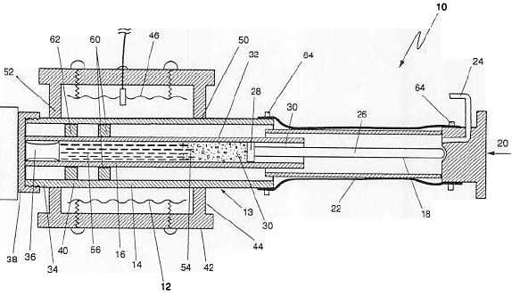


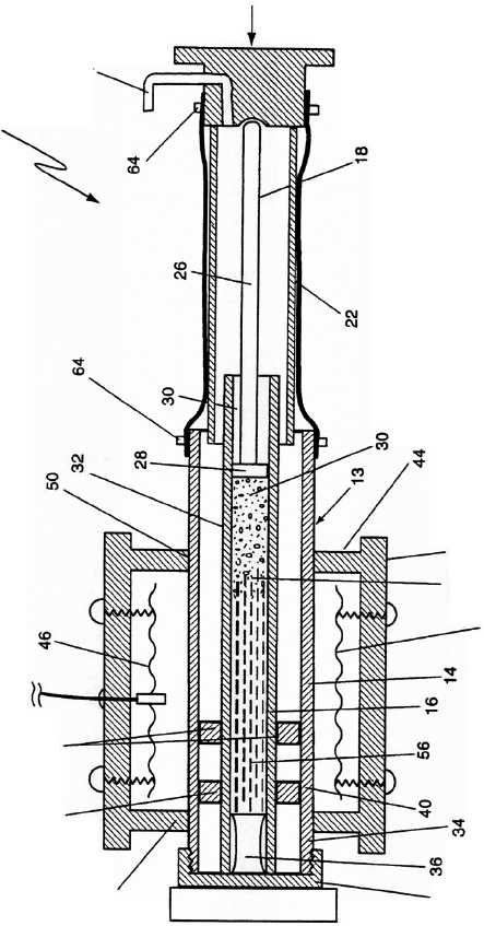


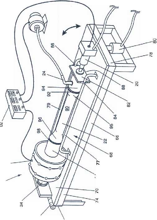


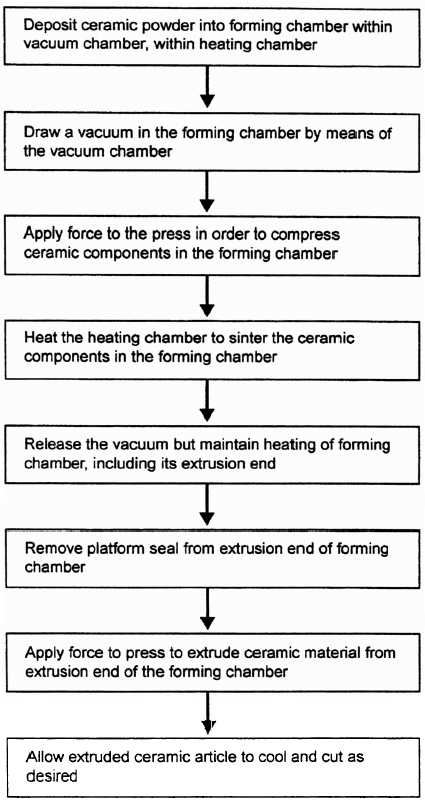


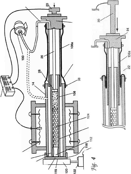


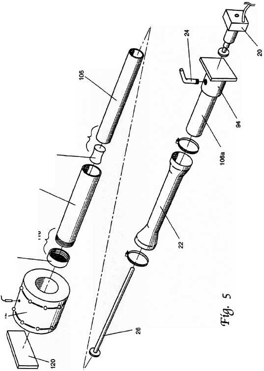


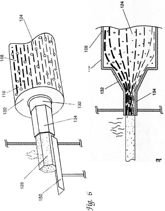


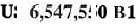


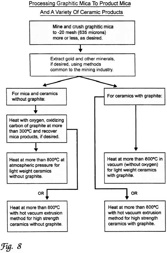
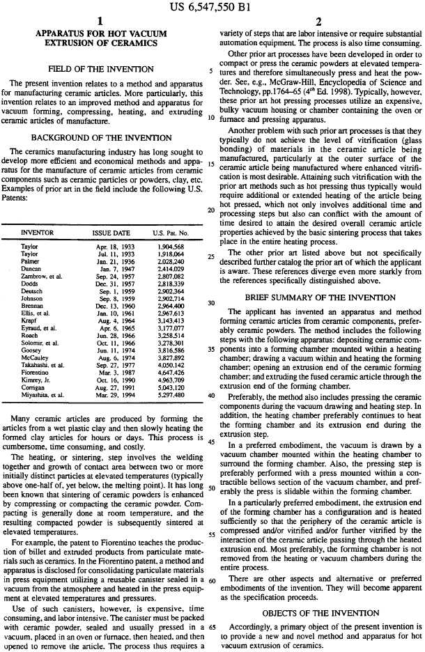
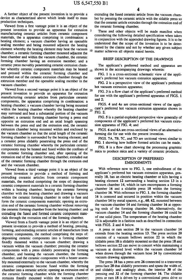
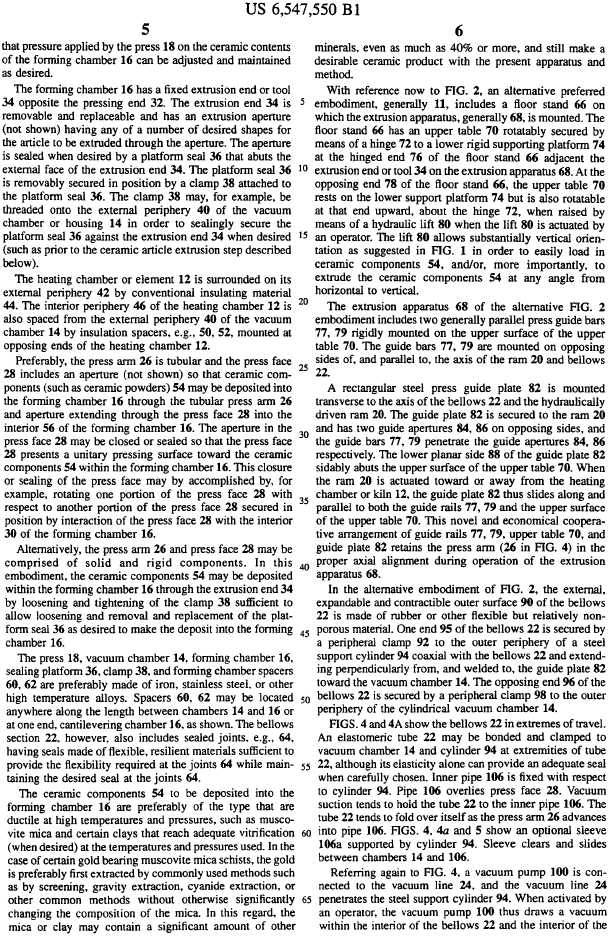


| | | | LOI | 21.82 12.64 2.91 7.04 1.38 1.82 | | 5.82 5.18 3.25 3.59 1.59 2.85 | | 4.03 | | 4.78 | | 2.6 | | 8.91 | | 2.24 | | 5.1 | | 3.82 | | 2.73 | | 3.03 | | 5.51 | | 6.36 3.48 | | 2.31 | | 5.75 | | 3.83 | | 3.29 2.33 1.82 | |
| | | | TiO2% | 0.04 0.01 0.72 0.79 0.82 0.8 | | 0.98 1.01 1.09 1.06 0.3 1.06 | | 1.07 | | 0.62 | | 0.66 | | 1.04 | | 0.99 | | 0.99 | | 0.91 | | 1.15 | | 0.83 | | 1.07 | | 1.17 0.2 | | 0.73 | | 0.53 | | 0.49 | | 0.11 0.89 0.36 | |
| | | | | | | | | | | | | | | | | | | | | | | | | | | | | | | | | | | | | 62.42 | |
| | | | SiO2% | 32.53 37.71 55.63 48.84 53.62 54.38 | | 48.44 46.1 48.58 48.22 64.19 50.04 | | 47.25 | | 48.53 | | 49.18 | | 42.35 | | 47.82 | | 49.08 | | 52.45 | | 52.44 | | 50.8 | | 49.22 | | 47.97 48.12 | | 51.7 | | 50.42 | | 49.33 | | 47.8 51.8 | |
| | | | S, total | 0.1 0.1 0.78 0.2 | | 0.03 0.11 0.15 0.03 0.01 0.02 | | 0.07 | | 0.05 | | 0.03 | | 0.4 | | 0.05 | | 0.13 | | 0.1 | | 0.09 | | 0.03 | | 0.09 | | 0.1 0.02 | | 0.17 | | 0.05 | | 0.02 | | 0.06 0.09 0 | |
| CERAMEXT ASSAY DATA BASE | | | P2O5% | 0.04 0.04 0.2 0.18 0.17 0.17 | | 0.11 0.14 0.18 0.13 0.17 0.11 | | 0.13 | | 0.06 | | 0.13 | | 0.12 | | 0.13 | | 0.15 | | 0.15 | | 0.12 | | 0.1 | | 0.12 | | 0.12 0.04 | | 0.05 | | 0.05 | | 0.05 | | 0.02 0.08 0.11 | |
| | | | | | | | | | | | | | | | | | | | | | | | | | | | | | | | | | | | | 5.74 | |
| | | | Na2O% | 0.07 -0.05 3.55 5.81 3.4 3.31 | | 3.72 4.15 3.82 3.6 6.19 4.15 | | 3.46 | | 3.06 | | 3.32 | | 2.66 | | 3.2 | | 3.06 | | 3.71 | | 3.32 | | 3.26 | | 3.72 | | 2.95 2.24 | | 3.24 | | 3.08 | | 3.09 | | 1.69 2.34 | |
| MODIFIED FROM: | Sept. 29, 2004 | | MnO% | 0.09 0.1 0.1 0.14 0.13 0.13 | | 0.17 0.16 0.23 0.15 0.1 0.2 | | 0.15 | | 0.15 | | 0.14 | | 0.2 | | 0.15 | | 0.17 | | 0.13 | | 0.15 | | 0.14 | | 0.19 | | 0.18 0.1 | | 0.13 | | 0.12 | | 0.12 | | 0.07 0.15 0.08 | |
| | | | MgO | 28.78 38.32 5.37 5.82 5.07 5.01 | | 8.07 8.05 8.82 8.44 2.32 9.01 | | 9.18 | | 9.91 | | 9.66 | | 8.4 | | 8.41 | | 7.58 | | 7.39 | | 8.14 | | 10.39 | | 8.48 | | 8.4 11.63 | | 10.4 | | 8.73 | | 9.97 | | 9.11 8.23 3.48 | |
| | | | K2O% | -0.1 -0.1 0.67 0.79 0.87 0.85 | | 0.1 0.41 0.37 0.34 0.76 0.19 | | 0.27 | | 0.51 | | 0.09 | | 0.18 | | 0.1 | | 0.13 | | 0.82 | | 0.22 | | 0.17 | | 0.17 | | 0.35 0.36 | | 0.1 | | 0.23 | | 0.13 | | 0.51 0.25 1.47 | |
| | | | Fe2O3% | 6.6 7.63 7.3 9.03 8.29 8.28 | | 10.08 10.46 11.72 11.02 5.28 10.58 | | 9.86 | | 9.46 | | 8.76 | | 10.63 | | 10.42 | | 10.06 | | 8.46 | | 10.07 | | 8.91 | | 9.65 | | 9.95 5.17 | | 7.96 | | 6.71 | | 6.53 | | 4.13 9.84 5.55 | |
| | | | Cr2O3% | 0.27 0.3 0.02 0.01 0.01 0.01 | | 0.06 0.04 0.03 0.03 0.01 0.03 | | 0.05 | | 0.07 | | 0.06 | | 0.04 | | 0.04 | | 0.03 | | 0.02 | | 0.02 | | 0.07 | | 0.03 | | 0.03 0.1 | | 0.05 | | 0.09 | | 0.12 | | 0.1 0.05 0 | |
| | | | C, Inorg | 0.21 0.06 1.06 0.01 | | 0 0.47 0.08 0.04 0.02 0.07 | | 0.22 | | 0.49 | | 0.01 | | 1.48 | | 0.04 | | 0.75 | | 0.23 | | | | | | | | | | | | | | | | | |
| | IDAHO-MARYLAND MINING CORP. | | C, Organic | -0.01 0.01 0.13 0.02 | | 0.2 0.15 0.06 0.08 0.04 0.07 | | 0.04 | | -0.01 | | 0.01 | | 0.07 | | -0.01 | | 0.08 | | 0.11 | | 0.03 | | 0.05 | | 0.12 | | 0.13 0.02 | | 0.04 | | 0.01 | | 0.03 | | 0.02 0.02 0.04 | |
| | | | C, Total | 0.2 0.07 1.19 0.03 | | 0.2 0.62 0.14 0.12 0.06 0.14 | | 0.26 | | 0.48 | | 0.02 | | 1.55 | | 0.03 | | 0.83 | | 0.34 | | 0.29 | | 0.2 | | 1 | | 1.23 0.08 | | 0.11 | | 0.01 | | 0.4 | | 0.05 0.03 0.19 | |
| | Project: | | CaO, % | 4.32 0.43 6.66 3.34 6.17 6.11 | | 6.14 8.72 6.3 7.08 1.71 6.73 | | 8.68 | | 8.24 | | 8.63 | | 9.67 | | 9.85 | | 9.61 | | 5.67 | | 8.99 | | 8.29 | | 7.87 | | 9.51 10.32 | | 9.09 | | 7.86 | | 10.85 | | 12.48 10.54 2.59 | |
| | | | Ba0 | 0.06 0.06 | | -0.001 -0.01 0.01 0.01 0.02 -0.01 | | -0.01 | | -0.01 | | -0.01 | | -0.01 | | -0.01 | | -0.01 | | 0.01 | | <0.01 | | <0.01 | | <0.01 | | 0.01 0.01 | | <0.01 | | <0.01 | | 0.01 | | <0.01 <0.01 0.03 | |
| | | | Al203 | 2.11 0.74 16.22 16.67 17.7 16.91 | | 15.02 16.06 15.4 16.14 16.43 14.76 | | 15.52 | | 14.68 | | 15.86 | | 15.08 | | 15.94 | | 14.19 | | 15.69 | | 14.64 | | 16.33 | | 14.89 | | 15.18 19.17 | | 15.89 | | 19.01 | | 17.62 | | 21.8 15.79 15.99 | |
| CERAMICS RESOURCE GEOCHEMISTRY DATABASE | | | Date | 04/20/2004 04/20/2004 04/20/2004 04/20/2004 06/03/2004 06/03/2004 | | 07/29/2004 07/29/2004 07/29/2004 07/29/2004 07/29/2004 07/29/2004 | | 07/29/2004 | | 07/29/2004 | | 07/29/2004 | | 07/29/2004 | | 07/29/2004 | | 07/29/2004 | | 07/29/2004 | | 08/26/2004 | | 08/26/2004 | | 08/26/2004 | | 08/26/2004 08/26/2004 | | 08/26/2004 | | 08/26/2004 | | 08/26/2004 | | 08/26/2004 08/26/2004 08/31/2004 | |
| | | | Lab | KCA-Florin KCA-Florin KCA-Florin KCA-Florin KCA-Florin KCA-Florin | | KCA-Florin KCA-Florin KCA-Florin KCA-Florin KCA-Florin KCA-Florin I-M | | KCA-Florin | | KCA-Florin | | KCA-Florin | | KCA-Florin | | KCA-Florin | | KCA-Florin | | KCA-Florin | | KCA-Florin | | KCA-Florin | | KCA-Florin | | KCA-Florin KCA-Florin | | KCA-Florin | | KCA-Florin | | KCA-Florin | | KCA-Florin KCA-Florin KCA-Florin | |
| | | | Assay Type | Whole Rock Whole Rock Whole Rock Whole Rock Whole Rock Whole Rock | | Whole Rock Whole Rock Whole Rock Whole Rock Whole Rock Whole Rock Extrusion | | Whole Rock Extrusion | | Whole Rock Extrusion | | Whole Rock Extrusion | | Whole Rock Extrusion | | Whole Rock Extrusion | | Whole Rock Extrusion | | Whole Rock Extrusion | | Whole Rock Extrusion | | Whole Rock Extrusion | | Whole Rock Extrusion | | Whole Rock Whole Rock Extrusion | | Whole Rock Extrusion | | Whole Rock Extrusion | | Whole Rock Extrusion | | Whole Rock Whole Rock Whole Rock Extrusion | |
| | | | Sample Type | Surface Surface Surface Surface Surface Surface | | Surface Surface Surface Surface Surface Surface IDH032, 125-135 ft. | | IDH032, 135-145 ft. IDH032, 671-681 ft. | | IDH032, 681-691ft. IDH033, 98-108 ft. | | IDH033, 108-118 ft. IDH033, 688-698 ft. | | IDH033, 698-708 ft. IDH034, 108-118 ft. | | IDH034, 118-128 ft. IDH034, 544-554 ft. | | IDH034, 554-564 ft. IDH034, 686-696 ft. | | IDH034, 696-706 ft. IDH035, 122-132 ft. | | IDH035, 132-142 ft. IDH035, 499-509 ft. | | IDH035, 509-519 ft. IDH036, 57-67 ft. | | IDH036, 67-77 ft. IDH036, 355-365 ft. | | IDH036, 365-375 ft. IDH037, 69-79 ft. IDH037, 79-89 ft. | | IDH037, 286-297 ft. IDH037, 297-307 ft. | | IDH038, 28-38 ft. IDH038, 69-79 ft. | | IDH038, 162-172 ft. IDH038, 188-198 ft. | | IDH038, 200-203 ft. Surface IDH034, 643--648 ft. Composite | |
| | | By B. Pease | Rock Type | Serpentine, alt Serpentine Andesite Breccia Diabase Andesite Breccia Andesite Breccia | | Andesite Intrusive Andesite Flow Andesite Flow Andesite Flow Dacite Intrusive Andesite Flow Andesite Flow | | Andesite Flow Andesite Intrusive | | Andesite Intrusive Andesite Flow | | Andesite Intrusive Andesite Intrusive | | Andesite Intrusive Andesite Flow | | Andesite Flow Andesite Flow Breccia | | Andesite Flow Breccia Andesite Flow Breccia | | Andesite Flow Breccia Diabase | | Diabase Diabase | | Diabase+Gabbro Andesite Tuff | | Andesite Tuff Andesite Flow | | Andesite Flow Gabbro Gabbro | | Diabase+Gabbro Diabase+Gabbro | | Diabase+Gabbro Diabase+Gabbro | | Diabase+Gabbro Diabase+Gabbro | | Gabbro Diabase Dacite Composite | All rocks are metamorphosed |
| | | | Sample No. | CX-1027 CX-1028 CX-1029 CX-1030 CX-1034.1 CX-1034.2 | | CX-1036 CX-1037 CX-1038 CX-1039 CX-1040 CX-1041 CX1042 | | CX-1043 CX1044 | | CX-1045 CX1046 | | CX-1047 CX1048 | | CX-1049 CX1050 | | CX-1051 CX1052 | | CX-1053 CX1054 | | CX-1055 CX1056 | | CX1057 CX1058 | | CX1059 CX1060 | | CX1061 CX1062 | | CX1063 CX1064 CX1065 | | CX1066 CX1067 | | CX1068 CX1069 | | CX1070 CX1071 | | CX1072 CX1073 CX1074 CX1075 | |
| | | | | | | | | | | | | | | | | | | | | | | | | | | | | | | | | | | | | | Note: |


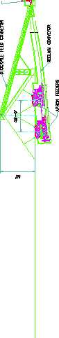
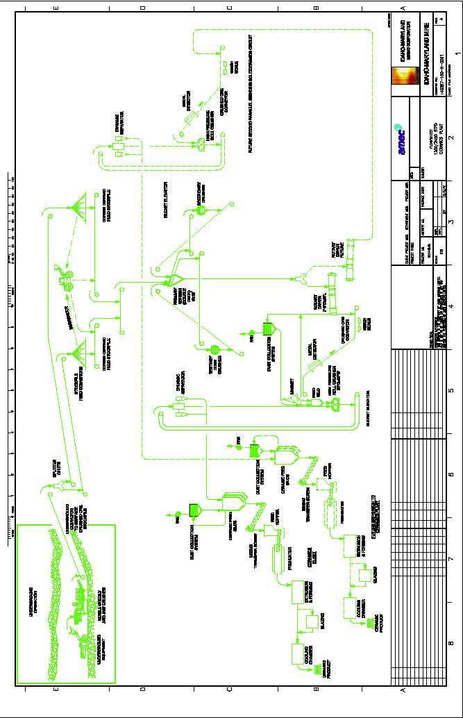
| Equipment List | | | | | |
|
|
| |
| |
| | | | | Motor Size | |
| Classification | Equipment Title | Size/ Capacity | | (hp) | |
|
|
| |
| |
| Process Plant (1,200 ton/d) | | | | |
| Conveyor | Stockpile Feed Conveyor #1 | 36" x 165 ft long | | 30 | |
| Conveyor | Stockpile Feed Conveyor #2 | 36" x 165 ft long | | 30 | |
| Feeder | Apron Feeder #1 | 18 ft long | | 30 | |
| Feeder | Apron Feeder #2 | 18 ft long | | 30 | |
| Feeder | Apron Feeder #3 | 18 ft long | | 30 | |
| Feeder | Apron Feeder #4 | 18 ft long | | 30 | |
| Conveyor | Coarse Ceramic Feed Stockpile Conveyor #1 | 36" wide x 250 ft long | | 15 | |
| Conveyor | Coarse Ceramic Feed Stockpile Conveyor #2 | 36" wide x 280 ft long | | 15 | |
| Conveyor | Coarse Ceramic Feed Stockpile Conveyor #3 | 36" wide x 110 ft long | | 10 | |
| Crane | Overhead Crane | 25 ton | | 50 | |
| Screen | Primary Screen | Double deck 6 x 16 L | | 30 | |
| Crusher | Secondary Crusher | HP 200 Standard Cone | | 150 | |
| Crusher | Tertiary Crusher | HP 200 Short Head Cone | | 150 | |
| Conveyor | Secondary Recycle Conveyor #1 | 36" wide x 13 ft long | | 10 | |
| Conveyor | Secondary Recycle Conveyor #2 | 36" wide x 77 ft long | | 10 | |
| Conveyor | Tertiary Recycle Conveyor #1 | 36" wide x 18 ft long | | 10 | |
| Conveyor | Tertiary Recycle Conveyor #2 | 36" wide x 93 ft long | | 10 | |
| Conveyor | Rotary Dryer Feed Screw Conveyor #1 | 42 ft long | | 10 | |
| Dryer | Rotary Dryer #1 | 6 ft diameter x 48 ft long | | 100 | |
| Dust Collector | Rotary Dryer Dust Collector #1 | - | | - | |
| Fan | Rotary Dryer Dust Collector Fan #1 | - | | 50 | |
| Conveyor | Crushed Ore Conveyor #1- HAC | 36" wide x 30 ft long x 27 ft Lift | | 60 | |
| Weigh Scale | Crushed Ore Conveyor Belt Weigh Scale #1 | 36" wide, 200 ton/h | | - | |
| Belt Magnet | Crushed Ore Conveyor Belt Magnet #1 | - | | 10 | |
| Rectifier | Belt Magnet Rectifier | 10 kW | | incl | |
| Metal Detector | Tramp Steel Metal Detector #1 | 36" wide | | - | |
| Silo | HPGR Feed Silo #1 | 120 ton | | - | |
| Grinding Roll | High Pressure Roll Crusher #1 | Studded rolls- 55" diameter x 32" wide | | - | |
| | HPRC #1 Motor 1 | - | | 450 | |
| | HPRC #1 Motor 2 | - | | 450 | |
| | Deagglomerator on HPGR #1- 1 | - | | 60 | |
| | Deagglomerator on HPGR #1- 2 | - | | 60 | |
| Elevator | Bucket Elevator #1 | 63 ft high | | 50 | |
| Dust Collector | HPRC Dust Collector #1 | - | | - | |
| Fan | HPRC Dust Collector Fan #1 | - | | 50 | |
| Separator | Ceramic Dynamic Separator #1 | SEPOL separator with wear linings | | 150 | |
| Transfer System | Pneumatic Transfer System | 1200 ton/d | | 100 | |
| Conveyor | HPRC Recycle Belt Conveyor #1 | 35 ft long | | 10 | |
| Compressor | Plant Air Compressor | 500 cfm 125 psi | | 200 | |
| Compressor | Instrument Air Compressor | 250 cfm 125 psi | | 150 | |
| Dryer | Compressed Air Dryer | 250 cfm | | | |
| Receiver | Process Air Receiver | 2,000 gal 125 psi | | - | |
| Receiver | Instrument Air Receiver | 400 gal 125 psi | | - | |
| | | Horsepower | | 2600 | |
|
|
| |
| |
| Ceramics Extruder Plant (1,200 ton/d) | | | | |
| Silo | Ceramic Feed Storage Silo #1 | 15 ft diameter x 39 ft high (245 ton) | | - | |
| Silo | Ceramic Feed Storage Silo #2 | 15 ft diameter x 39 ft high (245 ton) | | - | |
| Silo | Ceramic Feed Storage Silo #3 | 15 ft diameter x 39 ft high (245 ton) | | - | |
| Silo | Ceramic Feed Storage Silo #4 | 15 ft diameter x 39 ft high (245 ton) | | - | |
|
|
| |
| |
| | | | | Motor Size | |
| Classification | Equipment Title | Size/ Capacity | | (hp) | |
|
|
| |
| |
| Silo | Ceramic Feed Storage Silo #5 | 15 ft diameter x 39 ft high (245 ton) | | - | |
| Dust Collector | Storage Silos Dust Collector #1 | - | | - | |
| Fan | Storage Silos Dust Collector Fan #1 | - | | 50 | |
| Bin | Ceramics Bin #1 | - | | - | |
| Bin | Additives Bin #1 | - | | - | |
| Conveyor | Mixing Transfer Screw Conveyor | - | | 30 | |
| Hopper | Preheater Feed Hopper | - | | - | |
| Preheater | Ceramics Preheaters | 22 MW gas heating load includes | | | |
| | | drying and preheating | | | |
| Fan | Preheater Fans | - | | incl | |
| Hopper | Extruder Feed Hoppers | - | | - | |
| Extruder | Ceramics Extrusion and Forming Systems | 9 MW electric heating load | | 11,775 | |
| Glazing | Glazing Systems | - | | incl | |
| Furnace | Cooling Furnaces | - | | incl | |
| Fan | Cooling Furnace Fans | - | | incl | |
| Racks | Cooling Racks | - | | incl | |
| Pump | Extruder Vacuum Pumps | - | | incl | |
| Hydraulic Power Pack | Extruder Drive Hydraulic Power Packs | - | | incl | |
| | | Horsepower | | 11.975 | |
|
|
| |
| |
| Future Parallel Grinding Roll/ Ceramics Circuit (expansion to 2,400 ton/d) | | | |
| Dryer | Rotary Dryer #2 | 6 ft diameter x 48 ft long | | 100 | |
| Dust Collector | Rotary Dryer Dust Collector #2 | - | | - | |
| Fan | Rotary Dryer Dust Collector Fan #2 | - | | 50 | |
| Conveyor | Crushed Ore Conveyor #2- HAC | 36" wide x 30 ft long x 27 ft lift | | 60 | |
| Weigh Scale | Crushed Ore Conveyor Belt Weigh Scale #2 | 36" wide, 200 ton/h | | - | |
| Belt Magnet | Crushed Ore Conveyor Belt Magnet #2 | - | | 10 | |
| Metal Detector | Tramp Steel Metal Detector #2 | 36" wide | | - | |
| Silo | HPGR Feed Silo #2 | 120 ton | | - | |
| Grinding Roll | High Pressure Roll Crusher #2 | Studded rolls- 55" diameter x 32" wide | | - | |
| | HPGR #2 Motor 1 | - | | 450 | |
| | HPGC #2 Motor 2 | - | | 450 | |
| | Deagglomerator on HPRC #2-1 | - | | 60 | |
| | Deagglomerator on HPRC #2-2 | - | | 60 | |
| Elevator | Bucket Elevator #2 | 63 ft high | | 50 | |
| Dust Collector | HPRC Dust Collector #2 | - | | - | |
| Fan | HPRC Dust Collector Fan #2 | - | | 50 | |
| Separator | Ceramic Dynamic Separator #2 | SEPOL separator with wear linings | | 150 | |
| Transfer System | Pneumatic Transfer System | 1200 ton/d | | 100 | |
| Conveyor | HPRC Recycle Belt Conveyor #2 | 35 ft long | | 10 | |
| | | Horsepower | | 1,600 | |
|
|
| |
| |
| Future Ceramics Plant (expansion to 2,400 ton/d) | | | | |
| Silo | Ceramic Feed Storage Silo #6 | 15 ft diameter x 39 ft high (245 ton) | | - | |
| Silo | Ceramic Feed Storage Silo #7 | 15 ft diameter x 39 ft high (245 ton) | | - | |
| Silo | Ceramic Feed Storage Silo #8 | 15 ft diameter x 39 ft high (245 ton) | | - | |
| Silo | Ceramic Feed Storage Silo #8 | 15 ft diameter x 39 ft high (245 ton) | | - | |
| Silo | Ceramic Feed Storage Silo #10 | 15 ft diameter x 39 ft high (245 ton) | | - | |
| Dust Collector | Storage Silos Dust Collector #2 | - | | - | |
| Fan | Storage Silos Dust Collector Fan #2 | - | | 50 | |
| Bin | Ceramics Bins | - | | - | |
| Bin | Additives Bins | - | | - | |
| Conveyor | Mixing Transfer Screw Conveyors | - | | 30 | |
|
|
| |
| |
| | | | Motor Size | |
| Classification | Equipment Title | Size/ Capacity | (hp) | |
|
|
|
| |
| Hopper | Preheater Feed Hoppers | - | - | |
| Preheater | Ceramics Preheaters | 22 MW gas heating load includes | - | |
| | | drying and preheating | | |
| Fan | Preheater Fan #2 | - | incl | |
| Hopper | Extruder Feed Hopper #2 | - | - | |
| Extruder | Ceramic Extrusion and Forming System | 9 MW electric heating load | 11,775 | |
| Glazing | Glazing System | - | incl | |
| Furnace | Cooling Furnaces | - | incl | |
| Fan | Cooling Furnace Fans | - | incl | |
| Racks | Cooling Racks | - | incl | |
| Pump | Extruder Vacuum Pumps | - | incl | |
| Hydraulic Power Pack | Extruder Drive Hydraulic Power Packs | - | Incl | |
| | | Horsepower | 11,975 | |
| | | Total Horsepower 1,200 ton/d plant | 14,575 | |
| | | Total Horsepower 2,400 ton/d plant | 28,150 | |
| | |
|
| |