Exhibit 99.1
Executive Summary for
Root Cause Analysis of Kingston Dredge Cell Failure
The failure occurred around 1:00 a.m. EST, on Monday, December 22, 2008, when the north and central portions of Cell 2 at the Kingston Fossil Plant ash disposal site suddenly failed. An estimated 5.4 million cubic yards of material, consisting primarily of hydraulic-filled ash and intermediate stage containment dikes, were released in a progressive sequence of flow slides over a period of approximately one hour. Ultimately, the flow slide would extend northward approximately 3,200 feet beyond the limits of the original ash pond over the Swan Pond Creek flood plain, a back water slough of the Emory River and into the former Emory River Channel of Watts Bar Reservoir. Prior to reaching the Emory River channel, the slide mass inundated several TVA-owned sloughs, spread onto eight acres of private property and damaged several structures.
Background Information
The land surrounding the power plant is undeveloped and only sparsely populated. The disturbance created by the slide created a flood water response wave that ran upstream and downstream of the surrounding waterways. The combined mass of flowing ash and water pushed one single-family home entirely off its foundation, and ultimately rendered three structures uninhabitable. It is estimated that as many as 42 residential properties may have been affected. A reported 22 residences were evacuated, but no injuries or individuals in need of hospitalization were identified.
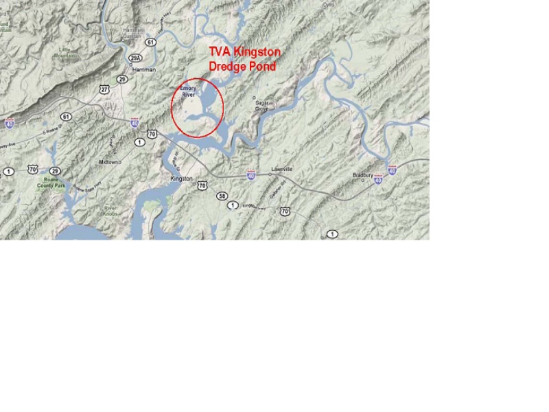
The Kingston Fossil Plant is a 1,700-MW coal-burning power plant located in Roane County, Tennessee on a peninsula formed by the confluence of the Emory River (to the north) and the Clinch River (to the south and east). Begun in 1951 as the Kingston Steam Plant, the facility was conceived and built to supply nearby Oak Ridge atomic energy installations with a steady supply of electricity. When it was commissioned in 1955, it was reportedly the largest coal-fired power plant in the world.
Figure ES_1: Site Location
Site History and Chronology of Dredge Cell Development
Water for the Tennessee Valley Authority (TVA) Kingston plant is drawn from the reservoir created by Watts Bar Dam which is located midway between Knoxville and Chattanooga, roughly 38 miles downstream from the mouth of the Clinch River. Construction of Watts Bar Dam began in 1939, it was completed in 1942, and it is one of nine TVA dams on the Tennessee River. The reservoir stretches approximately 72 miles along the Tennessee River, and it creates a slack-water reservoir with channels that extends more than 20 miles up the Clinch River and 12 miles up the tributary Emory River. The failed dredge cells are located two miles up the Emory River from its historic confluence with the Clinch River.
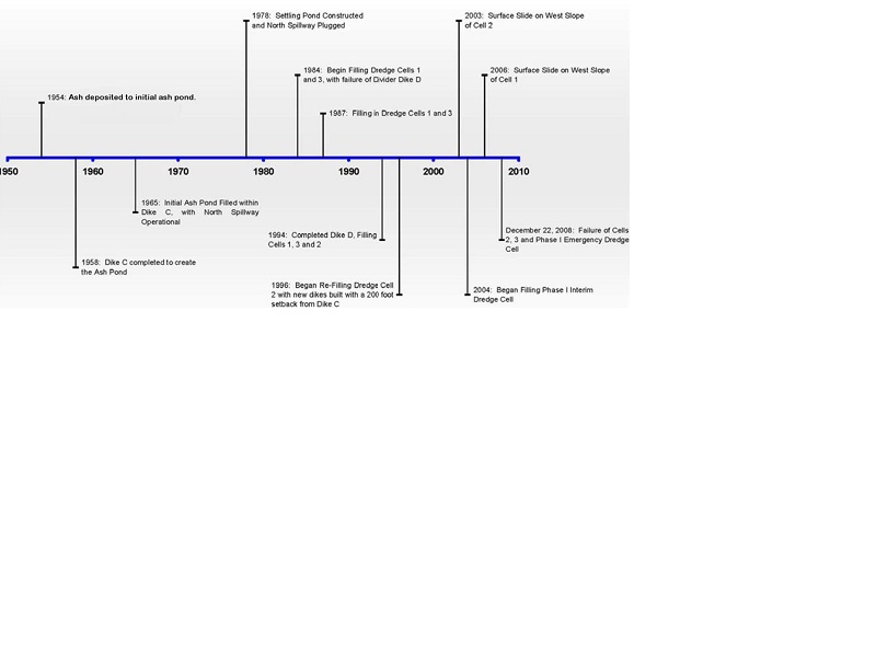
Figure ES_2: Dike construction, ash filling, and key event timeline
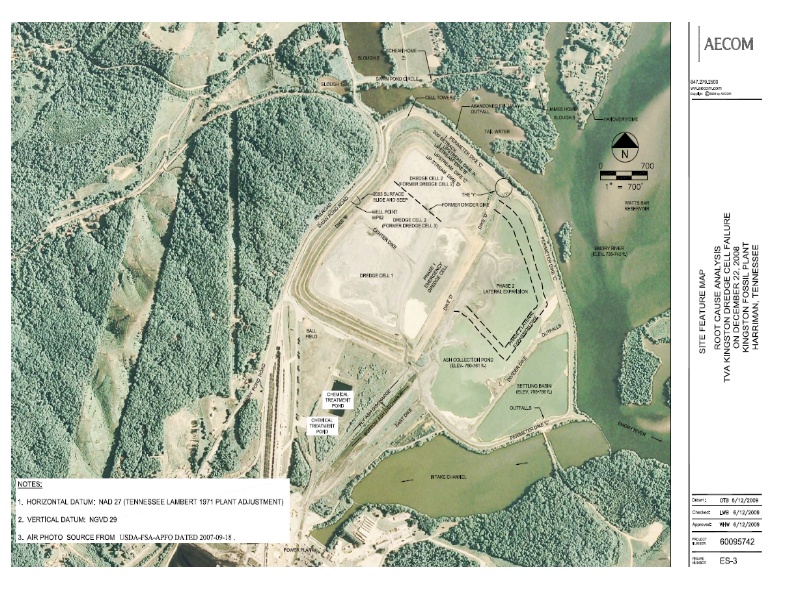
The initial 1954, 85-acre ash pond and more expansive 275-acre final storage area, completed in 1958, are located immediately north of the Kingston Fossil Plant along the bank of the former Emory River at the confluence with Swan Pond Creek and its flood plain. The 275-acre storage area consists of the main pond where ash is deposited and a stilling pond where process water can settle out fine-grained material and decant water back to the Reservoir. Once the initial ash ponds were full in the early 1980s, the TVA began to dredge ash from a collection pond and to construct elevated dredge cells with containment dikes where ash from the main pond is finally placed. Between 1954 and 1990, the loose wet ash placed in the dredge cells accumulated to a depth of 40 to 65 feet. Figure ES_3 shows an aerial photograph of the site with key features labeled.
The Portland Cement Association describes flyash as a finely divided residue that results from combustion of pulverized coal in electric power generating plants. During combustion in a conventional plant, mineral impurities within the coal (e.g., clay, feldspar, quartz, and shale) fuse in suspension and, as they cool, solidify into flyash which is primarily silicate glass. The flyash is separated and collected from the combustion exhaust gas and hydraulically pumped through pipes to the ash ponds. When viewed through a scanning electron microscope, the majority of flyash particles are revealed to be solid spheres and hollow cenospheres.
Engineered red earthen perimeter dikes named “East Dike” and “Dike C” were constructed between 1951 and 1958 on alluvial flood plain deposits of clay, silt, and sand. These dikes create the initial impoundment which has come to be known as the ash pond. The clay, silt, and sand alluvium under the ash pond extends between approximately 20 and 40 feet to the Conasauga Shale. The Conasauga Shale is a Cambrian-aged formation that consists of folded and fractured shales with minor layers of limestone and dolomite. The Conasauga extends into Alabama, Georgia and Virginia. The shale is not locally karstic and artesian conditions have not been observed for the formation.
Prior to 1958 before Dike C was completed to fully contain the ash pond, the ash stream was discharged directly to the Watts Bar Reservoir. The slurry of ash and water naturally flowed out across the floor of the storage area. Although well mixed and turbulent at the point of discharge next to the power plant, the ash stream eventually became stagnant in the containment area and the suspended solids began to precipitate out in a deltaic manner. What resulted was a thin (less than about six-inches thick) laminated structure of interbedded flyash, eroded dike soils and re-deposited river sediments within the footprint of the future as storage cell. The spillway for this containment pond operated from 1958 to 1977 and was located at the north end of Dike C 5,200 feet from the point discharge next to the plant. This small grained material is referred to as “slimes” as this term applies to the fine-size sediments having a slippery, viscous feel. The thin laminated layer at the base of the dredge cell will be described as a soft sensitive slime for the purposes of this study. AECOM did not find slimes under Dredge Cell 1 or the Phase 1 Emergency Dredge Cell during our exploration likely due to over-excavation of ash in 1984 and being closer to the point of discharge.
| Log | Thickness (ft) | Profile Depth (ft) | Description |
| | 0-90 | 90 | Loose Ash Fill |
| | <0.5 | 90 | Slimes |
| | 0 to 15 | 90 to 105 | Clay and Silt Alluvium |
| | 10 to 20 | 110 to 125 | Silty Sand and Silt Alluvium |
| | Greater than 50 feet | 125+ | Conasauga Shale |
TABLE ES_T1: Typical Subsurface Profile at top of North Dredge Cell 2 |
The ash storage pond was originally shown on engineering drawings prepared by the TVA in 1951. Modifications and additions to increase the original storage capacity of the ash ponds were made throughout the decade of the 1970’s. By 1985, Dike C was being raised for the third and final time. A few isolated outbreaks of seepage had been observed over the years on the Dike C perimeter dikes, and stability analyses at the time indicated that any additional expansion next to the Dike C reservoir alignment would require a setback from the original storage pond limits to reduce seepage forces acting on the dikes.
In 1995, TVA designed and began construction of a vertical dredge cell expansion program that was permitted in 2000. A Solid Waste Permit was issued by the Tennessee Department of Environment and Conservation (TDEC) to raise Dredge Cells 1, 2, and 3 using upstream dike construction methods to form an approximately 120-acres sluiced ash storage structure. In this process, small perimeter dikes are constructed in stages, with the subsequent dikes bearing on the lower dikes and a portion of each perimeter dike placed over previously sluiced ash, as a set-back to flatten slopes. The compacted dikes include an internal seepage control system and are usually constructed one stage in advance of filling. The dikes step inward as the overall height of the cell increases on an average slope of four horizontal to one vertical. Because the plan area of cells decreases with each inward step of the dikes, the available storage area the cell decrease as the height increases. Assuming the placement volume remains constant, the rate of vertical expansion of the cell increases over time. The raising program of the cells designed in 1995 was planned to be complete by 2014.
A shallow slide with a small release of sluiced ash occurred on the west side of Dredge Cell 2 in 2003 and small seepage outbreaks were observed in 2006, which were followed by remedial efforts to contain and collect seepage. Plans for a three phase lateral and vertical expansion program of the dredge cells were prepared between 2004 and 2006 to extend the design life of the ash storage facility beyond 2014. TDEC permitted construction and filling of the Phase 1 Emergency Dredge Cell was performed between 2004 and 2007, and Phase 2 lateral expansion cell was subsequently discharge to in 2007 and 2008. From October 16 to December 18, 2008, TVA reported that 100,000 cubic yard of ash material was placed within 31-acre Dredge Cell 2. For the plan area at the time, the placement vertical fill height rate is estimated to be approximately 6 feet/year.
Between November 20 and December 21, 2008 meteorological records indicate that no more than 8 inches of rain fell on the ash storage site. Early December rains swelled the reservoir by approximately 3 feet, but by December 21, it had been lowered to pre-rainfall level, well within normal operating limits of the reservoir. Approximately 1-inch of rain was reported for the day prior to failure, but inspections at noontime on December 21, 2008 did not observe adverse conditions, evidence of seepage, or shallow instability. It is unlikely that the rainfall had any significant affect on the stability of the structure. The only noted wetness was near water well (WP02), out of several dozen wells along the toe of the west slope of Cell 2. This wet area was noted on December 21, 2008 next to a 2006 seepage repair area. The inspection report from December 21, 2008 did not report evidence of shallow slides, piping, or slope instability at this area.
Failure Scenario
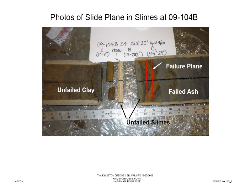
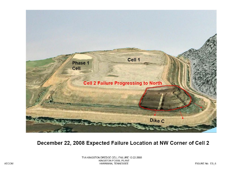
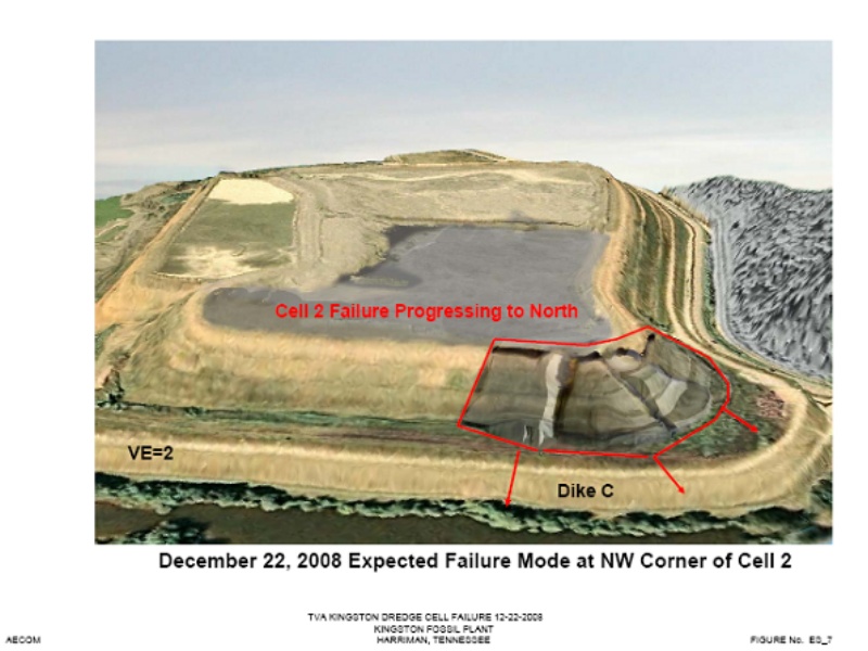
Based on the post-failure explorations, testing and analyses completed by AECOM, the initial failure most likely occurred in the northwest corner of Dredge Cell 2, and it was initially contained within the footprint of the structure defined by perimeter Dike C. Based on photographic evidence of slide planes in undisturbed samples, the slide plane extended as far down as the underlying slimes. Stability analyses indicate that the toe (i.e., the lower margin of the displaced material) of the initial failure mass was initially contained within the 200-foot buffer zone that separates the upstream dike expansion from perimeter Dike C. This initial failure was rapidly followed by a series of progressive failures that ultimately breached Dike C.
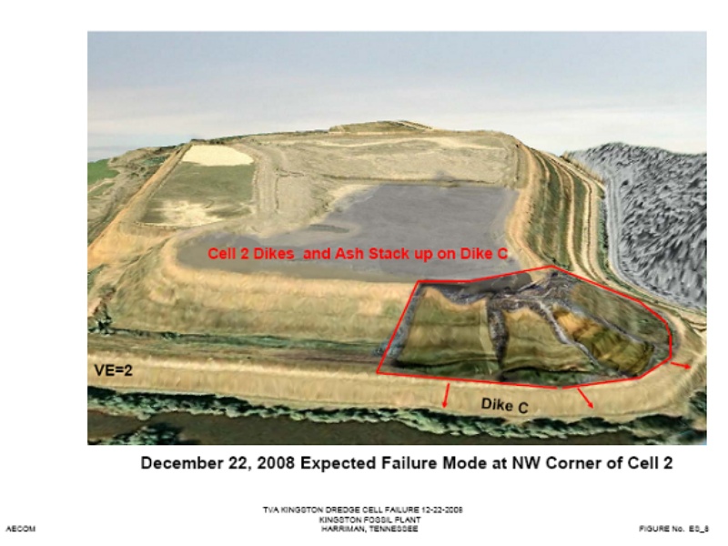
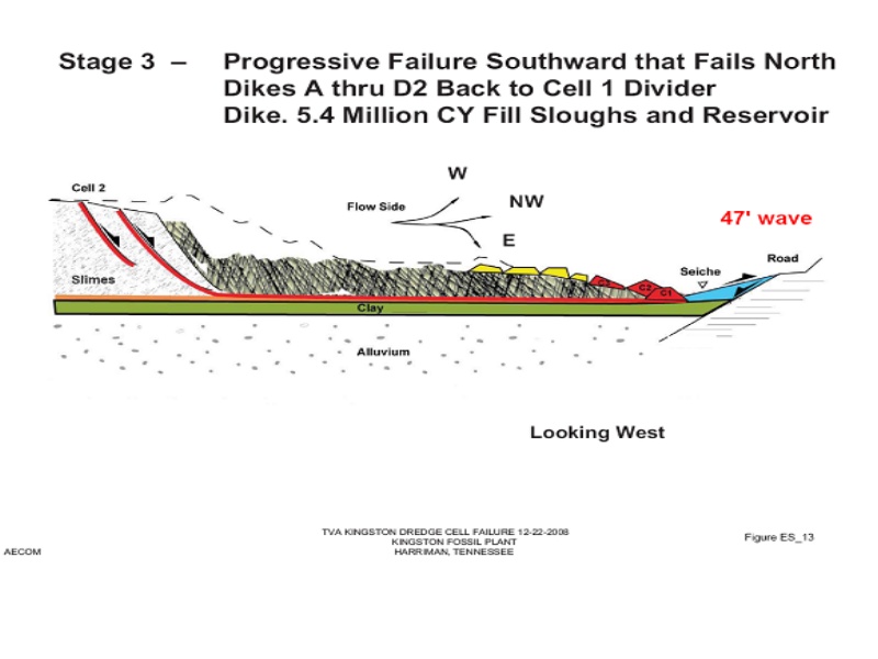
In a process termed static liquefaction, loose wet ash behind the breached northwest Dredge Cell 2 began to flow as if it were a viscous liquid. The upstream dikes were carried by ash and displaced laterally across the 200-foot setback area comprised of a 40-foot thick layer of old sluiced ash and along with liquefied ash, thrust up against perimeter Dike C, which slid north and west over the alluvial clay deposit at its base. Sloughs 1 and 2 north of the ash pond, were overrun by an outpouring of fluid and dike fragments that created an estimated 47-foot high flood wave or seiche that extended across the backwater slough or tail water of the relocated Swan Pond Creek and up the north hillside, into east Slough 3 which is a backwater channel off the reservoir, and then into the former Emory River channel. Fragments of Dike C and the water wave from the breach pushed the Schean home off its foundation and onto Swan Pond Circle. A telephone call, apparently from the Schean’s, was the first documented public notice of the failure.
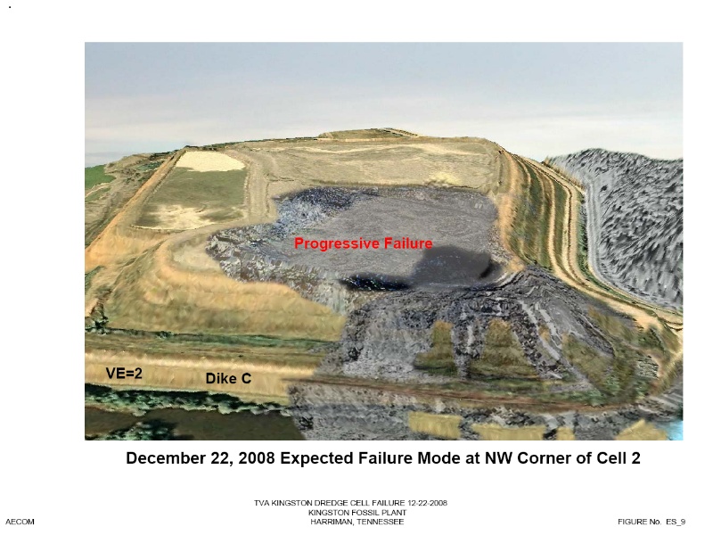
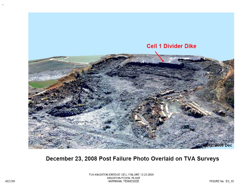
The scarp of the initial failure began to sequentially progress backwards in Cell 2 as the wet ash lost strength and liquefied. To the south, the sequence of failures was halted by the Cell 1 Divider Dike. With each wall failure, greater and greater volumes of ash were released, triggering still more progressive failures from north to south. At its peak, the slide mass had sufficient volume and energy to extend almost 3,200 feet beyond the limits of breached Dike C up Slough 2 and against the current in the Emory River channel, more than 1,600 feet to the Emory River channel, and nearly 1,000 feet up Slough 3, a side channel to the reservoir. Ash extended almost 500 feet into the reservoir and forced the flow of the Emory River eastward. As a consequence of this failure a portion of the Phase 1 Emergency Dredge Cell lost an upper portion of its contents, but did not experience a deep failure.
Although there has been historic slope and seepage instability along the west side of Cell 2, documented photographic and test boring evidence indicates that dredge cell dike slope instability was shallow and ash inundated rather than undermined Swan Pond Road and the railroad tracks. This is also supported by the fact that many of the AECOM borings conducted along Swan Pond Road showed evidence of only shallow dike and ash instability, while borings conducted 75 feet east Swan Pond Road displayed evidence of deep liquefaction of the ash. The fact that many of the west-facing dike remnants flowed toward the north, on top of ash, as partially intact relics also supports this conclusion that instability did not start along the west slope of the fill.
Based on written witness reports and TVA call logs, the slide event is estimated to have occurred over a span of approximately one hour, with the north side Cell 2 area failing in a sudden and dramatic manner. From AECOM’s review of the records and our observations, the failure was very sudden and dramatic, with each successive slide causing rapid movement of the failing mass, with only minimal delay between slides. Survey monuments, a cell phone tower, construction equipment, railroad line, piping, and vegetation were all displaced by the flow. A bulldozer was found almost 1,000 feet from its pre-slide location, and a scraper floated more than 1,200 feet north of the previous day’s location. Known cattails in the 200-foot setback next to Dike C north of Dredge Cell 2 moved 3,200 feet north up Slough 2, to an area northwest of the Schean home. Ground shaking, probably from the ash movements during failure was reported at the north end of Cell 1 in the vicinity of the access road which runs along the left bank of the Emory River. No earthquakes were recorded by local seismic monitoring stations at the time of the failure.
Probable Failure Modes
There were several factors acting together that lead to the failure and to the large magnitude of displacements of the failure mass:
| 1. | The dredge cell footprint area became progressively smaller with each dike raise. Therefore, more height was required to store the same annualized ash volume generation, and thus the elevation of sluiced ash was increasing more rapidly. The added height of ash behind the upstream dike construction added load to the wet ash and to the unusual slimes at the dredge cell foundation level. Active Cell 2 at the north side was being raised at rate of 6.1 feet/year. This rate is less than the filling rate of the Phase 1 Emergency Cell that was loaded at a rate of 14.6 feet/year from 2004 to the end of 2006. |
| 2. | The 3H:1V sloping upstream dikes with 15-foot wide benches were founded on 35 to 40 feet of wet ash and located 200 feet back from the original containment Dike C. Thus the upstream dikes did not benefit from the better foundation conditions under the original Dike C, where no slimes were found. |
| 3. | Creep failure of the loose slimes was occurring under the loose wet ash, reducing the available strength of the slimes. The slimes are unusual in that they are soft, wet, had low shear strength and were susceptible to creep. Figure ES_4 following this Executive Summary shows a photograph of the slide plane in the slimes under Cell 2 in between unfailed clay and failed ash. Based on AECOM’s explorations, Cell 2 is underlain by slimes, but slimes were not found in AECOM borings under Cell 1 or under the Phase 1 Emergency Dredge Cell. Cell 1 was closer to the discharge of sluiced ash, thus finer materials such as those observed in the slimes would have been transported further north. The Phase 1 Emergency Dredge Cell was over-dredged in 1984 and the associated failure, likely removed the slimes in this area. This is a likely reason why Cell 1 and the Phase 1 Emergency Dredge Cell did not fail earlier. |
| 4. | The initial loose, sluiced ash was placed underwater with a resulting high void ratio with no evidence of consolidation or densification under the weight of fill placed over older ash. As a result, the wet ash remained very loose and susceptible to collapse if subject to rapid loading or rapid displacement. The ash was highly contractive, leading to low undrained strengths with a very sensitive structure (low strain at peak strength). Active ash loading in Cell 2, creep in the weak slimes and limited drainage caused undrained behavior in the loose ash at low strain levels. Ash behavior changed from drained to undrained behavior which leads to very low shear strength in the ash with only slight deformation. This is termed a static liquefaction failure and led to the very large movements of the failure mass. |
Summary
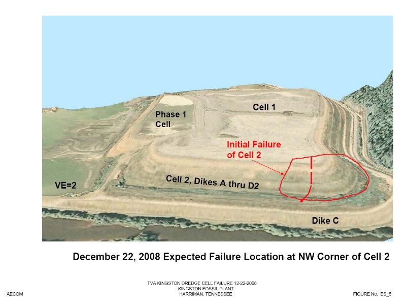
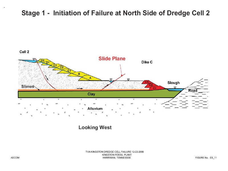
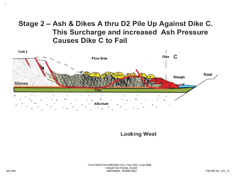
The north end of Dredge Cell 2 was on the verge of failure due to the high stresses and creep in the loose wet layer of weak slimes. The deformation of the slimes in turn caused the overlying collapsible wet ash to liquefy. Figures ES_5 through ES_10 following this Executive Summary show AECOM’s orthographic interpretation of the initial failure location and apparent failure sequence at the north end of Cell 2. Failure of the Kingston dredge cells was sudden and complex in nature due its geographic setting and being built within the Watts Bar Reservoir after the lake was formed. It took a forensic type study to determine the propensity of the ash to liquefy at low strain levels when the material cannot drain and thus becomes undrained, and to locate the slide plane in the unusual, creep susceptible, low undrained shear strength slime layer that underlies Cell 2. In AECOM’s opinion, subsurface conditions at the dredge cells were unusual and rarely found. The consequence of failure in the slimes led to the collapse of the dredge cell and loss of the saturated contents of the ash landfill due to the breach of perimeter Dike C. Figures ES_11, ES_12, and ES_13 show AECOM’s interpretation of progressive failure at the northwest end of Cell 2 and containment Dike C.
Figures ES_3 through ES_13
[