Exhibit 96.1
 |  |
 | Las Chispas Operation S-K 1300 Technical Report Summary Sonora, Mexico Effective Date: December 31, 2024 Prepared for: Coeur Mining, Inc. 200 South Wacker Drive, Suite 2100 Chicago, IL 60606 USA Prepared by: Ausenco Engineering Canada ULC 1050 West Pender Street, Suite 1200 Vancouver, British Columbia V6E 3S7 Canada  |
 |  |
Date and Signature Page
This technical report, entitled “S-K 1300 Technical Report Summary on the Las Chispas Operation, Sonora, Mexico is current as of December 31, 2024, and filed on February 19th, 2025, and has been prepared by:
| QP Name or Company | Responsible for the Following Sections | Signature | Date | ||
| Ausenco Engineering Canada ULC | 1.9,1.13,1.16,2,9.3,10,14,17,22.5,22.8,22.11,22.14.1.2, 22.14.2.5, 23.6, 24 | “Signed” | |||
| Christopher Pascoe, RM SME | 1.1,1.14,1.15,1.17,1.18,1.19,2,15,16,18,19,20,21,22.1, 22.9, 22.10, 22.12, 22.13, 22.14.1.5, 22.14.2.6, 22.14.2.7, 23.1, 24, 25 | “Signed” | |||
| Joseph Wallick, P.Eng | 1.11,1.12,2,12,13,22.6,22.7,22.14.1.4, 22.14.2.4, 22.14.2.5,23.5, 24 | “Signed” | |||
| P&E Mining Consultants, Inc. | 1.2,1.3,1.4,1.5,1.6,1.7,1.8 1.10, 3, 4, 5, 6, 7, 8, 9.1, 9.2, 9.4, 11, 22.2,22.3,22.4,22.14.1.1, 22.14.1.3, 22.14.1.4, 22.14.2.1, 22.14.2.2, 22.14.2.3, 23.2, 23.3, 23.4, 24 | “Signed” |
| |
| 1 | EXECUTIVE SUMMARY | 1 | ||
| 1.2 | Introduction | 1 | ||
| 1.3 | Project Setting | 1 | ||
| 1.4 | Property Description and Location | 2 | ||
| 1.5 | History | 3 | ||
| 1.6 | Geology and Mineralization | 3 | ||
| 1.7 | Exploration and Sampling | 4 | ||
| 1.8 | Drilling and Sampling | 5 | ||
| 1.9 | Data Verification | 7 | ||
| 1.10 | Metallurgical Testwork | 8 | ||
| 1.11 | Mineral Resource Estimate | 8 | ||
| 1.12 | Mineral Reserve Estimate | 11 | ||
1.11.1 | Estimation Methodology | 11 | ||
1.11.2 | Mineral Reserve Statement | 12 | ||
1.11.3 | Factors that May Affect the Mineral Reserve Estimate | 13 | ||
| 1.13 | Mining Methods | 13 | ||
| 1.14 | Recovery Methods | 14 | ||
| 1.15 | Project Infrastructure | 16 | ||
1.14.1 | Introduction | 16 | ||
1.14.2 | Waste Rock Storage Facility | 19 | ||
1.14.3 | Ore Stockpiles | 19 | ||
1.14.4 | Filtered Tailings Storage Facility | 19 | ||
1.14.5 | Power and Fuel | 19 | ||
1.14.6 | Camp | 19 | ||
1.14.7 | Water Management | 20 | ||
| 1.16 | Market Studies and Contracts | 20 | ||
| 1.17 | Environmental Studies, Permitting and Social or Community Impact | 21 | ||
1.16.1 | Environmental Considerations | 21 | ||
1.16.2 | Permitting Considerations | 21 | ||
1.16.3 | Environmental Management Plans | 22 | ||
1.16.4 | Waste Considerations | 22 | ||
1.16.5 | Social and Community Considerations | 22 | ||
1.16.6 | Closure Considerations | 23 | ||
| 1.18 | Sustaining Capital and Operating Costs | 23 | ||
| |
| 1.17.1 | Sustaining Capital Cost Estimates | 23 | ||
| 1.17.2 | Reclamation and Closure Cost Estimates | 23 | ||
| 1.17.3 | Operating Cost Estimate | 24 | ||
| 1.19 | Economic Analysis | 24 | ||
| 1.20 | Recommendations | 25 | ||
| 2 | INTRODUCTION | 27 | ||
| 2.1 | Introduction | 27 | ||
| 2.2 | Report Purpose | 27 | ||
| 2.3 | Terms of Reference | 27 | ||
| 2.4 | Site Visits and Scope of Personal Information | 27 | ||
| 2.5 | Information Sources and References | 28 | ||
| 2.6 | Previous Technical Reports | 28 | ||
| 2.7 | Units and Abbreviations | 29 | ||
| 2.8 | Reporting of Grades by Silver Equivalent | 34 | ||
| 3 | PROPERTY DESCRIPTION AND LOCATION | 35 | ||
| 3.1 | Introduction | 35 | ||
| 3.2 | Project Ownership | 35 | ||
| 3.3 | Mineral Tenure | 37 | ||
| 3.4 | Mineral Reserves on Mining Concessions | 39 | ||
| 3.4.1 | Option 1 | 39 | ||
| 3.4.2 | Option 2 | 39 | ||
| 3.4.3 | Option 3 | 39 | ||
| 3.5 | Surface Rights | 39 | ||
| 3.5.1 | Ejido Bamori | 39 | ||
| 3.5.2 | Cuesta Blanca Ranch | 40 | ||
| 3.5.3 | Babicanora Ranch | 40 | ||
| 3.5.4 | Tetuachi Ranch | 40 | ||
| 3.5.5 | La Higuerita Ranch | 40 | ||
| 3.6 | Royalties | 40 | ||
| 3.7 | Permitting Considerations | 40 | ||
| 3.8 | Environmental Considerations | 40 | ||
| 3.9 | Social License Considerations | 40 | ||
| 3.10 | Comment on Property Description and Location | 40 | ||
| 4 | ACCESSIBILITY, CLIMATE, LOCAL RESOURCES, INFRASTRUCTURE and PHYSIOGRAPHY | 41 | ||
| 4.1 | Accessibility | 41 | ||
| 4.2 | Climate | 42 | ||
| 4.3 | Local Resources and Infrastructure | 42 | ||
| |
| 4.3.1 | Water Supply | 42 | ||
| 4.3.2 | Community Services | 46 | ||
| 4.3.3 | Infrastructure | 46 | ||
| 4.3.4 | Power | 46 | ||
| 4.4 | Physiography | 47 | ||
| 4.5 | Sufficiency of Surface Rights | 47 | ||
| 5 | HISTORY | 48 | ||
| 5.1 | Regional History | 48 | ||
| 5.2 | Property Exploration and Production History | 48 | ||
| 5.2.1 | 1800s and Early 1900s | 48 | ||
| 5.2.2 | Mid- to Late-1900s to Early-2000s | 49 | ||
| 5.2.3 | Minefinders Corporation Ltd. (2008 to 2011) | 50 | ||
| 6 | GEOLOGICAL SETTING, MINERALIZATION and Deposit | 52 | ||
| 6.1 | Regional Geology | 52 | ||
| 6.2 | Local Geology | 55 | ||
| 6.2.1 | Lithologies | 55 | ||
| 6.2.2 | Geochemistry | 58 | ||
| 6.2.3 | Alteration | 62 | ||
| 6.2.4 | Mineralization | 62 | ||
| 6.2.5 | Structural Geology | 66 | ||
| 6.2.6 | Deposits and Mineral Occurrences | 69 | ||
| 6.3 | Deposit Types | 93 | ||
| 6.3.1 | Low Sulfidation Epithermal | 93 | ||
| 6.3.2 | Intermediate Sulfidation Epithermal | 95 | ||
| 7 | EXPLORATION | 97 | ||
| 7.1 | Introduction | 97 | ||
| 7.2 | Underground Exploration at Las Chispas Historical Mine | 98 | ||
| 7.2.1 | Underground Surveying for the Historical Las Chispas Mine | 102 | ||
| 7.3 | Surface Exploration | 103 | ||
| 7.3.1 | Surface Mapping | 106 | ||
| 7.4 | Underground Channel Sampling in the Babicanora Area | 108 | ||
| 7.4.1 | Underground Channel Sample Collection for Grade Control and Mineral Resource Estimation in Babicanora Mine | 109 | ||
| 7.5 | Aerial Drone Topographic, Underground Exploration and Drill Hole Surveys | 118 | ||
| 7.6 | Airborne Geophysics | 118 | ||
| 7.7 | Intrusive Age Dating | 118 | ||
| 7.8 | Drilling | 118 | ||
| |
| 7.8.1 | Drilling Results | 124 | ||
| 8 | SAMPLE PREPARATION, ANALYSIS AND SECURITY | 134 | ||
| 8.1 | Underground Chip Sample Collection Approach (up to December 2021) | 134 | ||
| 8.2 | Underground Muck/Stockpile Sample Collection Approach (up to December 2021) | 135 | ||
| 8.3 | Drill Core Sample Collection Approach | 135 | ||
| 8.4 | Bulk Density Determinations | 136 | ||
| 8.5 | Sample Analytical Methods | 136 | ||
| 8.5.1 | ALS Chemex Laboratories and Bureau Veritas | 137 | ||
| 8.5.2 | SGS (Arizpe) | 138 | ||
| 8.6 | Las Chispas Operations Staff QA/QC Approach | 139 | ||
| 8.6.1 | Phase I QA/QC Program | 139 | ||
| 8.6.2 | Phase II QA/QC Program | 139 | ||
| 8.6.3 | Phase III QA/QC Program | 141 | ||
| 8.6.4 | Extended Phase III QA/QC Program | 142 | ||
| 8.6.5 | Phase IV QA/QC Program – Drilling | 143 | ||
| 8.6.6 | Phase IV QA/QC Program – Underground Channel Samples | 145 | ||
| 8.6.7 | Phase V QA/QC Program – Definition Drilling (Jul 2022 to Oct 2024) | 146 | ||
| 8.6.8 | Phase V QA/QC Program – Exploration Drilling at (Jul 2022 to Oct 2024) | 155 | ||
| 8.6.9 | Phase V QA/QC Program – Underground Channel Samples | 166 | ||
| 8.7 | Comments on Sample Preparation, Analysis and Security | 177 | ||
| 9 | DATA VERIFICATION | 178 | ||
| 9.1 | Data Verification and Validation | 178 | ||
| 9.1.1 | P&E Data Verification | 178 | ||
| 9.1.2 | Data Validation | 178 | ||
| 9.2 | Site Visits and Independent Sampling | 179 | ||
| 9.2.1 | P&E Site Visit and Independent Sampling March 2022 | 179 | ||
| 9.2.2 | P&E Site Visit and Independent Sampling December 2024 | 181 | ||
| 9.3 | Processing, Environmental and Permitting Data Verification | 183 | ||
| 9.4 | Comments on Data Verification | 183 | ||
| 10 | MINERAL PROCESSING AND METALLURGICAL TESTING | 184 | ||
| 10.1 | Introduction | 184 | ||
| 10.2 | Process Plant Operating Performance | 184 | ||
| 10.2.1 | Gold Recovery | 184 | ||
| 10.2.2 | Silver Recovery | 185 | ||
| 10.2.3 | Recovery Projections | 187 | ||
| 10.3 | Comments on Mineral Processing and Metallurgical Testing | 187 | ||
| 11 | MINERAL RESOURCE ESTIMATES | 188 | ||
| 11.1 | Introduction | 188 | ||
| |
| 11.2 | Database | 188 | ||
| 11.3 | Data Verification | 192 | ||
| 11.4 | Domain Interpretation | 192 | ||
| 11.5 | Rock Code Determination | 195 | ||
| 11.6 | Wireframe Constrained Assays | 197 | ||
| 11.7 | Compositing and Capping | 202 | ||
| 11.8 | Capping Strategy | 207 | ||
| 11.9 | Variography | 219 | ||
| 11.10 | In-situ Bulk Density | 219 | ||
| 11.11 | Block Modelling | 219 | ||
| 11.12 | Mineral Resource Classification | 238 | ||
| 11.13 | AgEq Cut-off Value Calculation | 238 | ||
| 11.14 | Las Chispas Operation Mineral Resource Estimate | 238 | ||
| 11.15 | Model Validation | 239 | ||
| 11.16 | Potential Risks in Developing the Mineral Resource | 246 | ||
| 11.17 | Mineral Resource Estimate Conclusion | 246 | ||
| 12 | MINERAL RESERVE ESTIMATE | 247 | ||
| 12.1 | Introduction | 247 | ||
| 12.2 | Development of Mining Cases | 247 | ||
| 12.3 | Designs | 247 | ||
| 12.4 | Input Assumptions | 254 | ||
| 12.5 | Ore Loss and Dilution | 254 | ||
| 12.6 | Commodity Prices | 256 | ||
| 12.7 | Mineral Reserve Statement | 256 | ||
| 12.8 | Uncertainties (Factors) That May Affect the Mineral Reserve Estimate | 257 | ||
| 13 | MINING METHODS | 259 | ||
| 13.1 | Introduction | 259 | ||
| 13.2 | Geotechnical Considerations | 259 | ||
| 13.2.1 | Babicanora | 260 | ||
| 13.3 | Hydrogeological Considerations | 261 | ||
| 13.3.1 | Babicanora | 261 | ||
| 13.3.2 | Las Chispas | 261 | ||
| 13.4 | Operations | 261 | ||
| 13.4.1 | Babicanora | 261 | ||
| 13.4.2 | Las Chispas | 262 | ||
| 13.5 | Backfill | 263 | ||
| 13.6 | Ventilation | 263 | ||
| |
| 13.6.1 | Babicanora | 263 | ||
| 13.6.2 | Las Chispas | 264 | ||
| 13.7 | Blasting and Explosives | 264 | ||
| 13.8 | Underground Sampling and Production Monitoring | 264 | ||
| 13.9 | Infrastructure Facilities | 264 | ||
| 13.10 | Production Schedule | 265 | ||
| 13.11 | Equipment | 266 | ||
| 13.12 | Personnel | 267 | ||
| 14 | RECOVERY METHODS | 268 | ||
| 14.1 | Process Design | 268 | ||
| 14.2 | Selected Process Flowsheet | 269 | ||
| 14.3 | Key Process Design Criteria | 271 | ||
| 14.4 | Unit Process Description | 273 | ||
| 14.4.1 | Crushing Area | 273 | ||
| 14.4.2 | Grinding Circuit | 274 | ||
| 14.4.3 | Bulk Rougher Flotation | 274 | ||
| 14.4.4 | Cyanide Leach | 275 | ||
| 14.4.5 | CCD Circuit and Pre-Clarifier | 277 | ||
| 14.4.6 | Merrill Crowe Circuit | 277 | ||
| 14.4.7 | Doré Room | 279 | ||
| 14.4.8 | Cyanide Detoxification | 280 | ||
| 14.4.9 | Final Tailings Dewatering and Disposal | 280 | ||
| 14.4.10 | Reagent Handling and Storage | 281 | ||
| 14.5 | Plant Services | 283 | ||
| 14.5.1 | Fresh Water, Raw Water, Fire Water and Potable Water | 283 | ||
| 14.5.2 | Process Water and Barren Solution | 283 | ||
| 14.5.3 | Oxygen Plant | 284 | ||
| 14.5.4 | Electrical Power | 284 | ||
| 14.5.5 | High Pressure and Low Pressure Air | 284 | ||
| 14.5.6 | Instrumentation and Process Control | 284 | ||
| 14.5.7 | Sampling and Quality Control | 285 | ||
| 14.6 | QP Comments on Recovery Methods | 285 | ||
| 15 | INFRASTRUCTURE | 286 | ||
| 15.1 | Introduction | 286 | ||
| 15.2 | Roads | 288 | ||
| 15.3 | Camps | 288 | ||
| 15.3.1 | Accommodation Camp | 288 | ||
| |
| 15.4 | Fuel Storage | 288 | ||
| 15.5 | Power Line | 288 | ||
| 15.6 | Power Distribution and Emergency Power | 289 | ||
| 15.7 | Site Communications | 289 | ||
| 15.8 | Fire Protection | 290 | ||
| 15.9 | Sewage System | 290 | ||
| 15.10 | Hazardous Waste Interim Storage Facility | 290 | ||
| 15.11 | Plant Nursery | 290 | ||
| 15.12 | Nuclear Devices Storage Facility | 290 | ||
| 15.13 | Mine Related Infrastructure | 290 | ||
| 15.13.1 | Waste Rock Storage Facilities | 290 | ||
| 15.13.2 | Ore Stockpiles | 291 | ||
| 15.13.3 | Blend Fingers | 291 | ||
| 15.14 | Site Roads | 291 | ||
| 15.15 | Warehouse | 291 | ||
| 15.15.1 | Main Offices | 291 | ||
| 15.15.2 | Process Plant Offices | 291 | ||
| 15.15.3 | Metallurgical Lab | 292 | ||
| 15.15.4 | Other Offices | 292 | ||
| 15.15.5 | Site Clinic | 292 | ||
| 15.16 | Process Area | 292 | ||
| 15.16.1 | Primary Crushing | 292 | ||
| 15.16.2 | Process Plant | 292 | ||
| 15.16.3 | Doré Room | 293 | ||
| 15.15.4 | Reagent Storage Facilities | 293 | ||
| 15.17 | Water Management | 293 | ||
| 15.17.1 | Key Facilities | 293 | ||
| 15.17.2 | Water Balance | 294 | ||
| 15.18 | Filtered Tailings Storage Facility | 295 | ||
| 15.18.1 | Overview | 295 | ||
| 15.18.2 | Geotechnical Characterization of Tailings | 296 | ||
| 15.18.3 | Geotechnical Analyses | 296 | ||
| 15.18.4 | Infiltration Analyses | 297 | ||
| 15.18.5 | Geotechnical Stability Analyses | 297 | ||
| 15.18.6 | Key FTSF Design Elements | 297 | ||
| 15.18.7 | Non-Contact Surface Water Diversion Systems | 298 | ||
| 15.18.8 | FTSF Foundation | 298 | ||
| 15.18.9 | Contact Water Subdrain System Installation | 298 | ||
| |
| 15.18.10 | Contact Water Collection Ponds | 298 | ||
| 15.18.11 | Starter Buttress | 298 | ||
| 15.18.12 | Filtered Tailings | 299 | ||
| 15.18.13 | Coarse Graded Filtered Tailings Cover | 299 | ||
| 15.18.14 | FTSF Construction | 299 | ||
| 15.18.15 | Contact Water Collector Channels and Collection/Storage Ponds | 300 | ||
| 15.18.16 | Surface Water Monitoring | 300 | ||
| 15.18.17 | Groundwater Monitoring | 300 | ||
| 15.19 | Off-Site Facilities | 300 | ||
| 15.19.1 | Assay Laboratory | 300 | ||
| 16 | MARKET STUDIES AND CONTRACTS | 301 | ||
| 16.1 | Market Studies | 301 | ||
| 16.2 | Refining Terms and Conditions | 302 | ||
| 16.3 | Metal Pricing | 302 | ||
| 16.4 | Contracts | 302 | ||
| 16.5 | Deleterious Elements | 302 | ||
| 16.6 | Comments on Market Studies and Contracts | 302 | ||
| 17 | ENVIRONMENTAL STUDIES, PERMITTING, AND SOCIAL OR COMMUNITY IMPACT | 303 | ||
| 17.1 | Environmental Review | 303 | ||
| 17.1.1 | Baseline and Supporting Studies | 303 | ||
| 17.1.2 | Geochemistry | 304 | ||
| 17.1.3 | Environmental Liabilities | 305 | ||
| 17.2 | Permitting | 305 | ||
| 17.2.1 | Overview | 305 | ||
| 17.2.2 | Permits to Support Construction and Operations | 305 | ||
| 17.3 | Mining Waste and Water Management | 311 | ||
| 17.3.1 | Waste Rock and Tailings Management | 311 | ||
| 17.3.2 | Water Management | 311 | ||
| 17.4 | Social and Community Requirements | 311 | ||
| 17.4.1 | Population and Demographics | 311 | ||
| 17.4.2 | Local Hiring, Procurement and Sponsorship | 312 | ||
| 17.4.3 | Community Engagement and Relationship Management | 312 | ||
| 17.4.4 | Stakeholder Identification and Materiality Analysis | 314 | ||
| 17.4.5 | Disclosure of Socioeconomic Risk | 315 | ||
| 17.4.6 | Indigenous Communities | 315 | ||
| 17.5 | Closure Considerations | 315 | ||
| 17.5.1 | Conceptual Closure Plan | 315 | ||
| |
| 17.5.2 | Closure and Reclamation Areas | 316 | ||
| 17.5.3 | Conceptual FTSF Closure | 317 | ||
| 17.6 | QP Statement | 317 | ||
| 18 | CAPITAL AND OPERATING COSTS | 318 | ||
| 18.1 | Sustaining Capital Costs | 318 | ||
| 18.1.1 | Underground Mine Development | 318 | ||
| 18.1.2 | Underground Mine Infrastructure | 319 | ||
| 18.1.3 | Process Plant, G&A, and Other Sustaining Capital | 319 | ||
| 18.2 | Reclamation and Closure Cost Estimate | 319 | ||
| 18.3 | Operating Cost Estimate | 319 | ||
| 18.3.1 | Basis of Operating Cost Estimate | 320 | ||
| 18.3.2 | Mining Operating Cost Estimate | 320 | ||
| 18.3.3 | Process Operating Cost Estimate | 321 | ||
| 18.3.4 | General and Administrative Operating Cost Estimate | 322 | ||
| 18.4 | QP Statement | 323 | ||
| 19 | ECONOMIC ANALYSIS | 324 | ||
| 19.1 | Forward-Looking Information Cautionary Statements | 324 | ||
| 19.2 | Methodology | 325 | ||
| 19.3 | Financial Model Parameters and Assumptions | 325 | ||
| 19.3.1 | Mineral Resources, Mineral Reserves and Production Schedule | 325 | ||
| 19.3.2 | Metallurgical Recoveries | 326 | ||
| 19.3.3 | Freight, Smelting and Refining | 326 | ||
| 19.3.4 | Metal Prices | 326 | ||
| 19.3.5 | Operating Costs | 327 | ||
| 19.3.6 | Capital Costs | 327 | ||
| 19.3.7 | Royalty | 328 | ||
| 19.3.8 | Working Capital | 328 | ||
| 19.3.9 | Taxes and Government Royalties | 328 | ||
| 19.3.10 | Closure Costs and Salvage Values | 329 | ||
| 19.3.11 | Financing and Inflation | 329 | ||
| 19.4 | Financial Results | 329 | ||
| 19.5 | Sensitivity Analysis | 331 | ||
| 19.6 | Gold and Silver Price Scenarios | 332 | ||
| 20 | ADJACENT PROPERTIES | 333 | ||
| 20.1 | Nearby Properties and Operating Mines | 333 | ||
| 20.2 | Comment on Adjacent Properties | 333 | ||
| |
| 21 | OTHER RELEVANT DATA AND INFORMATION | 334 | ||
| 22 | INTERPRETATION AND CONCLUSIONS | 335 | ||
| 22.1 | Introduction | 335 | ||
| 22.2 | Mineral Tenure, Surface Rights, Water Rights, Royalties and Agreements | 335 | ||
| 22.3 | Geology and Mineralization | 335 | ||
| 22.4 | Exploration, Drilling and Analytical Data Collection in Support of Mineral Resource Estimation | 336 | ||
| 22.5 | Mineral Processing and Metallurgical Testing | 336 | ||
| 22.6 | Mineral Reserve Estimate | 336 | ||
| 22.7 | Mining Methods | 337 | ||
| 22.7.1 | Geotechnical Considerations | 337 | ||
| 22.7.2 | Hydrological Considerations | 337 | ||
| 22.7.3 | Mining Methods | 338 | ||
| 22.8 | Recovery Methods | 338 | ||
| 22.9 | Project Infrastructure | 338 | ||
| 22.10 | Markets and Contracts | 339 | ||
| 22.11 | Environmental Studies, Permitting and Social Considerations | 339 | ||
| 22.11.1 | Environmental Considerations | 339 | ||
| 22.11.2 | Permitting Considerations | 339 | ||
| 22.11.3 | Closure and Reclamation | 340 | ||
| 22.11.4 | Social Considerations | 340 | ||
| 22.12 | Capital and Operating Costs | 340 | ||
| 22.12.1 | Sustaining Capital Cost Estimates | 340 | ||
| 22.12.2 | Reclamation and Closure Cost Estimates | 341 | ||
| 22.12.3 | Operating Cost Estimate | 341 | ||
| 22.13 | Economic Analysis | 341 | ||
| 22.14 | Risks and Opportunities | 342 | ||
| 22.14.1 | Risks | 342 | ||
| 22.14.2 | Opportunities | 343 | ||
| 23 | RECOMMENDATIONS | 347 | ||
| 23.1 | Introduction | 347 | ||
| 23.2 | Exploration at Las Chispas | 347 | ||
| 23.3 | QA/QC | 348 | ||
| 23.4 | Mineral Resource Estimation | 348 | ||
| 23.5 | Mine Design | 348 | ||
| 23.6 | Metallurgy and Process Recovery | 349 | ||
| |
| 24 | REFERENCES | 350 | ||
| 25 | RELIANCE ON INFORMATION PROVIDED BY THE REGISTRANT | 354 | ||
| 25.1 | Introduction | 354 | ||
| 25.2 | Legal Matters | 354 | ||
| 25.3 | Environmental Matters and Community Accommodations | 354 | ||
25.3.1 | Market Information | 355 | ||
25.3.2 | Taxation | 355 | ||
List of Tables
| Table 1‑1: | Summary of Gold and Silver Measured, Indicated and Inferred Mineral Resource Statement as at December 31, 2024 (Based on US$2,100/oz gold price and US$27/oz silver price)(1-10) | 11 |
| Table 1‑2: | Summary of Gold and Silver Proven and Probable Mineral Reserve Statement as at December 31, 2024 (based on US$1,800/oz gold price and US$20/oz silver price) (1-4) | 13 |
| Table 1‑3: | Gold and Silver Price Assumptions for Mineral Reserves and Mineral Resources | 20 |
| Table 1‑4: | LOM Sustaining Capital Cost Summary ($M) | 23 |
| Table 1‑5: | Operating Cost Summary | 24 |
| Table 1‑6: | Economic Analysis Summary | 25 |
| Table 1‑7: | Summary of Budget for Recommended Phase 1 and Phase 2 | 26 |
| Table 2‑1: | Unit Abbreviations | 29 |
| Table 2‑2: | Name Abbreviations | 30 |
| Table 2‑3: | Definitions | 33 |
| Table 3‑1: | Mineral Concessions of the Las Chispas Operations Property1 | 38 |
| Table 5‑1: | Las Chispas Mine Production, 1908 to 1911 (Dufourcq 1910) | 49 |
| Table 5‑2: | Espíritu Santo Mine Production, 1934 (Mulchay, 1935) | 49 |
| Table 5‑3: | Summary of Minefinders 2011 RC Drill Program | 51 |
| Table 6‑1: | Correlation Coefficient Table, Anomalous Values Highlighted, >0.25 and <0.25 (January 2018) | 60 |
| Table 6‑2: | Basic Statistics for Trace Elements (January 2018) | 61 |
| Table 7‑1: | Las Chispas Vein – Significant Channel Sampling Results Before February 2019 | 100 |
| Table 7‑2: | Las Chispas Area, Other Vein Targets – Significant Channel Sampling Results Before February 2019 | 100 |
| Table 7‑3: | Historical Babicanora Main Vein, Other Vein Targets – Significant Channel Sampling Results Before February 2019 | 101 |
| Table 7‑4: | List of Surface Historical Stockpiles (Dumps, Muck and Tailing) Mapped in the Las Chispas Operation Area | 104 |
| Table 7‑5: | Summary of Channel Samples by Vein and Level as of June 30, 2022 | 110 |
| Table 7‑6: | Summary of Drilling Meters and Drill Core Sampling Completed to October 31, 2024* | 119 |
| Table 8‑1: | Summary of Bulk Density Measurements at Las Chispas Operation | 136 |
| Table 8‑2: | Standards Expected Au and Ag Values and the Failure Rates for January 2020 to June 2022 Drilling | 144 |
| Table 8‑3: | Standards Expected Au and Ag Values and the Failure Rates for Jan 2020 to Jun 2022 Drilling | 145 |
| Table 8‑4: | Standards Expected Au and Ag Values and the Failure Rates for SGS-Arizpe, April to June, 2022 | 145 |
| |
| Table 8‑5: | Standards Expected Au and Ag Values and the Failure Rates for Jul 2022 to Oct 2024 Definition Drilling | 147 |
| Table 8‑6: | Standards Expected Au and Ag Values and the Failure Rates for Jul 2022 to Oct 2024 Exploration Drilling | 156 |
| Table 8‑7: | Standards Expected Au and Ag Values and the Failure Rates for SGS-Arizpe, July 2022 to October 2024 Underground Channel Sampling | 167 |
| Table 10‑1: | Forecast Life of Mine Average Au and Ag Recovery | 187 |
| Table 11‑1: | Drillhole Database Summary | 188 |
| Table 11‑2: | Las Chispas Assay Database Summary | 191 |
| Table 11‑3: | Rock Codes Used for the Mineral Resource Estimate | 195 |
| Table 11‑4: | Basic Statistics of All Assays Constrained Within Clipped Vein Wireframes | 197 |
| Table 11‑5: | Basic Statistics of Composites Constrained Within Clipped Vein Wireframes | 203 |
| Table 11‑6: | Gold Grade Capping | 209 |
| Table 11‑7: | Silver Grade Capping | 214 |
| Table 11‑8: | Block Models Definitions | 220 |
| Table 11‑9: | Block Model Grade Interpolation Parameters for the Babicanora Area (11 pages) | 221 |
| Table 11‑10: | Mineral Resource Estimate (1-10) | 237 |
| Table 11‑11: | Average Grade Comparison of the Block Models of the Main Veins by Software Type | 238 |
| Table 11‑12: | Risks by Category | 244 |
| Table 12‑1: | Input Parameters to Cut-off Grade Determination, Mineral Reserves | 253 |
| Table 12‑2: | Dilution Factors | 254 |
| Table 12‑3: | Mineral Reserve Estimate | 255 |
| Table 13‑1: | Production Schedule | 263 |
| Table 13‑2: | Underground Equipment | 264 |
| Table 14‑1: | Process Design Criteria | 268 |
| Table 14‑2: | Summary of Reagent Used in the Process Plant | 279 |
| Table 17‑1: | Baseline and Supporting Studies | 300 |
| Table 17‑2: | Key Permit List | 303 |
| Table 17‑3: | Current Permits and Validity | 304 |
| Table 17‑4: | Source of Employment | 309 |
| Table 18‑1: | Sustaining Capital Costs for the LOM ($M) | 315 |
| Table 18‑2: | Underground Capital Development Schedule – Lateral and Vertical | 315 |
| Table 18‑3: | Operating Cost Summary | 316 |
| Table 18‑4: | Mining Costs by Activity | 318 |
| Table 18‑5: | LOM Process Operating Cost Breakdown | 319 |
| Table 18‑6: | General and Administrative (G&A) Costs for the LOM | 319 |
| Table 19‑1: | LOM Processing Recoveries | 323 |
| Table 19‑2: | Metal Price Assumptions | 323 |
| Table 19‑3: | LOM Operating Costs | 324 |
| Table 19‑4: | Sustaining Capital Cost | 325 |
| Table 19‑5: | Economic Analysis Summary | 326 |
| Table 19‑6: | Cost Summary | 328 |
| Table 19‑7: | Post-Tax NPV($M) Sensitivities (base-case is bolded) | 329 |
| |
| Table 19‑8: | Economic Results for Different Metal Price Scenarios | 329 |
| Table 22‑1: | LOM Sustaining Capital Cost Estimates ($M) | 338 |
| Table 22‑2: | Operating Cost Summary | 338 |
| Table 23‑1: | Summary of Budget for Recommended Exploration and Development Activities | 344 |
List of Figures
| Figure 1‑1: | Overall Process Design | 16 |
| Figure 1‑2: | Site Layout | 18 |
| Figure 3‑1: | View Across the Las Chispas Property (View Looking Eastwards) | 35 |
| Figure 3‑2: | Regional Location Map of the Las Chispas Property | 36 |
| Figure 3‑3: | General Map Showing Mineral Concessions and Surface Rights for Las Chispas Property | 37 |
| Figure 4‑1 | Tetuachi Bridge | 41 |
| Figure 4‑2: | Water Distribution Tank Located Near the Main Office | 43 |
| Figure 4‑3: | Sonora River Pumping Station | 44 |
| Figure 4‑4: | North Pond | 45 |
| Figure 4‑5: | West Pond | 45 |
| Figure 4‑6: | Emergency Pond | 46 |
| Figure 6‑1: | Regional Geology Showing Major Graben of the Rio Sonora and Continuous Normal Fault between Santa Elena and Las Chispas | 54 |
| Figure 6‑2: | Stratigraphic Column for Las Chispas Property | 56 |
| Figure 6‑3: | Las Chispas District Geology Map | 57 |
| Figure 6‑4: | Las Chispas District Cross Section | 58 |
| Figure 6‑5: | Thin Section of Gold and Silver Emplacement at Las Chispas | 63 |
| Figure 6‑6: | Breccias at Las Chispas | 64 |
| Figure 6‑7: | Laminated (Banded) Vein Style Mineralization Along Las Chispas Vein, Tip of Rock Hammer Shown on Upper Left (Near SilverCrest Sample 2277908,1.04 g/t Au and 197 g/t Ag over 1.33 m) | 65 |
| Figure 6‑8: | Breccia Style Mineralization Along Las Chispas Vein (Base of Las Chispas Gallery near SilverCrest Sample 617179 2.34 g/t Au and 344 g/t Ag) | 66 |
| Figure 6‑9: | Overview of the Las Chispas and Babicanora Area Veins | 67 |
| Figure 6‑10: | 3D View of Babicanora Area with Veins | 68 |
| Figure 6‑11: | High Grade (>500 g/t AgEq) Drill Hole Pierce Points for the Babicanora Veins | 68 |
| Figure 6‑12: | Plan View of Geographical Mapping at the Babicanora Area | 70 |
| Figure 6‑13: | Babicanora Main Vein Longitudinal Section | 71 |
| Figure 6‑14: | Vertical Cross Section through Las Chispas Operation Veins, (looking northwest) | 71 |
| Figure 6‑15: | A. Sinter Lamina, B. Quartz Replacement of Bladed Calcite with Minor Amethyst, C. Massive Chalcedonic Quartz | 73 |
| Figure 6‑16: | Babicanora Thin Section with Gold and Argentite | 74 |
| Figure 6‑17: | Babicanora Vein Textures | 74 |
| |
| Figure 6‑18: | Drill Hole BA17-51 (Discovery Hole for Area 51 Zone); from 265.9 to 269.2 m, 3.3 m (3.1 m True Thickness) Grading 40.45 g/t Au and 5,375 g/t Ag, with Hematite Breccias, Coarse Banded Argentite, Native Silver, Electrum, and Native Gold. | 75 |
| Figure 6‑19: | Babicanora Vein Intercepted by Santa Rosa Decline in June 2019 | 76 |
| Figure 6‑20: | Underground Plan Map of Babicanora Main Vein, Area 51 Zone, Level 1111 (masl) | 77 |
| Figure 6‑21: | Babicanora Main Vein, Area 51 Zone, Face Map of Vein with Fault Zone (looking northwest) | 78 |
| Figure 6‑22: | Drill Hole BAN18-10, From 93.0 to 95.5 m Grading 61.36 g/t Au and 2,834 g/t Ag with Visible Argentite, Pyrargyrite, Electrum, Native Silver, and Native Gold | 79 |
| Figure 6‑23: | Location of Babicanora Norte Vein, Area 200 Zone | 80 |
| Figure 6‑24: | Long Section of the Babicanora Norte Vein | 80 |
| Figure 6‑25: | Longitudinal Section of the Babicanora Norte Vein Area 200 | 81 |
| Figure 6‑26: | Drill Hole BAS22-209, from 159.00 to 160.45 m at 1.0 m (True Thickness) Grading 38.12 g/t Au and 165.0 g/t Ag | 82 |
| Figure 6‑27: | Long Section of the Babicanora Sur Vein | 82 |
| Figure 6‑28: | Long Section of the Babi Vista Vein | 84 |
| Figure 6‑29: | Drill Hole LC17-45; from 159.6 to 161.9 m at 2.3 m (1.9 m True Thickness) Grading 50.56 g/t Au and 5,019 g/t Ag with Coarse Argentite and Electrum | 85 |
| Figure 6‑30: | Plan View of Geological Mapping at the Las Chispas Area | 87 |
| Figure 6‑31: | Geological Cross Section through the Las Chispas Property (looking northwest) | 88 |
| Figure 6‑32: | Long Section of Las Chispas Vein with Area 118 Zone | 88 |
| Figure 6‑33: | William Tell Underground Channel Sample No. 144840 Grading 13.4 g/t Au and 1,560 g/t Ag | 90 |
| Figure 6‑34: | William Tell Vein, Drill Hole LC16-03, from 172 to 176 m, 4 m (1.5 m True Thickness) Grading 2.03 g/t Au and 683 g/t Ag | 90 |
| Figure 6‑35: | Detailed Low Sulfidation Deposit with Ore, Gangue and Vein Textures with Estimated Location of Las Chispas Epithermal Mineralization | 95 |
| Figure 6‑36: | Illustration of Intermediate Sulfidation Hydrothermal Systems | 96 |
| Figure 7‑1: | Photos of Las Chispas Underground Rehabilitation Activities | 99 |
| Figure 7‑2: | Las Chispas Historical Longitudinal Section Showing the Mine Workings (looking northeast) | 102 |
| Figure 7‑3: | Location of Surface Stockpiles and Historical Mine Stockpiles Mapped and Sampled by SilverCrest Phase III Surface Geological Mapping and Lithological Program | 105 |
| Figure 7‑4: | Geological Mapping and Lithological Modelling at Las Chispas Operations | 108 |
| Figure 7‑5: | Long Section of the Babicanora Main vein showing the channel samples descripted in Table 7-5 | 113 |
| Figure 7‑6: | Long Section of the Babicanora Norte vein showing the channel samples listed in Table 5-5 | 114 |
| Figure 7‑7: | Long Section of the Babi Vista vein showing the channel samples descripted in Table 7-5 | 115 |
| Figure 7‑8: | Location of Las Chispas District Veins, Santa Rosa Decline and Intersection with Babicanora Main Vein | 116 |
| Figure 7‑9 | Location of Las Chispas District Veins, Santa Rosa Decline and Intersection with Babicanora Main Vein | 117 |
| Figure 7‑10: | Las Chispas Drill Program Phase Map & District Veins | 123 |
| Figure 8‑1: | Definition Drilling CRM CDN-ME 1805 Analysis for Gold | 148 |
| Figure 8‑2: | Definition Drilling CRM CDN-ME-1805 Analysis for Silver | 148 |
| Figure 8‑3: | Definition Drilling CRM CDN-ME 2104 Analysis for Gold | 149 |
| Figure 8‑4: | Definition Drilling CRM CDN-ME-2104 Analysis for Silver | 149 |
| |
| Figure 8‑5: | Definition Drilling CRM CDN-ME 1902 Analysis for Gold | 150 |
| Figure 8‑6: | Definition Drilling CRM CDN-ME 1902 Analysis for Silver | 150 |
| Figure 8‑7: | Definition Drilling CRM LC-2022-LOW Analysis for Gold | 151 |
| Figure 8‑8: | Definition Drilling CRM LC-2022-LOW Analysis for Silver | 151 |
| Figure 8‑9: | Definition Drilling CRM LC-2022-MID Analysis for Gold | 152 |
| Figure 8‑10: | Definition Drilling CRM LC-2022-MID Analysis for Silver | 152 |
| Figure 8‑11: | Definition Drilling CRM LC-2022-HIGH Analysis for Gold | 153 |
| Figure 8‑12: | Definition Drilling CRM LC-2022-HIGH Analysis for Silver | 153 |
| Figure 8‑13: | Analytical Results for Gold Grades from Definition Drilling QA/QC Blank Sample Insertions | 154 |
| Figure 8‑14: | Analytical Results for Silver Grades from Definition Drilling QA/QC Blank Sample Insertions | 155 |
| Figure 8‑15: | Exploration Drilling CRM CDN-ME 1805 Analysis, Gold | 156 |
| Figure 8‑16: | Exploration Drilling CRM CDN-ME-1805 Analysis for Silver | 157 |
| Figure 8‑17: | Exploration Drilling CRM CDN-ME 1902 Analysis for Gold | 157 |
| Figure 8‑18: | Exploration Drilling CRM CDN-ME 1902 Analysis for Silver | 158 |
| Figure 8‑19: | Exploration Drilling CRM LC-2022-LOW Analysis for Gold | 158 |
| Figure 8‑20: | Exploration Drilling CRM LC-2022-LOW Analysis for Silver | 159 |
| Figure 8‑21: | Exploration Drilling CRM LC-2022-MID Analysis for Gold | 159 |
| Figure 8‑22: | Exploration Drilling CRM LC-2022-MID Analysis for Silver | 160 |
| Figure 8‑23: | Exploration Drilling CRM LC-2022-HIGH Analysis for Gold | 160 |
| Figure 8‑24: | Exploration Drilling CRM LC-2022-HIGH Analysis for Silver | 161 |
| Figure 8‑25: | Analytical Results for Gold Grades from Definition Drilling QA/QC Blank Sample Insertions | 162 |
| Figure 8‑26: | Analytical Results for Silver Grades from Definition Drilling QA/QC Blank Sample Insertions | 162 |
| Figure 8‑27: | Exploration Drilling Field Duplicate Analytical Results for Gold | 163 |
| Figure 8‑28: | Exploration Drilling Field Duplicate Analytical Results for Silver | 164 |
| Figure 8‑29: | Exploration Drilling Laboratory Duplicate Analytical Results for Gold | 165 |
| Figure 8‑30: | Exploration Drilling Laboratory Duplicate Analytical Results for Silver | 166 |
| Figure 8‑31: | Underground Channel Sampling CRM CDN-ME-1805 Analysis for Gold | 167 |
| Figure 8‑32: | Underground Channel Sampling CRM CDN-ME-1805 Analysis for Silver | 168 |
| Figure 8‑33: | Underground Channel Sampling CRM CDN-ME-1902 Analysis for Gold | 168 |
| Figure 8‑34: | Underground Channel Sampling CRM CDN-ME-1902 Analysis for Silver | 169 |
| Figure 8‑35: | Underground Channel Sampling CRM LC-2022-LOW Analysis for Gold | 169 |
| Figure 8‑36: | Underground Channel Sampling CRM LC-2022-LOW Analysis for Silver | 170 |
| Figure 8‑37: | Underground Channel Sampling CRM LC-2022-MID Analysis for Gold | 170 |
| Figure 8‑38: | Underground Channel Sampling CRM LC-2022-MID Analysis for Silver | 171 |
| Figure 8‑39: | Underground Channel Sampling CRM LC-2022-HIGH Analysis for Gold | 171 |
| Figure 8‑40: | Underground Channel Sampling CRM LC-2022-HIGH Analysis for Silver | 172 |
| Figure 8‑41: | Analytical Results for Gold Grades from Underground Channel Sampling QA/QC Blank Sample Insertions | 173 |
| Figure 8‑42: | Analytical Results for Ag Grades from Underground Channel Sampling QA/QC Blank Sample Insertions | 173 |
| Figure 8‑43: | Underground Channel Sampling Field Duplicate Analytical Results for Gold | 174 |
| Figure 8‑44: | Underground Channel Sampling Field Duplicate Analytical Results for Silver | 175 |
| Figure 8‑45: | Underground Channel Sampling Coarse Reject Duplicate Analytical Results for Gold | 176 |
| |
| Figure 8‑46: | Underground Channel Sampling Coarse Reject Duplicate Analytical Results for Silver | 177 |
| Figure 9‑1: | March 2022 Site Visit Sample Comparison for Gold | 180 |
| Figure 9‑2: | March 2022 Site Visit Sample Comparison for Silver | 180 |
| Figure 9‑3 | December 2024 Site Visit Sample Comparison for Gold | 182 |
| Figure 9‑4: | December 2024 Site Visit Sample Comparison for Silver | 182 |
| Figure 10‑1: | 2024 Daily Operating Gold Recoveries at Las Chispas | 184 |
| Figure 10‑2: | Gold Recovery as a Function of Head Grade | 185 |
| Figure 10‑3: | 2024 Daily Operating Silver Recoveries as a Function of Time | 186 |
| Figure 10‑4: | Silver Recovery as a Function of Head Grade | 186 |
| Figure 11‑1: | Babicanora Drill Hole Plan | 189 |
| Figure 11‑2: | Las Chispas Drill Hole Plan | 190 |
| Figure 11‑3: | Babicanora 3D Domains | 193 |
| Figure 11‑4: | Las Chispas 3D Domains | 194 |
| Figure 11‑5: | AgEq Longitudinal Projection for BAM | 231 |
| Figure 11‑6: | AgEq Longitudinal Projection for BAN_SE | 232 |
| Figure 11‑7: | AgEq Longitudinal Projection for BAS_Main | 233 |
| Figure 11‑8: | AgEq Longitudinal Projection for BAV | 234 |
| Figure 11‑9: | AgEq Longitudinal Projection for LC | 235 |
| Figure 11‑10: | Babicanora Main Vein (including BAM_Main, RDCLF and Central) Au and Ag Grade Swath Plot | 239 |
| Figure 11‑11: | Babicanora Norte SE Vein Au and Ag Grade Swath Plot | 240 |
| Figure 11‑12: | Babicanora Sur Main Vein Au and Ag Grade Swath Plot | 241 |
| Figure 11‑13: | Babicanora Vista Main Vein Au and Ag Grade Swath Plot | 242 |
| Figure 11‑14: | Las Chispas Main Vein Au and Ag Grade Swath Plot | 243 |
| Figure 12‑1: | Deposit Layout Plan | 246 |
| Figure 12‑2: | Babicanora Complex Plan View | 247 |
| Figure 12‑3: | Babicanora Vein Overview Plan View | 248 |
| Figure 12‑4: | Babicanora Looking Northeast | 249 |
| Figure 12‑5: | Las Chispas Complex Plan View | 250 |
| Figure 12‑6: | Las Chispas Looking Northeast | 251 |
| Figure 13‑1: | Las Chispas Final Mine Design Plan View by Vein | 257 |
| Figure 14‑1: | Daily Tonnes Processed since January 1, 2024 | 266 |
| Figure 14‑2: | Overall Process Flow Diagram | 267 |
| Figure 15‑1: | Current Site Layout | 284 |
| Figure 16‑1: | Gold and Silver Price Assumptions for Mineral Reserves and Mineral Resources | 298 |
| Figure 19‑1: | LOM Production Forecast (Moz) | 322 |
| Figure 19‑2: | Ore Mining Schedule | 323 |
| Figure 19‑3: | After-Tax Cash Flow | 328 |
| Figure 19‑4: | Post-Tax NPV Sensitivities | 329 |
| |
| 1 | EXECUTIVE SUMMARY |
| 1.2 | Introduction |
Coeur Mining, Inc. (Coeur Mining or the Company) is listed on the New York Stock Exchange (NYSE). As a result, Coeur Mining is a registrant with the United States Securities and Exchange Commission (SEC) and must comply with the subpart 229.1300 – Disclosure by registrants Engaged in Mining Operations of Regulation S-K (S-K 1300).
Coeur Mining commissioned Ausenco Engineering ULC. (Ausenco) to complete a Technical Report (the Report) prepared in accordance with S-K 1300 on the Las Chispas Operation (the Las Chispas Operation), located in Sonora, Mexico for the purposes of the Company’s acquisition of SilverCrest Metals Inc (SilverCrest). The effective date (the Effective Date) for the Report is December 31, 2024.
The Report was prepared by Ausenco Engineering Canada ULC (Ausenco), P&E Mining Consultants Inc. (P&E), Christopher Pascoe, RM SME, and Joseph Wallick, RM SME for Coeur Mining to file with and support disclosures in Coeur's 10-K.
Mineral Resources and Mineral Reserves are reported in accordance with Subpart 229.1300 – Disclosure by Registrants Engaged in Mining Operations (S-K 1300).
All units of measurement in the Report are metric, unless otherwise stated. The monetary units are in US dollars, unless otherwise stated.
| 1.3 | Project Setting |
The City of Hermosillo is 220 km southwest of the Las Chispas Operation, or a three-hour drive; Tucson, Arizona (USA) is located 350 km northwest of the Las Chispas Operation, or a five-hour drive; and the community and large copper mine in Cananea is located 150 km to the north along Highway 89, or a two-and-a-half-hour drive. The closest villages are Banamichi, 25 km to the southwest, and Arizpe, located 12 km to the northeast. The closest resident to the Las Chispas Operation, a single ranch house, is 10 km to the west.
Mining supplies and services are readily available from the towns of Cananea, Hermosillo, and Tucson. Labor and skilled workforces exist in the nearby communities, including Banamichi and Arizpe, for which transportation routes have been established to support the mining operation. A 500-bed accommodation camp is available at the Las Chispas Operation and housing is also available in the nearby communities.
The Las Chispas Operation is connected to the national electricity grid via a 33 kV power line with an overall capacity of 7.6 MW. This capacity is sufficient for life of mine (LOM).
The Las Chispas Operation is accessed from the community of Arizpe via secondary gravel roads, 10 km from the paved highway. The Sonora River crossing is possible via the recently built 171 m long Tetuachi Bridge. The remainder of the road has been upgraded to support construction and operation-related traffic.
| |
The climate for the Sonoran Desert, with a dry season from October to May. Seasonal temperatures vary from 0° to 40°C. Average rainfall is estimated at 300 mm/year, but it can vary substantially. Operations are being conducted year-round.
The Las Chispas Operation is located on the western edge of the north-trending Sierra Madre Occidental Mountain range geographically adjacent to the Sonora Valley. Surface elevations range from 950 m to 1,375 m above sea level (masl).
Drainage valleys generally flow north to south, and east to west towards the Sonora River. During the rainy season, flash flooding can occur in the area.
Vegetation is scarce during the dry season and limited primarily to juvenile and mature mesquite trees and cactus plants. During the wet season, various blooming cacti, trees, and grasses are abundant in drainage areas and on hillsides.
| 1.4 | Property Description and Location |
The Las Chispas Property (Figure 3‑1) is located in the State of Sonora, Mexico and is centred at approximate 30.233902°N latitude and 110.163396°W longitude (Universal Transverse Mercator [UTM] World Geodetic System [WGS]84: 580,500E, 3,344,500N), within the Arizpe Mining district.
The Las Chispas Property consists of 27 mineral concessions, totaling 1,414 ha, which are held by Coeur Mining’s wholly-owned subsidiary, Compañía Minera La Llamarada S.A. de C.V. (LLA). Concessions have expiry dates that range from 2039-2073. One concession is in the grant process, and one concession is the subject of legal proceedings following cancellation. The mineral concessions that host the Mineral Resources and Mineral Reserves are in good standing. At the Report Effective Date, all required mining duties were paid.
The surface rights overlying the Las Chispas Property mineral concessions and road access from local highway are either owned by LLA or held by LLA under a negotiated 20-year lease agreement with the Ejido Bamori. LLA has purchased the Cuesta Blanca and Babicanora ranches and signed a 20-year lease agreement for a portion of the Tetuachi Ranch. Surface rights are sufficient for the proposed LOM plan and include the locations of the necessary infrastructure as presented in the Report. On February 2, 2023, LLA purchased the La Higuerita Ranch situation in the municipality of Arizpe, Sonora.
A 2% royalty is payable on the Nuevo Lupena and Panuco II concessions for material that has processed grades of ≥0.5 oz/tonne gold and ≥40 oz/tonne silver, combined. These two concessions do not include Mineral Reserves.
This Report assumes that production water will be from the 900 level (900 m from surface or 850 masl) of the historical Las Chispas Mine and from the Sonora Valley within the Las Chispas Property limit and near the main access road to the site. This combined source of water is considered representative of the regional water table, has been tested, and is adequate in quantity and quality for exploration and production purposes. LLA has sufficient water rights for operations.
| |
| 1.5 | History |
Historical records indicated mining around the Las Chispas Operation area started as early as the 1640s. The historical records available on mining activities in the 1800s and 1900s are incomplete. Many small mines were operated during the period 1900 to 1930. A gap exists in mining activity records for Las Chispas between the mid-1930s through to 1974. A small mill operated offsite from 1974 to 1984, treating material from historical mine dumps.
Minefinders Corporation Ltd. (Minefinders) conducted geological mapping and a geochemical sampling program consisting of stream sediment and bulk-leach extractable gold (BLEG) samples, underground and surface rock chip sampling, and completing seven (7) reverse circulation (RC) drill holes (1,843 m) to test potential mineralization adjacent to the Las Chispas mineralized northwest-southeast trend. The drill results were not encouraging.
SilverCrest obtained the rights to the Las Chispas Operation area in 2015.
Coeur Mining’s subsidiary obtained the rights to the Las Chispas Operation area in February 2025.
Historical exploration and mining work included small mining and processing operations, geological mapping, surficial geochemical sampling, underground and surface rock chip sampling, and reverse circulation drilling.
| 1.6 | Geology and Mineralization |
Mineral deposits in the Las Chispas District are classified low to intermediate sulfidation gold and silver epithermal systems, of many deposits in Sonora, Mexico.
Regionally, the Las Chispas mineralization is situated in an extensional basin related to a Late Oligocene half-graben of the Sonora River Basin. Multiple stages of normal faulting affect the basin. The main structures are steep, west-dipping and sub-parallel to the Santa Elena-Las Chispas normal fault, which is located along the western margin of the Las Chispas Operation, striking approximately 210°. The basin is further cross-cut by younger northwest–southeast trending normal faults that dip to the southwest, creating both regional and local graben structures. Locally, the graben structures are complicated by the effects of probable caldera collapse.
Mineralization is hosted in hydrothermal veins, stockwork, and breccia. Emplacement of the mineralization is influenced by fractures and low-pressure conduits formed within the rocks during tectonic movements. Mineralization can be controlled lithologically along regional structures, local tension cracks, and faulted bedding planes. Brecciated mineralization formed in two ways: 1) in zones of low pressure as hydrothermal breccia; and 2) as mechanical breccias. These breccia types are interpreted to occur at the intersection of two or more regional structural trends. The mineralization is 0.10–10 m in true thickness and typically encompasses a central quartz ± calcite mineralization corridor with narrow veinlets within the adjacent fault damage zone. Stockwork and breccia zones are centered on structurally controlled hydrothermal conduits.
Generally, it appears that epithermal mineralization is higher in the system (closer to the paleo-surface) on the west side (e.g. La Victoria Vein and historical mine) compared to the east side (e.g., Granaditas Vein and historical mine) of the Las Chispas District, where there is an increase in base metal content.
Silver visually dominates over gold mineralization throughout the Las Chispas Operation. Acanthite is the principal silver mineral, although electrum and native silver can also be present. Silver is associated with galena, pyrite ± marcasite, and chalcopyrite. Gold occurs as electrum, native flakes and in association with pyrite and chalcopyrite. Locally, gold and silver values have a strong positive correlation with each other. Base metal contents are low in veins, although they tend to increase towards the southeast.
| |
The Las Chispas Operation is divided into the Las Chispas Area and the Babicanora Area and currently has 76 epithermal veins, not including seven bifurcations.
| 1.7 | Exploration and Sampling |
Prior to Coeur Mining’s acquisition of SilverCrest, the latter completed several phases of exploration from 2016 to 2024.
Chip samples and (or) channel samples were collected from historical underground workings in the Las Chispas Area and newly developed in-vein drifting in the Babicanora Area. A total of 23,104 underground channel sample results were collected as of the data cut-off date for this Report. In the Babicanora Main Vein system, 8.4 km of strike length have been developed and sampled, mostly in the Babicanora Main Vein. In the Babicanora Norte Vein system, 2.7 km of strike length has been developed and sampled. In Babi Vista Vein system, 4.3 km have been developed and sampled. In the Las Chispas area, 30 m of new development were sampled.
Underground continuous channel samples were marked horizontally across the face by a geologist, based on mapping, per lithology or mineralization contacts, using spray paint prior to sample collection. Sample lengths varied by thickness of the geological contact and were set to a minimum of 0.30 m in mineralization to a maximum of 1.5 m in waste.
Two long cuts 5 cm deep and separated by 10 cm were made parallel to the sample line using a pneumatic rock saw. Then, several short cuts perpendicular to the sample line were made at the contacts and between contacts. The rock is removed from the channel using a small sledgehammer and hand maul, or pneumatic chipper, and placed on a small tarp on the floor. The channel is inspected by the geologist for uniform width and depth across the sample, and to verify that the minimum sample mass is at least 1 kg. Samples are collected and placed into clear plastic sample bags with a sample tag, secured with a zip tie, labelled, and then stored in a fenced and locked facility at the Mine, prior to being transported to SGS Arizpe for analysis.
A total of 65,610 bulk density measurements were collected on-site using the water immersion method. Seventy-two (72) samples were tested by ALS Chemex (ALS) based in Hermosillo, Mexico for wax-coated bulk density to validate the on-site measurements.
In November 2018, two samples were collected and sent to Geotecnia del Noroeste S.A. de C.V. based in Hermosillo, for wax coated dry bulk density testing. The bulk density values ranged from 1.53 to 4.02 t/m3, with a mean value of 2.52 t/m3. A uniform mean bulk density of 2.55 t/m³ was applied to all rock types in the Mineral Resource Estimate, based on the results of the bulk density test work completed on-site and at the two laboratories.
All samples collected from drilling up to January 30, 2024, were assayed by ALS in Hermosillo, ALS in Vancouver, BC, Canada, and Bureau Veritas Minerals Laboratories (Bureau Veritas, formally Inspectorate Labs) in Hermosillo.
| |
The samples were re-run using FA with gravimetric detection, and where gold values were >10 gpt, the samples were re-run using 30 g FA with AAS detection. Samples returning grades >10,000 ppm Zn, Pb, or Cu from ICP-MS analysis were re-run using aqua regia digestion with ICP-AES finish. In 2022, SGS entered into Agreement with SGS de Mexico S.A. de C.V, a subsidiary of the global SGS SA, to design and operate a sample preparation and analytical laboratory in the nearby community of Arzipe, Mexico. The SGS laboratory was built as a business venture to support the Arizpe community while providing prioritized sample preparation and analysis for the Las Chispas Mine and Exploration activities. The facility commenced operations and receiving grade control samples from Las Chispas in April, 2022. Since then, ALS Hermosillo has been used on a monthly basis as an umpire lab for verification analysis and quality control. In December 2023, the SGS Arizpe lab received accreditation from the Entidad Mexicana de Accreditacion (EMA) for their ISO/IEC 17025:2017 certification on the ICP, atomic absorption and fire assay analytical procedures and has since also served as the primary analytical facility to support Exploration activities.
The quality assurance/quality control (QA/QC) program consisted of certified reference material (CRM), and blank sample insertions at a rate of 1:50 for all sample types being collected, and insertion of duplicate samples for some underground chip samples, core pulps and coarse rejects. CDN Resource Laboratories Ltd. was the source of the CRMs. The mine and brownfields Exploration activities are presently using three custom CRMs prepared from Grade Control reject material. The blank samples were collected from a local silica cap.
The sample preparation, analysis, and security program implemented by SilverCrest was designed with the intent to support collection of a large volume of data. Sample collection and handling routines were well-documented. The laboratory analytical methods, detection limits, and grade assay limits are suited to the style and grade of mineralization. The QA/QC methods implemented by Las Chispas Operations enabled assessment of sample security, assay accuracy, and potential for contamination. The QP reviewed sample collection and handling procedures, laboratory analytical methods, QA/QC methods, and QA/QC program results and considers these methods are adequate to support the current Mineral Resource Estimate.
| 1.8 | Drilling and Sampling |
Prior to the acquisition of SilverCrest by Coeur Mining, SilverCrest completed several drilling program phases from 2016 to 2024.
SilverCrest completed their Phase I and Phase II drilling programs between March 2016 and February 2018. The Phase III drilling program included drilling up to February 2019. The Phase III Extended drilling program, starting in February 2019, focused on in-fill and expansion drilling and was completed on October 16, 2020, with a total of 309,383 m completed in 1,137 drill holes. Phase IV included drilling from October 2020 to June 2022 and focused mainly on infill and expansion of known veins with a total of 198,926 m completed in 1,041 drill holes. This Phase was known as the “Resource and Reserve” or “R&R Drill Program”. Phase V includes drilling from June 2022 to March 2023 and focused on expansion drilling for Inferred Mineral Resources, with a total of 223 drill holes completed for 64,755 m drilled and 40,332 samples collected for geochemical assay analysis. Phase V Extended includes drilling from March 22, 2023, to October 31, 2024, with a total of 258 drill holes completed for 82,599 m drilled and 47,952 samples collected for geochemical assay analysis. From the start of drilling in March 2016 through October 2024, 4,498 drill holes have been completed totaling 861,709 m drilled and 328,994 samples have been collected for geochemical assay analysis. Drilling data to October 31, 2024, were used in the Mineral Resource Estimate and in the Mineral Reserve Estimate.
Surface collar locations were initially surveyed using a handheld global positioning system (“GPS”) unit and subsequently were professionally surveyed by a local contractor. A survey was completed by external consultant David Chavez Valenzuela in October 2018. This survey was performed using a GNSS Acnovo GX9 UHF instrument. The remainder of the drill hole collar surveys to December 2019 were completed by Precision GPS S.A. de C.V. (Precision GPS) from Hermosillo, Sonora, Mexico, using a Trimble VX10 Total Station and a Trimble R8 GNSS GPS RTK system. Starting on January 2020, surveys have been conducted by Llamarada personnel using a Trimble R8 GNSS GPS RTK system. The survey provided drill collar locations, information on roads, and additional detail on property boundaries.
| |
Until December 2019, underground exploration drill hole collars were surveyed by Precision GPS using the underground control points established for each of the workings. Starting in January 2020, all drill hole collars were surveyed by Llamarada personnel. All drill holes were surveyed downhole using single-shot measurements with aFlex-it tool starting at 15 m from the collar followed by measurements every 50 m to determine deviation. The survey measurements were monitoring downhole deviations and significant magnetic interference from the drill rods that would prevent accurate readings.
For any newly discovered veins, the first 10 drill holes are sampled from top to bottom. Additional drill holes could be entirely sampled, if such sampling were required to establish a greater understanding of geology and mineralization, but typically they are sampled 10 m before and after each mineralization zone intersected. Sample intervals are determined by mineralization, veining, and structure, with a minimum of 0.5 m sample lengths of mineralization and up to a maximum of 3 m in non-mineralized. Each sample interval was either split using a hand splitter or cut using a wet core saw, perpendicular to veining where possible, in order to leave representative core in the box and to reduce any potential bias in the sampled mineralization submitted with the sample. All samples assayed by ALS in Hermosillo, ALS in Vancouver, BC, Canada and Bureau Veritas Minerals Laboratories (Bureau Veritas, formally Inspectorate Labs) in Hermosillo, were crushed to 75% (ALS) or 70% (Bureau Veritas) minus 2 mm, and then mixed and split with a riffle splitter. A split from all samples was then pulverized to 80% (ALS) or 85% (Bureau Veritas) -75 µm. All pulverized splits were submitted for multi-element aqua regia digestion with inductively coupled plasma (ICP)-mass spectrometry (MS) detection, atomic emission spectroscopy (AES) or optical emission spectroscopy (OES) detection, and gold fire assay (FA) fusion with atomic absorption spectroscopy (AAS) detection. Samples returning assay grades >100 gpt Ag from ICP analysis were re-run using aqua regia digestion and ICP-atomic emission spectroscopy (AES) detection and diluted to account for grade detection limits (<1,500 g/t). Where Ag grades were ≥1,500 g/t, the sample was re-run using FA with gravimetric detection. During the Phase II drilling program, where gold values >1 g/t, the samples were re-run using FA with gravimetric detection, and where gold values were >10 g/t, the samples were re-run using 30 g FA with AAS detection. During Phase III, selective metallic screen analysis was completed at SGS Durango. During Extended Phase III, gold and silver were analyzed using 30 g FA with gravimetric finish. For the Phase IV definition and exploration drilling undertaken from October 2020 to October 2024, gold was analyzed using 30 g FA with gravimetric finish.
SGS entered into Agreement with SGS de Mexico S.A. de C.V, a subsidiary of the global SGS SA, to construct and operate a sample preparation and analytical laboratory in the nearby community of Arizpe, Sonora, Mexico. The facility commenced operations in April, 2022 initially receiving grade control samples from Las Chispas Operations. In December 2023, SGS announced that the Arizpe laboratory had obtained ISO/IEC 17025:2017 accreditation from the Mexican Accreditation Entity (EMA), with ISO/IEC 17025:2017 accreditation specifying the requirements for the competence, impartiality and constant operation of quality management in the lab. Since then, all definition and exploration drilling samples were also sent to SGS Arizpe, making the facility the primary lab used by Las Chispas Operations.
All samples were received, registered, dried at 105°C, and weighed, then crushed to 75% <2 mm, homogenized, and a 500 g split generated with a riffle splitter. The 500 g split was pulverized to ≥85% <75 µm (the “primary pulp”). From April 2022 to October 2024, all underground channel and chip samples were analyzed for gold by 30 g fire assay with AAS detection (GO_FAG37V). Samples returning grades >100 g/t Au were further analyzed by fire assay with gravimetric finish (GC_FAG33V). From April 2022 to November 2023, underground channel and chip samples were analyzed for silver by fire assay with AAS finish (GO_FAG37V) and by Aqua Regia digestion with ICP-OES finish (GE_ICP21B). From November 2023, method GE_ICP21B was discontinued. Samples returning grades >10,000 g/t Ag were further analyzed by fire assay with gravimetric finish (GC_FAG33V).
| |
Definition drilling samples were analyzed for gold by 30 g fire assay with AAS detection (GO_FAG37V). Samples returning grades >100 g/t Au were further analyzed by fire assay with gravimetric finish (GC_FAG33V). Samples were initially analyzed for silver by fire assay with AAS finish (GO_FAG37V) and by Aqua Regia digestion with ICP-OES finish (GE_ICP21B). From June 2024, method GO_FAG37V was discontinued. Samples returning grades >10,000 g/t Ag were further analyzed by fire assay with gravimetric finish (GC_FAG33V).
Exploration drilling samples were analyzed for gold by 30 g fire assay with AAS detection (GO_FAA30V). Samples were analyzed for silver by Aqua Regia digestion with ICP-OES finish (GE_ICP21B). Samples returning grades >100 g/t Ag were further analyzed by fire assay with AAS finish (GO_FAG37V).
The quality assurance/quality control (“QA/QC”) program consisted of certified reference material (“CRM”), and blank sample insertions at a rate of at least 1:50 for all sample types being collected, and insertion of duplicate samples for some underground chip samples, core pulps and coarse rejects. The CRMs were purchased from CDN Resource Laboratories Ltd. The blank samples were collected from a local silica cap.
The sample preparation, analysis, and security program implemented was designed with the intent to support collection of a large volume of data. Sample collection and handling routines were well-documented. The laboratory analytical methods, detection limits, and grade assay limits are suited to the style and grade of mineralization. The QA/QC methods enabled assessment of sample security, assay accuracy, and potential for contamination. The QP reviewed sample collection and handling procedures, laboratory analytical methods, QA/QC methods, and QA/QC program results and considers these methods are adequate to support the current Mineral Resource Estimate.
| 1.9 | Data Verification |
Prior to Coeur Mining’s acquisition, Las Chispas Operations developed an extensive dataset that is saved and managed using Geospark™ management software. The QPs reviewed the data compilation and audited the Geospark™ database. The QPs completed verification of the Las Chispas Operation databases for gold and silver by comparison of the database entries against assay certificates in comma-separated values (.CSV) and Excel (.XLS) file format, obtained directly from ALS Webtrieve™ and SGS QLab. Assay data were previously verified for five separate datasets: Las Chispas, Las Chispas Underground, Babicanora Underground, William Tell Underground, and Babi Vista. Further verification of the Las Chispas assay data for gold and silver was undertaken by the QPs in December 2024 for the Las Chispas definition and exploration drilling and surface chip-channel data. Very few minor errors were encountered in the data during the December 2024 verification process.
The QPs also validated the Mineral Resource database in GEMS™ by checking for inconsistencies in analytical units, duplicate entries, interval, length or distance values less than or equal to zero, blank or zero-value assay results, out-of-sequence intervals, intervals or distances greater than the reported drill hole length, inappropriate collar locations, survey, and missing interval and coordinate fields. A few errors were identified and corrected in the database.
The QPs consider the database provided to be reliable and do not consider the few minor discrepancies encountered during the verification process to be of material impact to the data supporting the Mineral Resource Estimate.
| |
Site visits and independent sampling programs for assay data verification were completed in March 2022 and December 2024. The assay results for the independent site visit samples match closely to the Las Chispas Operations data for both gold and silver, and the QPs consider the due diligence results to be acceptable.
Based on the evaluation of the QA/QC program undertaken previously by Las Chispas Operations personnel, and the QPs due diligence sampling and database verification, it is the QPs’ opinion that the data are robust and suitable for use in the current Mineral Resource Estimate.
| 1.10 | Metallurgical Testwork |
Mineral deposits in the Las Chispas district are classified as gold and silver, low-to intermediate sulphidation epithermal systems, of many deposits in northeastern Sonora and are mined using variations of longhole stoping and cut and fill mining methods via several access drifts and ramps. Ore is processed through a primary jaw crusher, SAG mill in closed circuit with hydrocyclones, cyanide leaching, Merrill-Crowe metal recovery, and tailings filtration. Following startup, the Las Chispas Operation adopted a strategy that involves a whole ore leach at ~2,000 mg/L CN with the flotation and concentrate leach circuits bypassed. Operating data from the whole ore leach is achieving throughput and recoveries at or above flotation and concentrate leach testwork values on similar material presented in the 2021 FS Report.
The current operating strategy is providing the best economic value with gold and silver recoveries ranging from 91% to 99% and 95% to 99% with weighted averages of 98% and 98%, respectively.
| 1.11 | Mineral Resource Estimate |
The purpose of this Technical Report Summary section is to present the 2024 Mineral Resource Estimate with drilling and underground sampling programs as of October 31, 2024. This Mineral Resource Estimate includes in-situ narrow vein gold and silver mineralization at the Babicanora and Las Chispas Areas.
The Mineral Resources Estimate presented herein is reported in accordance with S-K 1300. Confidence in the estimate of an Inferred Mineral Resource is insufficient to allow the meaningful application of technical and economic parameters or to enable an evaluation of economic viability worthy of public disclosure. Mineral Resources may be affected by further infill and exploration drilling that may result in increases or decreases in subsequent Mineral Resource Estimates. Mineral Resources in this estimate are stated exclusive of the Mineral Reserves stated in Section 12.
This Mineral Resource Estimate was undertaken with Leapfrog™ Geo software by Las Chispas Operations, and was reviewed and accepted by Yungang Wu, P.Geo. and Eugene Puritch, P.Eng., FEC, CET of P&E Mining Consultants Inc. (P&E) of Brampton, Ontario. Messrs. Wu and Puritch are independent of Coeur Mining as defined in S-K 1300.
The effective date of this Mineral Resource Estimate is December 31, 2024.
The database supporting this Mineral Resource Estimate consisted of surface drill holes, underground drill holes and underground channel and chip samples for the in-situ narrow veins in both the Babicanora and Las Chispas Areas. All drill hole survey and assay values are expressed in metric units, with grid coordinates reported using the WGS84, zone 12N UTM system.
| |
The mineralized vein wireframes were interpreted and constructed by Las Chispas Operations using Seequent Limited LeapfrogTM® Geo and the QPs reviewed the vein models. Some adjustments to the wireframes were made as a result of the reviews, and the QPs consider the wireframes to reasonably represent the assay data and are suitable for Mineral Resource estimation.
A total of 76 unclipped wireframes (50 in Babicanora area and 26 in Las Chispas area) were developed to represent the mineralized veins and splays. The “unclipped” solids were clipped to include mineralized areas with ≥150 g/t AgEq (where AgEq = Ag g/t + (Au g/t * 79.51)). Minimum mining width was not applied, and the mineralized vein wireframe is considered to be undiluted. The clipped wireframes were used as constraining boundaries during Mineral Resource estimation, for rock coding, statistical analysis, and compositing limits.
A topographical surface was provided by Las Chispas Operations. All mineralized veins were clipped and removed above that surface. The wireframes of mined areas were created by Las Chispas Operations. Block model volumes captured within the mined depletion wireframe model were excluded from the Mineral Resource Estimate.
Due to the nature of the narrow veins and in order to regularize the assay sampling intervals for grade interpolation, a 0.5 m compositing length was selected for the drill hole intervals that fell within the constraints of the above-mentioned vein wireframes. Non-assayed intervals and below detection limit assays were set to 0.001 g/t gold and silver. If the last composite interval was <0.25 m, the composite length was adjusted to make all composite interval lengths of the vein intercept equal. The constrained composite data were extracted to a point area file for grade capping analyses.
Grade capping and high-grade transition analyses were undertaken on the 0.5 m composite values in the database within the constraining wireframes to control possible bias resulting from erratic high-grade composites in the database, and to maintain the high-grade local variation. The high-grade transition consists of a restrictive search ellipse and a maximum limiting composite value.
Log-probability plots for gold and silver composites were generated by Las Chispas Operations for each mineralized vein. The drill hole and channel sample composites were analyzed separately for each vein.
Variography analyses were performed by the Las Chispas Operations using the gold and silver composites within each individual vein wireframe, as a guide to determining a grade interpolation search distance and ellipse orientation strategy.
Continuity ellipses based on the observed ranges were subsequently generated and utilized as the basis for grade estimation search ranges, distance weighting calculations and Mineral Resource classification criteria.
A total of 53,597 bulk density measurements were collected on site from exploration drill core by Las Chispas Operations using the water immersion method. The measurements tested various mineralized and non-mineralized material types at 20 m down-hole intervals. Where rock material was highly fragmented or strongly clay altered, samples were not collected. The bulk density ranged from 1.90 to 3.50 t/m3 with a mean value of 2.55 t/m3.
The block models were constructed by Las Chispas Operations using Leapfrog™® Geo software’s Edge extension. The QPs reviewed and verified the LeapfrogTM® block models by comparing to the block models interpolated with GEOVIA GEMS™ software for the main veins (more than 80% of overall contained AgEq oz were rerun). The model reviews were discussed between Las Chispas Operations and the QPs during the course of this Mineral Resource Estimate. A few minor changes were made due to the model review. Each block model consists of separate model attributes for estimated gold and silver grades, rock type (mineralized domains), bulk density, AgEq value, and classification.
| |
The gold and silver grade values were interpolated into the grade blocks using inverse distance weighting to the third power (ID3). Multiple passes were executed for the grade interpolation to progressively capture the sample points, to avoid over-smoothing and preserve local grade variability. The search ellipse direction and range are variable for each vein based on its variogram performance. A variable orientation search was utilized for all the main veins. The high-grade transition was utilized for the grade interpolation in order to mitigate the high-grade influence.
The Mineral Resource was classified as Measured, Indicated, and Inferred based on the geological interpretation, variogram performance and drill hole spacing.
A Measured Mineral Resource was classified for the Babicanora underground sampled area only with a 10 m range extended up and down dip from areas with underground in-vein development samples and interpolated with both underground channel and chip samples and drill holes within this area.
Indicated Mineral Resources were classified for the blocks interpolated with the Pass 1 in Table 11-10 used at least two drill holes within a 50 m mean distance.
Inferred Mineral Resources were classified for all remaining grade blocks within the mineralized veins
Mineral Resources are not Mineral Reserves and do not have demonstrated economic viability.
The following parameters were used to calculate the AgEq cut-off values that determine the underground mining potentially economic portions of the constrained mineralization:
| • | Ag price: $27/oz (approximate 18-month trailing average as of December 31, 2024) |
| • | Ag process recovery: 98% |
| • | Marginal mining cost: $55/t |
| • | Processing cost: $45/t |
| • | G&A: $27/t. |
The AgEq cut-off value of the underground Mineral Resource is calculated as follows:
| • | ($45+$45+$27)/($27/31.1035 x 98%) = ~150 g/t AgEq |
| |
Table 1‑1: Summary of Gold and Silver Measured, Indicated and Inferred Mineral Resource Statement as at December 31, 2024 (Based on US$2,100/oz gold price and US$27/oz silver price)(1-10)
| Mineral Resources Exclusive of Mineral Reserves | Classification | Tonnes (k) | Au (g/t) | Ag (g/t) | Contained Au (k oz) | Contained Ag (k oz) | Silver Equivalent Average Cut-off Grade (g/t AgEq) | Metallurgical Recovery | |
| Ag (%) | Au (%) | ||||||||
Babicanora Area Veins | Measured | 106 | 10.45 | 1,067.9 | 35 | 3,623 | 150 | 98 | 98 |
| Indicated | 811 | 3.88 | 312.9 | 101 | 8,153 | 150 | 98 | 98 | |
| Meas + Ind | 916 | 4.63 | 399.8 | 136 | 11,776 | 150 | 98 | 98 | |
Las Chispas Area Veins | Indicated | 182 | 3.28 | 451.7 | 19 | 2,646 | 150 | 98 | 98 |
| Total | Meas + Ind | 1,098 | 4.41 | 408.4 | 156 | 14,422 | 150 | 98 | 98 |
Babicanora Area Veins | Inferred | 747 | 3.76 | 242.8 | 90 | 5,829 | 150 | 98 | 98 |
Las Chispas Area Veins | Inferred | 411 | 4.03 | 322.2 | 53 | 4,260 | 150 | 98 | 98 |
| Total | Inferred | 1,158 | 3.86 | 271.0 | 143 | 10,088 | 150 | 98 | 98 |
Notes: 1 The estimate of Mineral Resources may be materially affected by environmental, permitting, legal, title, taxation, socio-political, marketing, or other relevant issues. 2 The Inferred Mineral Resource in this estimate has a lower level of confidence than that applied to an Indicated Mineral Resource and must not be converted to a Mineral Reserve. It can be reasonably expected that the majority of the Inferred Mineral Resource could be upgraded to an Indicated Mineral Resource with continued exploration. 3 The Mineral Resource is estimated using Subpart 229.1300 – Disclosure by Registrants Engaged in Mining Operations. 4 Mined areas as of December 31, 2024, were depleted from the wireframes and block models. 5 AgEq is based on Ag:Au ratio of 79.51:1 calculated using approximately $2,100/oz Au and $27/oz Ag, with average metallurgical recoveries of 98% for Au and Ag with 99.9% payable for both Au and Ag. 6 Mineral Resources are exclusive of Mineral Reserves. 7 All numbers are rounded. 8 The cut-off grade (COG) used for in-situ Mineral Resources is 150 g/t AgEq calculated from $55/tonne mining cost, $45/tonne process costs and $27/tonne G&A cost. 9 The point at reference for the mineral estimate is its in-situ location in the mine. 10 Mineral Resources are 100% wholly-owned and attributable to the Company.
| 1.12 | Mineral Reserve Estimate |
| 1.11.1 | Estimation Methodology |
Mineral reserves were converted from measured and indicated mineral resources. Inferred mineral resources were set to waste. The mine plans assume underground mining methods including longitudinal longhole open stoping, cut and fill, and resuing, using trackless equipment and a combination of Cemented Rock Fill (CRF) and Unconsolidated Rock Fill (URF) for backfill. Target mining rates are 1,250 t/d initially, increasing to 1,500 t/d for the peak during LOM.
Deswik mine planning software was used for the mine design, 3D modeling, and interrogation of the 3D mining model against the block model. The surveyed “as-built” mining excavations were depleted from the designed solids and the resource block model. Mining, geotechnical, and hydrological factors were considered in the estimation of the mineral reserves, including the application of dilution and ore recovery factors.
Mining excavations (stopes and ore development) were designed to include mineralized material above the cut-off grade. These excavations were then assessed for economic viability. In addition to the mining cut-off grade, an incremental cut-off grade (excluding the mining cost) was calculated to classify mineralized material mined as a result of essential development to access higher-grade mining areas. Waste and mineralized material below the incremental cut-off will be disposed of on surface in waste rock storage facilities (WRSFs) or will be used underground as backfill.
| |
Silver equivalent cut-off grades were calculated for the deposits, with mineral reserves estimated and reported above this cut-off. Silver equivalent grades were calculated using the following formula:

where AgEq, Ag and Au are the silver equivalent grade, silver grade, and gold grade, respectively, in g / tonne.
All mineral reserves are reported using an average silver equivalent cut-off grade of 250 g/tonne, and an incremental cut-off grade of 154 g/tonne AgEq for longhole, 196 g/tonne AgEq for cut and fill, 306 g/tonne AgEq for resue, and 62 g/tonne AgEq for development. Mining dilution assumes 5% for development, 1 meter to 1.5 meters of Equivalent Linear Overbreak Slough (ELOS) (0.5 m – 1.0 m of hanging wall and 0.25 m – 0.5 m of footwall dilution) depending on geotechnical conditions in each longhole stoping location , 0.2 meter ELOS (0.1 m of hangingwall and 0.1 m of footwall dilution) for cut and fill, 0.4 meter ELOS (0.2 m of hanging wall and 0.2 m of footwall dilution), 3% waste volume was added for backfill dilution; mining loss of 2% for development and 5% for stoping was applied, additional losses have been included to account for the required pillars in uphole stopes that cannot be filled.
The silver and gold prices used in reserve estimation are based on analysis of three-year rolling averages, long-term consensus pricing, and benchmarks to pricing used by industry peers over the past year. The silver price forecast for the Mineral Reserve Estimate is US$23.50 / oz and the gold price forecast is US$1,800 / oz. The QP considers these prices to be reasonable.
| 1.11.2 | Mineral Reserve Statement |
Mineral reserves are reported using the mineral reserve definitions set out in S-K 1300. The reference point for the Mineral Reserve Estimate is the point of delivery to the process plant. Mineral reserves are reported in Table 1-1 and Table 1-2 are current as of December 31, 2024. Estimates are reported on a 100% ownership basis.
The Qualified Person for the estimate is Mr. Joseph Wallick, P.Eng, a Coeur employee.
| |
Table 1‑2: Summary of Gold and Silver Proven and Probable Mineral Reserve Statement as at December 31, 2024 (based on US$1,800/oz gold price and US$20/oz silver price) (1-4)
| Mineral Reserve Classification | Tonnes (kt) | Grade | Contained Ounces | Silver Equivalent Average Cut-off Grade (g/t AgEq) | Metallurgical Recovery | |||
| Ag (g/t) | Au (g/t) | Ag (koz) | Au (koz) | Ag (%) | Au (%) | |||
Proven | 714 | 548.6 | 5.13 | 12,586 | 118 | 250 | 97.5 | 98.0 |
Probable | 2,449 | 265.8 | 3.03 | 20,931 | 239 | 250 | 97.5 | 98.0 |
| Total Proven and Probable | 3,163 | 329.6 | 3.51 | 33,516 | 357 | 250 | 97.5 | 98.0 |
1 The Mineral Reserve Estimates are current as of December 31, 2024, and are reported using the definitions in Item 1300 of Regulation S–K (17 CFR Part 229) (S-K 1300).2The reference point for the Mineral Reserve Estimates the point of delivery to the process plant. The Qualified Person for the estimate is Mr. Joseph Wallick, an employee of Coeur Mining.3The estimate uses the following key input parameters: assumption of conventional underground mining; silver price of US$23.50 / oz and gold price of US$1,800 / oz; reported above an average silver equivalent cut-off grade of 250 g / t silver equivalent and an incremental development cut-off grade of 62 g / t AgEq; metallurgical recovery assumption of 97.5% for silver and 98.0% for gold; mining dilution assumes 5% for development, 1 meter to 1.5 meters of ELOS (0.5 m – 1.0 m of hangingwall and 0.25 m – 0.5 m of footwall dilution) depending on geotechnical conditions in each longhole stoping location, 0.2 meter ELOS (0.1 m of hangingwall and 0.1 m of footwall dilution) for cut and fill, 0.4 meter ELOS (0.2 m of hangingwall and 0.2 m of footwall dilution), and 3% waste dilution for backfill; mining loss of 2% for development and 5% for stoping was applied, additional losses have been included to account for the required pillars in uphole stopes that cannot be filled; variable production mining costs that range from US$58.06–US$239.51/t, development mining costs of US$27.40/t, process costs of US$45.72/t, site general and administrative costs of US$20.70/t, underground general and administrative costs of US$12.81/t, and sustaining capital costs of US$7.64/t. 4 Rounding of tonnes, grades, and troy ounces, as required by reporting guidelines, may result in apparent differences between tonnes, grades, and contained metal contents. 9. Mineral Reserves are 100% wholly-owned and attributable to the Company.
| 1.11.3 | Factors that May Affect the Mineral Reserve Estimate |
Factors that may affect the Mineral Reserve Estimates include: metal price and exchange rate assumptions; changes to the assumptions used to generate the gold equivalent cut-off grade; changes in local interpretations of mineralization geometry and continuity of mineralized zones; changes to geological and mineralization shape and geological and grade continuity assumptions; density and domain assignments; changes to geotechnical, mining and metallurgical recovery assumptions; changes to the input and design parameter assumptions supporting for the mineable shapes constraining the estimates, including dilution forecasts; and assumptions as to the continued ability to access the site, retain mineral and surface rights titles, maintain environment and other regulatory permits, and maintain the social license to operate.
| 1.13 | Mining Methods |
The Babicanora and Las Chispas mines use conventional underground mining methods and conventional equipment. The overall production rate peaks at 1,500 t/d. Historical mining began in the area as early as the 1640’s, and Silvercrest took ownership of the property in 2015, and underground mining, which is ongoing, started in 2022. Final design outlines for each of these mines can be found in Chapter 12.
Depending on the deposit, rock mass quality is variable from Poor to Good. Modifications based on variability and updated geotechnical models were made as the mines develops. The Las Chispas technical services department maintains a Ground Control Management Plan that is overseen by the technical services department that is updated annually and provides mine personnel with operating, monitoring, and quality control/assurance guidance. The Ground Control Management Plan specifies ground support standards and identifies where and how they are applied in the mines.
| |
Permeability of the volcanic rock units in all mines is low to very low. Persistent inflows are generally from larger fault structures where flows increase and decrease seasonally because of connections to the surface. Increases in persistent inflows currently are directly related to opening new developments laterally or ramping to lower levels. Water management consists of sumps and pumps, with water pumped to a water treatment plant on surface.
Primary access to the Babicanora mine is from surface via two ramps. The Santa Rosa and Babicanora Central portals can handle the proposed trucking fleet and will also be used as intake flows for the primary ventilation circuit
Babicanora contains mineralized zones along a strike length of 2,600 m and a depth of 450 m. The mineralized zones are varying in dip and thickness both along strike and at depth. The Babicanora mine includes the following veins of mineralization, the Babicanora Norte (BAN) extends furthest to the north and the El Muerto (EM) vein extends the deepest, with the Granaditas (GRA) vein extending furthest south. Additional veins include Babicanora Vista (BAV), Babicanora Main (BAM), Babicanora Sur (BAS) and Babicanora Central (BAC). While all geometries are suitably extracted using the longitudinal longhole stoping method, particular areas in the BAC vein have been selected for cut and fill mining due to geotechnical considerations. Additionally, resue mining sees limited use in the BAC, BAN, BAV, and EM veins, to minimize dilution in high-grade narrow veins.
Las Chispas contains mineralized zones along a strike length of 900 m and a depth of 300 m. The mineralized zones vary in dip and thickness both along strike and at depth. The Las Chispas mine includes the following veins of mineralization, the William Tell (WT) vein extends furthest to the north, with the Las Chispas (LC) vein extending furthest south and the deepest. Additional veins include Giovanni (GIO), Gio Mini (GIOM), Luigi (LUI), and Luigi Footwall (LFW). Mining methods and development sizes are similar to Babicanora, with only the longhole stoping and resue methods being utilized in Las Chispas for production. Backfill is a combination of cemented rock fill and unconsolidated rock fill.
Underground maintenance facilities in Babicanora support field and preventative maintenance activities. Primary maintenance is conducted in joint facilities located on surface and a large main facility located near the Las Chispas office and plant site. Surface magazines support Babicanora and Las Chispas.
The Las Chispas Operations has a seven-year mine life remaining overall..
| 1.14 | Recovery Methods |
Based on the operating results, Ausenco’s design for treatment of a variety of feed grades is meeting or exceeding design expectations. The Process Plant is located at the mine site and receives blended feed material from several different mineralized veins. The key process design criteria for the plant are:
| • | Major equipment is designed for nominal throughput of 1,250 t/d with the ability to accommodate increased throughput up to 1,750 t/d via an expansion to the comminution circuit. |
| • | Crushing circuit availability of 70% is being achieved or exceeded at the Process Plant. |
| |
| • | The Process Plant includes semi-autogenous grinding (SAG), flotation, independent cyanide leaching circuits for flotation concentrate and tailings streams, Merrill Crowe circuit, Cyanide destruction and tailings handling facilities, and is achieving an overall availability of greater than the design value of 91.3%. |
The current operating strategy has the flotation, concentrate leach and cyanide detoxification circuit typically by-passed. The Process Plant is using the bulk leach circuit to perform a whole ore leach at ~2,000 ppm CN. Overall recoveries remain high, and weak acid dissociable cyanide (CNwad) levels in filtered tailings seepage ponds are well below International Management Cyanide Code (ICMC) limits. The cyanide detoxification circuit has been modified to process solution or slurry and is operated as required to maintain seepage pond concentrations below the ICMC limit. Figure 1‑1 presents an overall process flow diagram of the Process Plant as currently operated.
The total operating design power for the Process Plant is between 3.8 and 4.6 MW depending on which circuits are being operated. Provisions were made for raw water to be supplied from the underground mine, the fresh water (storm) pond, the Sonora Valley, or any combination there of pending availability and requirements. Wherever possible in the Process Plant, process water or barren solution is used to minimize freshwater consumption. Potable water is sourced from the sediment-free water in the raw water tanks and treated prior to distribution or shipped to site. Process Plant consumables for current operations include quick lime, sodium cyanide, lead nitrate, oxygen, flocculants, coagulant, diatomaceous earth, zinc powder, copper sulphate, anti-scalant, and flux.
| |
| Figure 1‑1: | Overall Process Design |
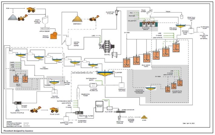
Source: Ausenco, 2023
| 1.15 | Project Infrastructure |
| 1.14.1 | Introduction |
Infrastructure existing for the mining and processing operations include can be seen in the site layout in Figure 1‑2.
| • | Underground mine, including portals (3), ramps and vents, |
| • | Roads: main access road, site access road, bridge crossing, borrow pit haul road, filtered tailings storage facility (FTSF) haul road, waster rock storage facility (WRSF) haul road, and explosives access road, |
| • | Diversion and collection channels, culverts, and containment structures, |
| • | Site main gate and guard house (2), |
| • | Accommodation camp, |
| |
| • | Power and water distribution, |
| • | Warehouse and truck shop, offices, medical clinic, and nursery, |
| • | Explosives magazines, |
| • | Process Plant, |
| • | Control room, |
| • | Doré room, |
| • | Assay laboratory (off-site facility), |
| • | Reagent storage facilities, |
| • | Water treatment plant, |
| • | Mineralized stockpiles and WRSFs, |
| • | Filtered tailings storage facility (FTSF), |
| • | Nuclear devices storage facility, |
| • | Hazardous waste interim storage facility, and |
| • | Exploration core shacks. |
| |
| Figure 1‑2: | Site Layout |
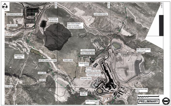
Source: Ausenco, 2023.
| |
| 1.14.2 | Waste Rock Storage Facility |
The two waste rock storage facilities (WRSF#1 and #2) have a combined capacity of 1.0 Mt and are expected to be sufficient as temporary facilities to store development waste before returning it to be used as rock fill in mined-out stopes.
| 1.14.3 | Ore Stockpiles |
The mineralized material stockpiles have a capacity of 0.35 Mt with segregated piles by grade (or clay content). These ore stockpiles are west of the crusher.
| 1.14.4 | Filtered Tailings Storage Facility |
The east filtered tailings storage facility (FTSF) was constructed based on the mine plan, and to avoid risks associated with storage of conventional slurried tailings behind a dam. Tailings are thickened, filtered, and delivered by trucks to the FTSF. Two facilities are designed to store 4.5 Mt of tailings. The East FTSF has been designed with a capacity to store up to 3.1 Mt of filtered tailings. Given the current estimated production for the LOM, 150 to 200 kt of filtered tailings are projected to be stored in the West FTSF, which will be constructed towards the end of the LOM.
The facilities were designed with an overall slope of 2.8:1 (H:V), slope between benches of 2.2:1 (H:V), and maximum approximate height of 56 m (measured from the lowest portion of the starting buttress to the maximum elevation of the dry stack). The East FTSF is 530 meters northeast of the Process Plant and covers 101,932 m2.
The FTSF designs include contact water collection channels, contact water collection/storage ponds, sub-drain collection systems, and access roads. Non-contact water diversion channels have been constructed to reduce the amount of surface contact water generated from the FTSF area.
| 1.14.5 | Power and Fuel |
Electrical power is supplied to site from the national grid, by way of an overhead power line, rated to carry 8.5 MVA at 33 kV. The connection to the grid is via the Nacozari de Garcia substation, which is 83 km from the operation.
Diesel fuel requirements for the mining equipment, process and ancillary facilities are supplied by permanent fuel distribution systems near the Process Plant.
| 1.14.6 | Camp |
The Las Chispas Operation is equipped with an accommodation camp with a capacity of 500 beds. The camp is connected to the national electricity grid and equipped with an emergency genset capable of handling the entire electrical load. The camp is serviced by a potable water treatment plant and sewage treatment plant. Garbage is collected on site and disposed of at the Arizpe municipality waste disposal facility.
All rooms are single occupancy and include a bed, toilet, air heating/conditioning and shower. The camp is equipped with kitchen and dining facilities to support the 24-hour operation, laundry, maintenance camp shop, and snack area. The camp also includes a gym, a multifunction sport field, a recreation facility, barbecue area, and a chapel.
| |
| 1.14.7 | Water Management |
Water required for the Las Chispas Operation is supplied as groundwater from dewatering of the underground mine and from the Sonora Valley groundwater, as required. The Las Chispas Operation design includes water diversion features to divert precipitation and groundwater away from operation infrastructure and direct it to natural receiving streams to minimize the generation of contact water. The layout also includes water collection ponds to collect any contact water that is produced, and to store any excess water from the underground workings such that it can be recycled for use in the Process Plant. There is not expected to be any water discharged from the Las Chispas Operation.
| 1.16 | Market Studies and Contracts |
The doré bars produced at the Las Chispas Operation have variable gold and silver contents and a variable gold to silver ratio, depending mainly on the corresponding gold and silver grades of the feed material being processed at any given time. Necessary arrangements have been made to safely transport, refine, and sell the doré.
Gold and silver doré can be readily sold on many markets throughout the world and the market price ascertained on demand.
Coeur uses a combination of historical and current contract pricing, contract negotiations, knowledge of its key markets from a long operations production record, short-term versus long-term price forecasts prepared by the company’s internal finance group, public documents, and analyst forecasts when considering long-term commodity price forecasts
| Element | Mineral Reserve Prices | Mineral Resource Prices | |
| Silver ($/oz) | 23.50 | 27.00 | |
| Gold ($/oz) | 1,800 | 2,100 |
Metal pricing for financial analysis was agreed upon based on consideration of various metal price sources. This included review of consensus price forecasts from banks and financial institutions, historic averages of spot prices, and current spot prices. The metal pricing for the base case economic model was:
The metal price forecasts used in the economic and cash flow analysis for gold varies from US$2,400 to US$2,700 per troy ounce payable and for silver varies from US$28.00 to US$30.00 per troy ounce payable.
At the Report Effective Date, necessary contracts and agreements necessary for operating Las Chispas have been entered int, including but are not limited to, contracts for drilling, underground mining, explosives, power, supply of consumables, catering and camp management, security, personnel transportation, and refining. These contracts are reviewed and negotiated periodically to ensure they remain competitive and aligned within industry norms for projects in similar settings in Mexico.
| |
| 1.17 | Environmental Studies, Permitting and Social or Community Impact |
| 1.16.1 | Environmental Considerations |
Environmental studies pertaining to the Las Chispas Operation have been submitted to the Ministry of Environmental and Natural Resources of Mexico (SEMARNAT), including physical and biological evaluations of the surrounding climate, flora, fauna, air quality, noise, and surface and groundwater quality. This information is updated and reported annually. In addition, a physical climate risk assessment aligned with the Task Force on Climate-Related Financial Disclosures (TCFD) was conducted in 2021 in order to assess and understand key risks.
LLA is conducting a comprehensive rock geochemicalty characterization study with the intent to assess the potential for acid rock drainage and metal leaching in the waste rock. Samples chosen based on the deposit's lithological characteristics are being processed by SGS Lakefield Canada, and the analysis is performed by a specialized consultant, with preliminary results due in 2025. This work will complement studies already completed which concluded on low concentration of potentially leachable metals and low risk of acid rock drainage (ARD).
There are no known environmental liabilities at the Las Chispas Operation arising from historic mining and processing operations. Since 2019 LLA has been conducting environmental characterization studies on soil and water, initially in the baseline study reported to SEMARNAT and subsequently periodically as part of the monitoring program. No environmental liabilities have been identified.
| 1.16.2 | Permitting Considerations |
LLA has successfully fulfilled the SEMARNAT's requirement for a suite of studies to support the award of environmental permits for the exploration, construction, and operation of the Las Chispas Operation. LLA secured all key permits in legal and environmental compliance for the Las Chispas Operation, including exploration, construction, exploitation stages, water use, change of land use, waste generation, emissions, and mineral processing.
A medium voltage power transmission line, authorized by SEMARNAT resulting in positive environmental impact, was developed and went operational in April 2022. The "Tetuachi" bridge was designed and constructed in 2021 to provide safe crossing over the Sonora River during the rainy season, with CONAGUA's approval.
LLA has a concession to exploit and use national groundwater for industrial mining use up to an authorized volume of 300,000 m3 /year, granted by CONAGUA in October 2020, and valid for 10 years (renewable). LLA also operates under a closed-circuit design for the Process Plant that eliminates the need for a wastewater discharge permit. LLA has a hazardous waste management plan registered with SEMARNAT.
LLA also maintains a general permit granted by SEDENA for the purchase, use, and storage of explosives, with plans for an increase in purchasing and storage capacity. Finally, the environmental operating license, secured from SEMARNAT in September 2022, permits operations at the Las Chispas Operation, integrating all previously obtained permits. Granted permits have varying terms, ranging from one year to unlimited terms. All permits will be renewed as required.
| |
| 1.16.3 | Environmental Management Plans |
LLA conducts a comprehensive Environmental Monitoring Program at the Las Chispas Operation, which includes routine studies on environmental noise, air quality, ground and surface water quality, drinking water analysis, and heavy metals in sediments, with annual reports presented to SEMARNAT. The Water Management Plan helps to ensure the efficient use of water resources by monitoring extraction and consumption quantities and avoids wasteful discharge practices. A third-party specialist is working on updating the water balance to improve resource optimization. The Air Quality Management Plan includes a mitigation program for fugitive dust caused by traffic operations, with measures like quarterly dust sampling, road irrigation, speed control, and preventive maintenance for mobile equipment, all being reported to SEMARNAT.
| 1.16.4 | Waste Considerations |
The Las Chispas Operation has been registered with SEMARNAT as a hazardous waste generator since 2019. A warehouse on site is maintained for the management and disposal of waste, including that produced by contractors, with waste disposal handled by SEMARNAT-authorized suppliers. LLA is also registered with the Commission of Ecology and Sustainable Development of the State of Sonora (CEDES) as a generator of special handling waste (non-hazardous), which is subject to recovery or recycling and is removed by state-authorized companies. LLA submits biannual reports to CEDES on the generation and disposal of this waste. All wastewater from Las Chispas Operation’s camp and office facilities is directed to a wastewater treatment plant, with a capacity of up to 90 m3 treated effluent per day; this treated water is used for road irrigation to suppress dust and the greening of reforested areas.
| 1.16.5 | Social and Community Considerations |
The Sonora Valley is an isolated community set in a region of rugged topography. As of March 2023, the Las Chispas Operation personnel consisted of 908 personnel (327 employees of Llamarada and 581 contractors). 15% of the personnel were local to the Sonora Valley and 99% of the total number were from various parts of Mexico. There are four main ejido groups, three of which will be impacted by mining operations (Ejido Bamori, Ejido Arizpe, and Ejido Sinoquipe) and the fourth (Ejido Los Hoyos) is impacted by the Los Hoyos Powerline. Community engagement and relationship management plays a crucial role in Las Chispas Operations. As such, ongoing dialogue is maintained, and regular meetings held with the communities within the areas of influence including the four main ejido groups. The potential for impacts to Indigenous populations were considered; however, no Indigenous populations were identified within 10 km of the Las Chispas Operation.
A Social Baseline Study and a Materiality Assessment highlighted key concerns within the community including water scarcity, environmental safety, local infrastructure, and job opportunities. A community communication strategy and grievance mechanism was established in response to these concerns and $1.5 million has been committed to improving local water infrastructure over five years (2022 - 2026). Furthermore, the Las Chispas Operations ia also a part of the Sonoran Mining Cluster, sharing best practices on community relations and responsible mining.
The Las Chispas Operations is one of the main sponsors of Impulso Koria, a non-profit organization focusing on local infrastructure, education, and healthcare. In addition, Las Chispas Operations has incorporated a ranching business, Babicanora Agrícola del Noroeste S.A de C.V (BAN), underlining their participation in the local economy and commitment to the local communities.
| |
| 1.16.6 | Closure Considerations |
A Conceptual Closure Plan was prepared in accordance with applicable Mexican standards. Under Mexican law, mining may be initiated under a Conceptual Closure Plan with a Detailed Closure Plan being developed later in the operation’s life.
A conceptual closure cost estimate was prepared for the Las Chispas Operation, using a combination of the following: information derived from the 2021 FS Report, drone imagery of existing facilities and landforms, information from the Detailed Engineering Phase 1 FTSF Design, a database of itemized costs from local contractors working on similar projects in the area, and assumptions derived from WSP’s experience in mine closure. The estimated cost is $11.9 million. Closure costs are assumed to be incurred over a period of three years, following the cessation of production and a subsequent period of seven years of monitoring.
| 1.18 | Sustaining Capital and Operating Costs |
| 1.17.1 | Sustaining Capital Cost Estimates |
Capital cost estimates are at a minimum at pre-feasibility level of confidence, having an accuracy level of ±25% and a contingency range not exceeding 15%.
LOM sustaining capital costs total $163.1 M from January 1, 2025, which are detailed as per Table 1‑4.
| Calendar Year | LOM | 2025 | 2026 | 2027 | 2028 | 2029 | 2030 | 2031 | |
| Production Year | 1 | 2 | 3 | 4 | 5 | 6 | 7 | ||
U/G Mine Development | 139.3 | 30.6 | 31.4 | 29.8 | 20.6 | 15.1 | 11.8 | - | |
U/G Mine Infrastructure | 14.9 | 3.8 | 6.1 | 1.7 | 2.1 | 1.2 | - | - | |
Process Plant | 4.0 | 1.9 | 0.5 | 0.5 | 0.5 | 0.5 | - | - | |
Other Sust. & Dev. | 0.6 | - | - | - | 0.3 | - | 0.3 | - | |
G&A (including mobile) | 4.3 | 1.1 | 0.8 | 0.8 | 0.8 | 0.8 | - | - | |
| Total | 163.1 | 37.5 | 38.8 | 32.8 | 24.3 | 17.6 | 12.1 | - | |
| 1.17.2 | Reclamation and Closure Cost Estimates |
An allowance of $11.9 M was made for closure costs with spending scheduled to occur across the three years following the cessation of production. Any change in regulations that would require the Company to undertake progressive closure, or to post a cash bond, would affect the timing of these cash flows.
No salvage value was assumed for the Process Plant and surface infrastructure. It has also been assumed that CFE would accept ownership of the power line which is common in Mexico.
| |
| 1.17.3 | Operating Cost Estimate |
Operating cost estimates are at a minimum at pre-feasibility level of confidence, having an accuracy level of ±25% and a contingency range not exceeding 15%.
The average LOM operating cost is estimated at 176.95$/t processed. The operating cost is defined as the total direct operating costs including mining, processing, and G&A costs. Mining costs are estimated to be 110.29 $/t processed (114.17 $/t mined). Tonnes of material to be processed includes mined ore that is already in stockpiles. Table 1‑5 shows a summary breakdown of the operating costs.
| Area | LOM Average Operating Cost | |
| Mining* ($/t processed) | 110.29 | |
| Process ($/t processed) | 42.05 | |
| G&A ($/t processed) | 24.61 | |
| Total LOM Operating Cost ($/t processed) | 176.95 | |
Notes: *Includes stope development but excludes capitalized underground development. Total may not add due to rounding.
| 1.19 | Economic Analysis |
A pre- and post-tax economic analysis was completed on the basis of a discounted cash flow model featuring a 5% discount rate. The analysis used constant (real) Q4 2024 US$ and the Las Chispas Operation cash flows were modelled in annual periods. Operating and capital cost estimates are at a minimum at pre-feasibility level of confidence, having an accuracy level of ±25% and a contingency range not exceeding 15%.
The model assumed a production period of seven years, including 2025-2031. The plan assumes a stockpile balance for the entire LOM and a max mill throughput of 1,250 t/d. This mill rate was chosen because it has been proven sustainable and does not require a ramp up in current mining development rates to maintain this throughput through the LOM.
The economic model was based on a 2025 gold price of $2,700/oz and a silver price of $30.00/oz with prices declining yearly and flattening out at gold price of $2,400/oz and a silver price of $28.00 in 2029. The refining terms used as the basis of the economic analysis are based on the actual average cost paid by the Company to a third-party refiner. The freight terms are also based on actual rates.
Taxes were built into the financial model and include a 30% corporate income tax, a mining tax of 8.5% of EBITDA, and a precious metals mining tax on 1% NSR.
The economic analysis demonstrates that the mine plan has positive economics under the assumptions used. The Las Chispas Operation post-tax (NPV) at a 5% discount rate is estimated to be $538.6 M. A summary of the economic analysis of the Las Chispas Operation is shown in Table 1‑6.
| |
Table 1‑6: | Economic Analysis Summary |
| Description | Unit | LOM Total/Avg. | |
| Average Mill Throughput | t/d | 1,250 | |
| Mine Life years | years | 7 | |
| Average Gold Mill Head Grade | g/t Au | 3.51 | |
| Average Silver Mill Head Grade | g/t Ag | 329.6 | |
| Average Silver Equivalent Mill Head Grade | g/t AgEq | 632.5 | |
| Contained Gold in Mine Plan | koz Au | 356.6 | |
| Contained Silver in Mine Plan | koz Ag | 33,516.4 | |
| Contained Silver Equivalent in Mine Plan | (koz AgEq) | 64,319.4 | |
| Average Gold Metallurgical Recovery | % Au | 98.0 | |
| Average Silver Metallurgical Recovery | % Ag | 97.5 | |
| Payable Gold | koz Au | 349.0 | |
| Payable Silver | koz Ag | 32,645.9 | |
| Payable Silver Equivalent | koz AgEq | 62,787.5 | |
| Average Full Year Annual Production (Years 1-5) | |||
| Gold | Au koz/yr | 53.1 | |
| Silver | Ag koz/yr | 5,259.1 | |
| Silver Equivalent | AgEq koz/yr | 9,843.7 | |
| Mining Cost | $/t mined | 114.17 | |
| Mining Cost | $/t processed | 110.29 | |
| Process Cost | $/t processed | 42.05 | |
| G&A Cost | $/t processed | 24.61 | |
| Total Operating Cost | $/t processed | 176.95 | |
| LOM Sustaining Capital Cost | $M | 163.1 | |
| Closure Costs | $M | 11.9 | |
| Cash Costs LOM – Mine Level | $/oz AgEq | 9.42 | |
| Au Price (LOM Average) | $/oz | 2,493 | |
| Ag Price (LOM Average) | $/oz | 28.86 | |
| Undiscounted LOM net free cash flow | $M | 626.4 | |
| Pre-Tax NPV (5%) | 5%, $M | 853.0 | |
| Post-Tax NPV (5%) | 5%, $M | 538.6 | |
The Las Chispas Operation is most sensitive to metal pricing and grade.
| 1.20 | Recommendations |
A sequential phase approach is presented for recommended future work. The following is the budget for the exploration and development activities recommended to be completed in 2025.
| |
Table 1‑7: | Summary of Budget for Recommended Phase 1 and Phase 2 |
| Exploration and Development Activity | Cost Estimate ($M) 2025 | |
| Exploration and Mineral Resource Conversion Drilling (74,800 m) | 14.50 | |
| QA/QC | 0.10 | |
| Bulk Density Investigation | 0.03 | |
| Resource Estimation | 0.10 | |
| Mine Design | 0.10 | |
| Sub-Total | 14.80 | |
| Contingency (10%) | 1.50 | |
| Total | 16.30 |
Note: Numbers may not add due to rounding.
| |
| 2 | INTRODUCTION |
| 2.1 | Introduction |
Coeur Mining, Inc. (Coeur Mining or the Company) is listed on the New York Stock Exchange (NYSE). As a result, Coeur Mining is a registrant with the United States Securities and Exchange Commission (SEC) and must comply with the subpart 229.1300 – Disclosure by registrants Engaged in Mining Operations of Regulation S-K (S-K 1300).
Coeur Mining commissioned Ausenco Engineering ULC. (Ausenco) to complete a Technical Report (the Report) prepared in accordance with S-K 1300 on the Las Chispas Operation (the Las Chispas Operation), located in Sonora, Mexico for the purposes of the Company’s acquisition of SilverCrest Metals Inc (SilverCrest). The effective date (the Effective Date) for the Report is December 31, 2024.
The Las Chispas Operation is held in the name of Coeur’s wholly owned subsidiary, Compañía Minera La Llamarada S.A. de C.V.
| 2.2 | Report Purpose |
The report was prepared to be attached as an exhibit to support mineral property disclosure, including mineral resource and mineral reserve estimates for the Las Chispas Operation in Coeur Mining’s Form 10-K for the year ended December 31, 2024.
| 2.3 | Terms of Reference |
The firms and consultants who are providing Qualified Persons (QPs) responsible for the content of the Report are, in alphabetical order, Ausenco Engineering Canada ULC (Ausenco), P&E Mining Consultants Inc. (P&E). Christopher Pascoe, RM SME, and Joseph Wallick, RM SME.
The Report presents Mineral Resource and Mineral Reserve Estimate for the Las Chispas Operation, and an economic assessment based on ongoing underground mining operations and a conventional processing circuit that produces gold-silver doré bars.
All units of measurement in the Report are metric, unless otherwise stated.
The monetary units are in US dollars, unless otherwise stated.
Mineral Resources and Mineral Reserves are reported in accordance with S-K 1300.
| 2.4 | Site Visits and Scope of Personal Information |
Mr. Murray, representing Ausenco, completed a site visit from March 14-16, 2023. The objectives of the site visit were to develop an understanding of the Las Chispas Operations including plant infrastructure and process facilities, and to observe actual operations and operating results.
| |
Mr. Burga, representing P&E, last conducted a site visit from December 3-4, 2024. The purpose of this visit was to complete sampling of selected drill holes for assay data verification, check the location of select surface and underground drill collars and channel sampling sites, complete an underground tour, and meet with Las Chispas Operations technical staff on-site. Thirty-two (32) samples were collected from nine drill holes during the site visit for verification of the assay data.
Mr. Pascoe, representing Coeur, last visited the site from January 13-16, 2025. The objective of the visit was to inspect the mine, process plant, infrastructure, operating practices, 2025 budgets and to confirm inputs utilized in the cost estimates, economic analysis.
Mr. Wallick, representing Coeur, conducted a site visit from January 13-16, 2025. The visit's objective was to inspect the mine, operating practices, mine engineering practices, and to confirm inputs used in the reserves and mining methods.
| 2.5 | Information Sources and References |
Reports and documents listed in Section 2.7 and Section 24 and 25 were used to support its preparation. Additional information was sought from Las Chispas Operations personnel where required.
| 2.6 | Previous Technical Reports |
There have been no Technical Report Summaries previously completed for this project under S-K 1300.
The following historical technical reports have been prepared under NI-43-101 on the Las Chispas Operation:
| • | Murray, K., Weston, S., Marthinus Marx, W., Langlais, P., Verreault, M., Peacock, B., Barry, J., Burga, D., Puritch, E., Stone, W., Wu, Y., Lee, C. and Preciado, H.F., 2023, Las Chispas Operation Technical Report, for SilverCrest Metals Inc., Effective date: July 19, 2023, Report Date: September 5, 2023. |
| • | Kalanchey, R, Weston, S., Stone, W., Puritch, E., Burga, D., Barry, J., Wu, Y., Turner, A.J., Michaud, C., Verreault, M., Aref, K., and Preciado, H., 2021, NI 43-101 Technical Report & Feasibility Study on the Las Chispas Project, Sonora, Mexico, for SilverCrest Metals Inc., Effective date: January 4, 2021. |
| • | Barr, J., Ghaffari, H., and Horan, M., 2019: Technical Report and Preliminary Economic Assessment for the Las Chispas Property, Sonora, Mexico: report prepared by Tetra Tech Canada Inc. for SilverCrest Metals Inc., effective date May 15, 2019, amended July 19, 2019. |
| • | Barr, J., and Huang, J., 2019: Technical Report and Mineral Resource Estimate for the Las Chispas Property, Sonora, Mexico: report prepared by Tetra Tech Canada Inc. for SilverCrest Metals Inc., effective date February 8, 2019. |
| • | Fier, N.E., 2018: Technical Report and Updated Mineral Resource Estimate for the Las Chispas Property, Sonora, Mexico: report prepared for SilverCrest Metals Inc., effective date September 13, 2018. |
| • | Barr, J., 2018: Technical Report and Mineral Resource Estimate for the Las Chispas Property, Sonora, Mexico: report prepared by Tetra Tech Canada Inc. for SilverCrest Metals Inc., effective date February 12, 2018, amended May 9, 2018. |
| |
| • | Barr, J., 2016: Technical Report on the Las Chispas Property, Sonora, Mexico: report prepared by Tetra Tech Canada Inc. for SilverCrest Metals Inc., effective date September 15, 2016. |
| 2.7 | Units and Abbreviations |
| Table 2‑1: | Unit Abbreviations |
| Abbreviation | Description | ||
$ | United States dollar | ||
MXN | Mexican peso | ||
°C | degree Celsius | ||
°F | degree Fahrenheit | ||
% | percent | ||
μ | micro | ||
μm | micrometer | ||
C$ | Canadian dollar | ||
cm | centimeter | ||
CN | Free Cyanide in solution | ||
ft | feet | ||
ft2 | square feet | ||
g | gram | ||
g/t | grams per metric tonne | ||
ha | hectare | ||
hr | hour | ||
HP | horsepower | ||
km | kilometer | ||
koz | thousand ounces | ||
kV | kilovolt | ||
kg/t | kilo grams per tonne | ||
kW | kilowatt | ||
kWh | kilowatt-hour | ||
kWh/t | kilowatt-hours per metric tonne | ||
kN/m3 | kilonewton per cubic meter | ||
MW | megawatt | ||
kPa | kilopascal | ||
kcmil | thousand circular mills | ||
kN | kilonewton | ||
masl | meters above sea level |
| |
| Abbreviation | Description | ||
| mamsl | meters above mean sea level | ||
L/s | litre per second | ||
M | million | ||
m | meter | ||
m/a | meters per annum | ||
m/d | meters per day | ||
m2 | square meter | ||
m3 | cubic meter | ||
mm | millimeters | ||
t | metric tonne | ||
Mt | million tonnes | ||
oz | ounce | ||
Moz | million ounces | ||
Mt | mega tonne | ||
ppb | parts per billion | ||
ppm | parts per million | ||
ton | short ton | ||
t/h | metric tonnes per hour | ||
t/d | metric tonnes per day | ||
t/a | metric tonnes per annum | ||
w/w/ w/s | gravimetric moisture content (weight of water/weight of soil) | ||
wt | weight |
| Table 2‑2: | Name Abbreviations |
| Abbreviation | Description | ||
3D | three-dimensional | ||
AAS | atomic absorption spectroscopy | ||
ABA | acid base accounting | ||
AES | atomic emission spectrometry | ||
AgEq | silver equivalent | ||
ALS | ALS Chemex | ||
ARD | acid rock drainage | ||
BAC | Babi Central | ||
BAM | Babi | ||
BAN | Babicanora Agrícola Del Noroeste S.A de C.V | ||
BAV | Babi Vista | ||
CCD | counter-current decantation | ||
| CCTV | closed circuit television |
| |
| Abbreviation | Description | ||
CDN Labs | CDN Resource Laboratories Ltd. | ||
CEDES | Comisión de Ecología y Desarrollo Sustentable del Estado de Sonora (Commission of Ecology and Sustainable Development of the State of Sonora, Mexico) | ||
CFE | Comisión Federal de Electricidad (Federal Electricity Commission of Mexico) | ||
CMT | construction management team | ||
CNCF | cumulative cash flow | ||
COG | cut-off grade | ||
CONAGUA | Comisión Nacional del Agua (National Water Comission of Mexico) | ||
CPI | consumer price index | ||
CRF | cemented rock fill | ||
CRM | certified reference materials | ||
CSR | corporate social responsibility | ||
CSS | closed side setting | ||
CSV | comma-separated value | ||
DCS | distributed control system | ||
DSO | Deswik Stope Optimizer software | ||
EBITDA | earnings before interest, taxes, depreciation and amortization | ||
ELOS | equivalent linear overbreak/slough | ||
EPCM | Engineering, Procurement and Construction Management | ||
ESG | Environmental, Social and Governance | ||
ESMS | environmental and social management system | ||
FA | fire assay | ||
FTSF | filtered tailings storage facility | ||
FW | footwall | ||
G&A | General and Administration | ||
GIS | geographic information system | ||
GPS | global positioning system | ||
HDPE | high density polyethylene | ||
HR | hydraulic radius | ||
HRI | Hydro-Ressources Inc. | ||
HW | hangingwall | ||
ICP | inductively coupled plasma | ||
ID | inverse distance | ||
ID3 | inverse distance weighting to the third power | ||
IP | Preventive Report (Informe Preventivo) | ||
| IRR | internal rate of return | ||
LAN | local area network |
| |
| Abbreviation | Description | ||
LiDar | light detection and ranging data | ||
LLA | Compañía Minera La Llamarada S.A. de C.V (subsidiary of Coeur Mining in Mexico) | ||
LOM | life of mine | ||
LRS | longhole retreat stoping | ||
MC-HS | master composite historic stockpile | ||
MED Comp | medium grade composite | ||
MGM | mine general manager | ||
MIA | Spanish acronym for Environmental Impact Assessment | ||
ML | metals leaching | ||
MS | mass spectrometry | ||
MSO | Mineable Shape Optimizer software | ||
N’ | stability number | ||
NAF | non-acid forming | ||
NAG | net acid generation | ||
NCF | net cash flow | ||
NN | nearest neighbor | ||
NPV | net present value | ||
NW | northwest | ||
OEM | original equipment manufacturer | ||
OIS | operator interface station | ||
ORP | operation readiness plan | ||
P&E | P&E Mining Consultants Inc. | ||
PCR | polymerase chain reaction | ||
PEA | preliminary economic analysis | ||
PEP | project execution plan | ||
PLS | pregnant leach solution | ||
PMZ | precious metal zone | ||
Q (1, 2, 3, 4) | calendar quarter (1, 2, 3, 4) | ||
Q’ | mass quality | ||
QA/QC | quality assurance/quality control | ||
QEMSCAN | quantitative evaluation of materials by scanning electron microscopy | ||
QP | Qualified Person | ||
RDCLF | rhyodacitic crystal tuff | ||
ROM | run of mine | ||
RPD | relative percent difference | ||
RQD | rock quality designation | ||
SAG | semi-autonomous grinding |
| |
| Abbreviation | Description | ||
SD | standard deviation | ||
SEDENA | Secretaría de la Defensa Nacional (Ministry of Defense) | ||
SEMARNAT | Secretaría del Medio Ambiente y Recursos Naturales (Ministry of Environment and Natural Resources of Mexico) | ||
SG | specific gravity | ||
SGS Lakefield | SGS Lakefield Research | ||
SilverCrest or SIL | SilverCrest Metals Inc. | ||
SLS | solid to liquid system | ||
SUCS | Unified Soil Classification System | ||
SWIR | shortwave infrared | ||
SWMS | Safe Work Method Statement | ||
URF | Uncemented Rock Fill | ||
USMCA | United States-Mexico-Canada Agreement | ||
UTM | Universal Transverse Mercator | ||
VHF | very high frequency | ||
VOIP | voice over internet protocol | ||
VSA | vacuum swing adsorption | ||
WGS | World Geodetic System |
Table 2‑3: | Definitions |
| Term | Definition | ||
Las Chispas Property | this encompasses all mineral occurrences and land underlying the mineral concessions 100% owned or optioned to Coeur Mining. | ||
Las Chispas District | this is a general term used in historic context for the various mines which operated in the area prior to the 1930s. The district has an approximate footprint of 4 km north to south and 3 km east to west. It consists of the Las Chispas Area and Babicanora Area, which are 1.5 km apart | ||
Las Chispas Area | this consists of the Las Chispas Vein containing Area 118 Zone and Historic Mine, Giovanni Vein, Gio Mini Vein, La Blanquita Vein, William Tell Vein, Luigi Vein, Luigi FW Vein, Varela veins, Chiltepin veins, El Cumaro Vein, and various other lesser or unnamed veins | ||
Babicanora Area | this consists of the Babicanora Main Vein containing Area 51 Zone and Babicanora Central Zone, Babicanora FW Vein, Babicanora HW Vein, Babi Vista Vein, Babi Vista FW Vein, Babi Vista Vein Splay, Babicanora Norte Vein containing Area 200 Zone, Babicanora Norte HW Vein, Babicanora Sur Vein, Babicanora Sur HW Vein, Amethyst Vein, La Victoria Vein, Granaditas Vein, Granaditas Dos Vein, Ranch Veins and various other lesser or unnamed veins | ||
Area 118 Zone (Area 118) | the southeast extension of the Las Chispas Vein discovered in 2020 by drill hole LC20-118. The hole intersected 8.6 m (true width) grading 44.30 g/t gold and 4,551.5 g/t silver | ||
Area 51 Zone (Area 51) | the southeast extension of the Babicanora Main Vein discovered in late 2017 by drill hole BA17-51. The hole intersected 3.1 m (true width) grading 40.45 g/t gold and 5,375.2 g/t silver |
| |
| Term | Definition | ||
| Babicanora Central Zone (Babicanora Central) | the northwest, near surface, extension of the Babicanora Main Vein | ||
Area 200 Zone (Area 200) | the southeast extension of the Babicanora Norte Vein discovered in 2020 by drill hole BA219-200. The hole intersected 2.0 m (true width) grading 39.77 g/t gold and 3,472.5 g/t silver | ||
The Las Chispas (Historic) Mine | |||
Vein | this is a current term used by Coeur for geological features consisting of semi-continuous structures, quartz veins, quartz stockwork, and breccia |
| 2.8 | Reporting of Grades by Silver Equivalent |
The Silver Equivalent ratio used to calculate equivalent silver in the financial evaluation was variable based on the metal price utilized for each year as described in Section 16 and averaged 86.38:1 (silver to gold ratio) over the 7-year LOM and this is used for reporting purposes only in the financial evaluation, and not for the calculation of revenue or other financial metrics.
Silver equivalent grades have been used in the cut-off grade calculations for the Mineral Resource and Mineral Reserve estimates and the details of these calculations may be seen in Section 11.13 and Section 12.4.
| |
| 3 | PROPERTY DESCRIPTION AND LOCATION |
| 3.1 | Introduction |
The Las Chispas Property (Figure 3‑1) is located in the State of Sonora, Mexico, and is centred at approximate 30.233902°N latitude and 110.163396°W longitude (Universal Transverse Mercator [UTM] World Geodetic System [WGS]84: 580,500E, 3,344,500N), within the Arizpe Mining district. The City of Hermosillo is 220 km, or a three-hour drive to the southwest; Tucson, Arizona (USA) is 350 km via Cananea, or a five-hour drive, to the northwest; and the community and Cananea Mine are located 150 km, or a two-and-a-half-hour drive, to the north along Highway 89. The general topography of the area surrounding Las Chispas is shown in Figure 3‑1. A location map for the Property is shown in Figure 3‑2. The Property area is covered by 1:50,000 topographic map sheet “Banamichi” H12-B83.
| 3.2 | Project Ownership |
Compañía Minera La Llamarada S.A. de C.V. (LLA) is a wholly-owned subsidiary of Coeur Mining holds title to the mining concessions comprising the Las Chispas Property.
Figure 3‑1: | View Across the Las Chispas Property (View Looking Eastwards) |

Source: Modified by SilverCrest (2024) from Tetra Tech Canada Inc., 2019
Note: Length of field of view in photograph is 4 km.
| |
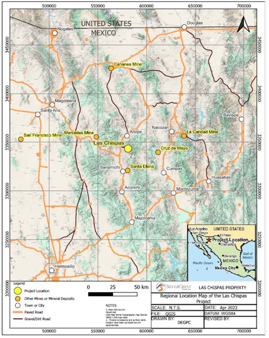
Source: Modified by SilverCrest (2024) from Barr et al., 2019
| |
| 3.3 | Mineral Tenure |
The Las Chispas Property consists of 27 mineral concessions, totalling 1,414 ha, as shown in Figure 3‑3 and listed in Table 3‑1. LLA, has acquired 100% title to the mining concessions comprising the Las Chispas Property, except for the Lopez and Panuco II (cancelled) mining concessions.

Source: SilverCrest (2024)
| |
Table 3‑1: | Mineral Concessions of the Las Chispas Operations Property1 |
Concession Name | Title Number | Registration Date | End Date | Surface Area (ha) | Concession Holder | Liens or Legal Affectations | Status |
| El Bervano Fracción 1 | 212027 | 8/25/2000 | 8/24/2050 | 53.4183 | LLA | not free | active |
| El Bervano Fracción 2 | 212028 | 8/25/2000 | 8/24/2050 | 0.9966 | LLA | not free | active |
| Las Chispas Uno | 188661 | 11/29/1990 | 11/28/2040 | 33.711 | LLA | not free | active |
| El Siete | 184913 | 12/6/1989 | 12/5/2039 | 43.239 | LLA | not free | active |
| Babicanora Grande | 159377 | 10/29/1973 | 10/28/2073 | 16.00 | LLA | not free | active |
| Fernandez Leal | 190472 | 4/29/1991 | 4/28/2041 | 3.1292 | LLA | not free | active |
| Guillermo Tell | 191051 | 4/29/1991 | 4/28/2041 | 5.6521 | LLA | not free | active |
| Limantour | 191060 | 4/29/1991 | 4/28/2041 | 4.5537 | LLA | not free | active |
| San Gotardo | 210776 | 11/26/1999 | 11/25/2049 | 3.6171 | LLA | not free | active |
| Las Chispas | 156924 | 5/12/1972 | 5/11/2072 | 4.47 | LLA | not free | active |
| Espíritu Santo Fracc. I | 217589 | 8/6/2002 | 8/5/2052 | 733.3232 | LLA | not free | active |
| Espíritu Santo Fracc. II | 217590 | 8/6/2002 | 8/5/2052 | 0.877 | LLA | not free | active |
| Cruz | 223784 | 2/15/2005 | 2/14/2055 | 14.436 | LLA | not free | active |
| Lopez | 190855 | 4/29/1991 | 4/28/2041 | 1.7173 | Jose Cruz López Mejía (34%), Eliseo Espina Guillen (33%), Jesús Cruz López ( 33%) | not free | active |
| Nuevo Babicanora Fracc. I | 235366 | 11/18/2009 | 11/17/2059 | 392.576 | LLA | not free | active |
| Nuevo Babicanora Fracc. II | 235367 | 11/18/2009 | 11/17/2059 | 9.8115 | LLA | not free | active |
| Nuevo Babicanora Fracc. III | 235368 | 11/18/2009 | 11/17/2059 | 2.2777 | LLA | not free | active |
| Nuevo Babicanora Fracc. IV | 235369 | 11/18/2009 | 11/17/2059 | 3.6764 | LLA | not free | active |
| Nuevo Lupena | 212971 | 2/20/2001 | 2/19/2051 | 13.083 | LLA | not free | active |
| La Victoria | 216994 | 6/5/2002 | 6/4/2052 | 24.00 | LLA | not free | active |
| Las Chispas 3-A | 245423 | 01/24/2017 | 01/23/2067 | 1.0809 | LLA | not free | active |
| Las Chispas 3-B | 245424 | 01/24/2017 | 01/23/2067 | 0.3879 | LLA | not free | active |
| Las Chispas 3-C | 245425 | 01/24/2017 | 01/23/2067 | 0.3413 | LLA | not free | active |
| Las Chispas 3-D | 245426 | 01/24/2017 | 01/23/2067 | 0.3359 | LLA | not free | active |
| Las Chispas 3-E | 245427 | 01/24/2017 | 01/23/2067 | 0.4241 | LLA | not free | active |
| Las Chispas 3-F | 245428 | 01/24/2017 | 01/23/2067 | 5.6112 | LLA | not free | active |
Panuco II2 | 193297 | cancelled | Cancelled | 12.9286 | Adelaido Gutierrez Arce | not free | cancelled |
| Total (27) | - | - | - | 1,413.76 | - | - | - |
Notes: As of December 31, 2024, Date of the Opinion for Las Chispas by EC RUBIO for Coeur Mining Inc. Panuco II has been overstaked by a new mining concession that is filed and currently under review by the Mining Authority.
| |
Mining duties are based on the surface area and date of issue of each concession and are due in January and July of each year at a total annual cost of $10,000 (adjusted scale). At the Report Effective Date, all required mining duties were paid.
| 3.4 | Mineral Reserves on Mining Concessions |
All Mineral Reserves stated in the Report are on mining concessions 100% owned by LLA with no NSR applied. All mining concessions are 100% owned by LLA except for those noted and described below.
| 3.4.1 | Option 1 |
On February 21, 2018, LLA acquired from Minerales Tarachi, S. de R.L. de C.V. an option to purchase the rights to the La Fortuna mining concession applications No. 082/39410 and 082/38731, which cover the Panuco II and Carmen Dos Fracción II mineral lots on payment of MXP500,000 (paid) and $150,000 payable on acquisition of title by LLA
(Title Opinion dated May 15, 2023). Title transfer of concessions are pending until the applications are issued as mining concessions
| 3.4.2 | Option 2 |
On January 10, 2017, Pedro Antonio Goya Espina and Eliseo Espina Guillen, acting as Assignors, and LLA, acting as Assignee, signed certain Partial Assignment of Mining Concession Agreement for transfer to the Assignee of 67% title to the Lopez mining concession. Acquisition by LLA of 67% title to the Lopez concession is subject to a condition precedent consisting in the exercise or relinquishment of right of first refusal of owner of remaining 34% title.
| 3.4.3 | Option 3 |
On December 1, 2018, LLA acquired 100% rights to Panuco II, pending title for ownership. This concession was cancelled in 1999 but, by law, a public notice of cancellation was not announced, therefore, a legal recourse for reinstatement was filed by LLA. The Panuco II area has been overstaked by La Fortuna, which is currently under review by the Mining Authority.
All Mineral Reserves stated in the Report are on mining concessions 100% owned by LLA with no NSR applied.
| 3.5 | Surface Rights |
The surface rights overlying the Las Chispas mineral concessions and road access from local highway are either owned by LLA or held by LLA under a negotiated 20-year lease agreement. Surface rights are sufficient for the LOM plan and include the locations of necessary infrastructure as presented in the Report.
| 3.5.1 | Ejido Bamori |
On November 18, 2015 (as amended June 3, 2018), LLA signed a 20-year lease agreement with the Ejido Bamori for surface access and use of facilities. Compensation for exploration activities was paid at a rate of MXN700/ha, up to a total of 360.60 ha. After exploration and announcement of mine construction/production, compensation was paid on a scaled timeframe at a rate of MXN2,000/ha during construction and will continue for Years 1 to 4 of production. After the fifth production year to the end of the mine life the compensation will be MXN4,000/ha. In April 2019, LLA expanded its Ejido Bamori surface rights from 360.6 ha to 400.0 ha.
| |
| 3.5.2 | Cuesta Blanca Ranch |
In February 2018, LLA purchased the Cuesta Blanca Ranch covering 671.9 ha of land situated in the municipality of Arizpe, Sonora.
| 3.5.3 | Babicanora Ranch |
In April 2017, LLA purchased from Maprejex Distributions Mexico, S.A. de C.V. the Babicanora Ranch covering 2,500 ha of land situated in the municipality of Arizpe, Sonora.
| 3.5.4 | Tetuachi Ranch |
In November 2017, LLA signed a lease agreement for a term of 20 years with Maria Dolores Pesqueira Serrano for the lease of the Tetuachi Ranch covering 32.3 ha of land situated in Arizpe, Sonora, for payment of an annual rental fee of MXN2,000/ha during the exploration phase and MXN7,000/ha during the exploitation phase.
| 3.5.5 | La Higuerita Ranch |
On February 2, 2023, LLA purchased the La Higuerita Ranch situated in the municipality of Arizpe, Sonora.
| 3.6 | Royalties |
A 2% NSR royalty is payable to Gutierrez-Pérez-Ramirez, on the Nuevo Lupena and Panuco II concessions for material that has processed grades of ≥0.5 oz per tonne gold and ≥40 oz per tonne silver combined (EC Rubio Legal Title Opinion dated December 31, 2024). Currently no Mineral Reserves are estimated within these concessions.
| 3.7 | Permitting Considerations |
Permitting considerations for operations are discussed in Section 17.
| 3.8 | Environmental Considerations |
Environmental considerations for operations are discussed in Section 17.
Remnants exist on the Las Chispas Operation that show the active mining history and community development that once existed in this district. There are numerous historic mine portals and shafts that are partially overgrown with vegetation, which have been flagged and/or fenced.
| 3.9 | Social License Considerations |
Social license considerations for operations are discussed in Section 17.
| 3.10 | Comment on Property Description and Location |
To the extent known to the QP, there are no other significant factors, encumbrances or risks that may affect access, title, or the right or ability to perform work on the Las Chispas Operation that have not been discussed in this Report.
| |
| 4 | ACCESSIBILITY, CLIMATE, LOCAL RESOURCES, INFRASTRUCTURE AND PHYSIOGRAPHY |
| 4.1 | Accessibility |
The Las Chispas Operation is accessed via paved Highway 89 from the communities of Arizpe (12 km away) and Banamichi (25 km away). The Las Chispas Operation itself is accessed via secondary gravel road, 10 km from the paved highway. The Rio Sonora crossing is possible via the Tetuachi Bridge, recently constructed by Las Chispas Operations (Figure 4‑1). The bridge provides single lane access across the Sonora River.
| Figure 4‑1 | Tetuachi Bridge |

Source: SilverCrest, 2024.
The 10 km gravel road was upgraded during construction to facilitate construction and operation activities. Net elevation gain from the highway to the Operation area is 400 m.
| |
| 4.2 | Climate |
The climate for the Sonoran Desert, with a dry season from October to May. Seasonal temperatures vary from 0° to 40°C. Average rainfall is estimated at 300 mm/year. There are two wet seasons: one in the summer (July to September) and the second in the winter (December). The summer rains are short with heavy thunderstorms, whereas the winter rains are longer and lighter. Summer afternoon thunderstorms are common and can temporarily impact electrical services. Experience to date has shown these power interruptions are of short duration. Operations are being conducted year-round.
| 4.3 | Local Resources and Infrastructure |
| 4.3.1 | Water Supply |
Water requirements range between 8 and 12 L/s for the operation stage. The requirement varies between seasons. Core drilling for exploration purposes adds to this requirement, depending on number of active rigs. Water wells have been established to supply local ranches. During previous geophysical investigation, areas near the Las Chispas Operation were surveyed, but significant surface water-bearing targets were not identified.
Water for the Las Chispas Operation is pumped from two main sources. First, from the 900 level (feet from surface or 850 m above sea level (masl)) of the historical Las Chispas Mine. This water source is considered part of the regional water table, which is linked by a pumping system to seven surface water storage tanks adjacent to the Process Plant site (Figure 4‑2). The second source of water is located in the Sonora Valley Basin within the Property limit and near the main access road to the site. Together, the two sources of water are adequate in quantity and quality to support production and exploration activities. The second pumping station (Figure 4‑3) in the Sonora Valley Basin (10 km from site) is powered from the nearby 33 kV powerline.
| |
| Figure 4‑2: | Water Distribution Tank Located Near the Main Office |

Source: SilverCrest, 2024.
| |
Figure 4‑3: | Sonora River Pumping Station |

Source: SilverCrest, 2024.
The water management plan defines the order of priority to service the operation, with a view to reduce the impact on the surrounding environment. First, water is pumped from contact water in the 3 ponds located on the surface (Figure 4‑4 to Figure 4‑6); second, water is pumped from underground at the historical Las Chispas Mine; and third, water is pumped from the Sonora Valley pumping station.
| |
| Figure 4‑4: | North Pond |
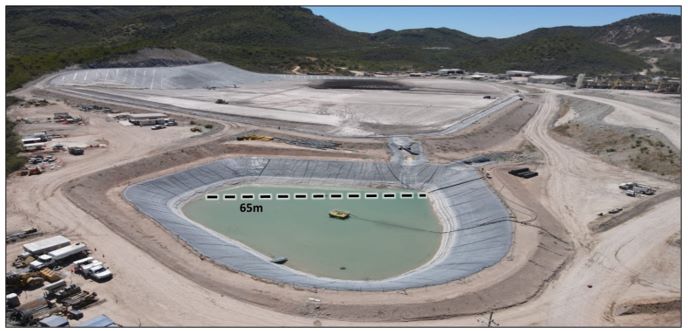
Source: SilverCrest, 2024.
Figure 4‑5: | West Pond |

Source: SilverCrest, 2024.
| |
| Figure 4‑6: | Emergency Pond |
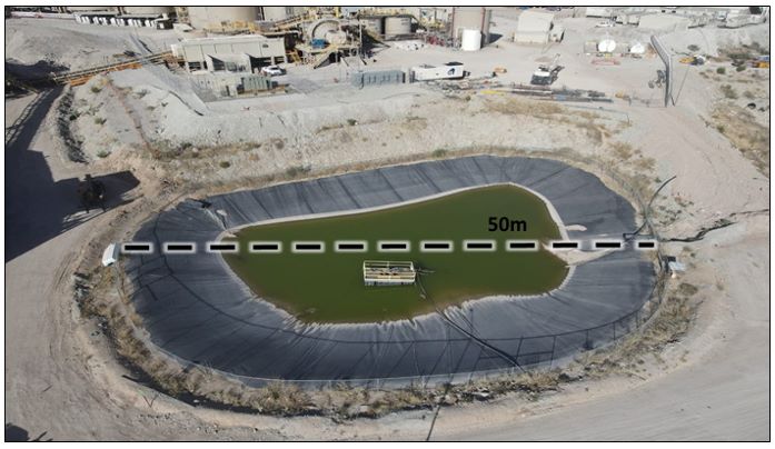
Source: SilverCrest, 2024.
| 4.3.2 | Community Services |
Mining supplies and services are readily available from Cananea and Hermosillo (Mexico), and Tucson (USA). Most of the supplies for Las Chispas Operation are being sourced in Mexico.
| 4.3.3 | Infrastructure |
No surface infrastructure from the historical mining industry remains in the operation area, except for roads and a few eroding rock foundations. Several ranch buildings, corrals, and fencing were acquired from the purchase of ranches.
Information on the infrastructure is discussed in Section 15 of this Report.
Information on the availability of manpower is covered in Section 17.4.2 of this Report.
| 4.3.4 | Power |
Power to the mine site is supplied via a new 54 km 33 KV powerline with an overall capacity of 7.6 MW. The powerline is owned by the Company and connected to the national grid. Comisión Federal de Electricidad (CFE) is the responsible entity for power production and distribution in Mexico.
| |
Emergency gensets have been installed throughout the Property to support critical needs when the grid electrical power is interrupted. Emergency gensets cannot support the entire operations, except in the case of the camp, where an emergency genset has been designed to support continuous operation.
Site access security facility, bridge lighting and the Sonora River pumping station are being serviced by a different powerline.
Additional Information on power requirements is provided in Section 15 of this Report.
| 4.4 | Physiography |
The Las Chispas Operation is located on the western edge of the north-trending Sierra Madre Occidental mountain range, geographically adjacent to the Sonora Valley.
Surface elevations range from 950 to 1,375 masl. The San Gotardo portal to the Las Chispas and William Tell veins is located at 980 masl, the Santa Rosa decline portal to the Babicanora Vein in Area 51 Zone at 1,180 masl, and the Babicanora Central adit portal to the Babicanora Central Zone at 1,170 masl. A third portal to access the Las Chispas veins was completed in May 2023.
Hillsides have steep colluvium slopes or subvertical scarps, which results result from fractures in local volcaniclastic bedrock units.
Rivers and streams generally flow north to south or east to west toward the Sonora River. Flash flooding is common in the area and the Las Chispas Operation has been designed to deal with it.
Vegetation is scarce during the dry season and limited primarily to juvenile and mature mesquite trees and cactus plants. During the wet season, various types of blooming cactus trees and grasses are abundant in drainage areas and on hillsides.
There are no known indigenous communities or protected areas in the vicinity of the Operation.
| 4.5 | Sufficiency of Surface Rights |
There is sufficient surface area for all required facilities, including top soil stockpiles, underground portals, mineralized stockpiles, and waste rock storage facilities (WRSFs), Process Plant, filtered tailings storage facilities (FTSFs), associated infrastructure, and other operational requirements for the planned LOM, as presented later in this Report.
| |
| 5 | HISTORY |
| 5.1 | Regional History |
Historical records indicated mining around the Las Chispas Operation area started as early as the 1640s. Historical records available on mining activities in the 1800s and 1900s are incomplete. There is a gap in mining activity records for Las Chispas between the mid-1930s through to 1974. In 2008, modern exploration activities in the area commenced with Minefinders Corporation Ltd. (Minefinders). The Property was acquired by SilverCrest in 2015 and SilverCrest was acquired by Coeur Mining in 2025.
The history of Las Chispas as summarized in the following sub-sections was extracted from the limited documentation available in the public domain and private libraries. Every reasonable effort has been made to include data for mineralization within the present Property boundaries. However, as the history of the Las Chispas Property area dates back to the 1600s, it was not always possible to determine the precise location of ownership and work completed.
| 5.2 | Property Exploration and Production History |
| 5.2.1 | 1800s and Early 1900s |
Mining interest in the Las Chispas Operation area is considered to have begun in 1640, when outcrop of the Las Chispas Vein was discovered by Spanish General Pedro de Perra (Wallace, 2008), which led to the development of the historical Las Chispas Mine. Through to 1880, small-scale mining, including the excavation of the Babicanora (Central) Adit, was intermittently carried out at this location.
A French company under the name Camou Brothers is reported to have re-developed the Babicanora Mine around 1865 (SilverCrest, 2015). The Babicanora area was mined by Chinese immigrants who originally settled in Baja, relocated to the State of Sinaloa in the late 1800s for agriculture, and were eventually pushed inland by competition from the State of Sonora. Here, they found work in the mines. The Babicanora Adit portal construction and dimensions of underground development were notably different than that of the Las Chispas and William Tell workings. The adit is a 4 m by 4 m drift and 230 m in length developed to intersect the Babicanora Vein.
From 1870s to the 1920s, the Las Chispas Mine was initially operated by the Santa Maria Mining Company, which went bankrupt after the crash of the silver price in 1893 (Russell, 1908). Mr. John (Giovanni) Pedrazzini was given the rights to the Mine and founded the Minas Pedrazzini Gold & Silver Mining Company. From the 1890s to the 1920s, the Pedrazzini family-maintained control of the Las Chispas Mine area together with the Las Chispas, William Tell, Luigi, Varela, and Cumaro veins.
The very limited information available on metal production suggests 200,000 oz of gold and 100 Moz of silver were recovered from mines within the loosely-defined Las Chispas district, including 20 to 40 Moz of silver estimated to have been recovered from the Las Chispas and William Tell veins (Dahlgren, 1883). Wallace (2008) estimates that in the period between 1907 and 1911, annual production at the Las Chispas Mine achieved 22,000 t producing 10,000 oz of gold and 1.5 Moz of silver per year, with an estimated average grade of 1.1 oz per ton gold and 146.8 oz per ton silver (Table 5‑1). Reports indicate that gold and silver were produced from both quartz/amethyst veinlets <5 cm thick and local high-grade shoots up to 4 m thick.
| |
| 1908 | 1909 | 1910 | 1911(1) | Total | |
| Tonnes | 3,286 | 3,064 | 3,540 | 12,000 | 21,890 |
| Gold ounces per tonne | 1.5 | 1.4 | 1.0 | 1.0 | 1.1 |
| Silver ounces per tonne | 199.9 | 187.2 | 136.9 | 125.0 | 146.8 |
| Gold ounces | 4,876 | 4,189 | 3,615 | 12,000 | 24,680 |
| Silver ounces | 656,882 | 573,448 | 484,746 | 1,500,000 | 3,215,076 |
Note: Estimated projected budget for 1911.
Some records suggest that small-scale mining at Espíritu Santo and operation of a small mill at Babicanora occurred in 1935 (Mulchay 1935). Espíritu Santo workings consisted of a small, inclined shaft 80 cm wide, which declined below a small drainage to two short, mineralized drifts. 13.2 tons of mineralized material was reported to have been transported from this small mine in 1934 (Table 5‑2).
| Date | Tons | Ag (oz.) | Au (oz.) |
| Oct. 9, 1934 | 3.3.6 | 75.2 | 0.17 |
| Nov. 21, 1934 | 1.2 | 149.7 | 2.63 |
| Jan. 23, 1935 | 1.8 | 159.3 | 0.66 |
| Jan. 25, 1935 | 2.1 | 490.0 | 1.36 |
| Feb. 22, 1935 | 2.3 | 160.3 | 0.56 |
| Apr. 3, 1935 | 1.2 | 132.3 | 0.44 |
| Total | 1.0 | 131.8 | 0.82 |
Another small mine at La Victoria was in operation around 1940. The workings consisted of three short, mineralized drives on separate levels 30 m in length (Mulchay 1941).
| 5.2.2 | Mid- to Late-1900s to Early-2000s |
Written documented information is not available for the Las Chispas Operation area during this period. Verbal discussions with Luis Pérez, a local operator, indicate that from 1974 to 1984 a small cyanide leach mill was constructed near the highway entrance to the Las Chispas Operation. During this period, 75,000 t of historical waste was processed with doré poured on-site. An estimation of production is not available.
It is assumed that sometime between the mid-1930s and 2008, the historical and 1974 Process Plants were dismantled and transported from the area and both concession and surface ownership likely changed hands at least once in that time.
| |
| 5.2.3 | Minefinders Corporation Ltd. (2008 to 2011) |
| 5.2.3.1 | Overview |
In 2008, Minefinders Corporation Ltd (Minefinders) operating under their Mexican affiliate, Minera Minefinders, acquired concessions within the current Las Chispas Property, but were unable to negotiate with the main district concession owners. Subsequently, Minefinders completed initial exploration work in the district, which they referred to as the Babicanora Project.
Minefinders conducted a systematic exploration program across these concessions between 2008 and 2011. Regional activities consisted of geological mapping and a geochemical sampling program totaling 143 stream sediment and bulk-leach extractable gold (BLEG) samples, 213 underground rock chip samples, and 1,352 surface rock chip samples. The work was successful in identifying three gold targets along a 3 km-long structural zone. The most prospective of these targets was interpreted to be an area between Las Chispas Vein and the Babicanora Vein. Minefinders focused on the western extension of the Babicanora Vein called El Muerto, which is the only part of the trend that was acquired by concession and accessible for exploration work.
Targeted exploration conducted solely within the Babicanora Project area included the collection of 24 stream sediment and BLEG samples, 184 select surface rock chip samples, 474 grid rock chip samples, and completion of seven RC drill holes for a total of 1,842.5 m.
Minefinders Surface Sampling
Turner (2011) describes in detail the work by Minefinders on the Babicanora Project. Outcrop in the area is variable and the sampling was adjusted based on terrain limitations. Minefinders determined that high-grade gold and silver occurrences noted in mine workings and outcrops occurred mainly as discontinuous and narrow quartz stockwork zones. Notable exceptions were a 5 m wide zone and narrow veins in the El Muerto area, northwest of the Babicanora Mine workings.
Twenty-four (24) stream sediment samples were collected from drainages in the Las Chispas Area, as part of a regional sampling program. The large samples were analyzed as 2 kg BLEG samples and via a more conventional analysis of a -80 mesh sieved product. The material utilized for the -80 mesh analysis was obtained after splitting the initial 2 kg used for BLEG analysis. Anomalous zones defined by the regional stream sediment program were later confirmed by a follow-up rock-chip grid sampling program.
All surface rock chip and stream sediment samples were collected by the staff of Minefinders and submitted to ALS Chemex in Hermosillo.
Minefinders Drilling 2011
Minefinders completed a seven-hole RC drill program in 2011. The purpose of the program was to test a porous volcanic agglomerate (i.e., lithic tuff) unit located west of the main mineralization trend in the Babicanora and Las Chispas Areas. The area initially drilled by Minefinders is now known as the El Muerto Zone.
Minefinders contracted Drift Drilling to complete the seven (7) holes utilizing an MPD-1000 RC drill rig. The drilling was completed from existing roads with drill pads enlarged to allow for safe and effective operations. Environmental permitting with the Ministry of Environment and Natural Resources of Mexico (SEMARNAT is the Spanish acronym) was prepared by Bufete Minera y Servicios de Ingeniería S.A. de C.V. and completed on March 23, 2011. All assay work was completed by Bureau Veritas of Hermosillo, Mexico and Reno, Nevada.
| |
The drill program was completed between April 7, 2011, through May 3, 2011, with a total of 1,842.5 m drilled. The drill holes were designed to intercept a range of host rocks in areas of anomalous precious metal contents or adjacent to mine workings. The concept was that bulk tonnage targets might exist within the more porous or chemically reactive rocks. A summary of the drilling is given in Table 5‑3.
| Hole ID | Easting | Northing | Elevation (m) | Dip (°) | Azimuth (°) | Depth (m) | Depth (ft) |
| BAB11-01 | 579,527 | 3,344,033 | 1,135 | -60 | 30 | 304.80 | 1,000 |
| BAB11-02 | 579,526 | 3,344,060 | 1,130 | -90 | 0 | 324.60 | 1,065 |
| BAB11-03 | 579,372 | 3,343,914 | 1,091 | -60 | 50 | 242.30 | 795 |
| BAB11-04 | 579,382 | 3,343,638 | 1,132 | -55 | 60 | 350.50 | 1,150 |
| BAB11-05 | 579,386 | 3,344,130 | 1,053 | -45 | 115 | 198.12 | 650 |
| BAB11-06 | 579,507 | 3,344,503 | 1,009 | -70 | 90 | 182.90 | 600 |
| BAB11-07 | 579,693 | 3,345,216 | 977 | -70 | 90 | 239.30 | 785 |
| Total | 1,842.52 | 6,045 | |||||
The drill results were disappointing in that none of the drill holes intersected the mineralized structure beneath the historical workings. Only narrow zones of gold mineralization at scattered depths were encountered and only one drill hole, BAB11-02, intercepted significant mineralization >900 ppb gold in four narrow intervals. This mineralized interval occurs within basal volcaniclastic sandstones and rhyodacite tuffs cut by propylitic altered dacite dykes.
Results of the drilling indicate that several phases of quartz veining, accompanied by broad zones of argillic and propylitic alteration, are present in the 1.5 km-long target zone. Mineralization was determined to occur as low sulphidation gold-silver epithermal quartz and calcite veins and stockwork within an Oligocene volcanic sequence. This sequence consists of volcaniclastic sedimentary rocks interbedded with rhyolite tuff and andesite dykes/flows cut by dacite dykes.
In 2012, Minefinders dropped their interest in the Babicanora Project.
SilverCrest acquired the Las Chispas Operation in 2015. Their subsequent exploration and drilling activities in the area are summarized in Section 7 of this Report. By acquiring SilverCrest Metals, the entity that holds the rights to the Las Chispas Operation area became a subsidiary to Coeur Mining in February 2025.
| |
| 6 | GEOLOGICAL SETTING, MINERALIZATION AND DEPOSIT |
| 6.1 | Regional Geology |
The Las Chispas Operation is located in northwestern Mexico, where much of the exposed geology can be attributed to the subduction of the Farallon Plate beneath the North American Plate and related magmatic arc volcanism. The east-directed subduction of the Farallon Plate began in the early Jurassic (200 Ma) with tectonic rifting of the supercontinent Pangea (Rogers, 2004). The resulting northwest-trending Sierra Madre Occidental extends >1,200 km from the US-Mexican border to Guadalajara in the southeast.
Delgado-Granados et al. (2000) proposed that subduction of the Farallon Plate occurred at a relatively shallow angle, resulting in continental uplift across northern Mexico and docking of accretionary terranes along the western fringes of the pre-existing Jurassic continental and marine sedimentary rocks and crystalline Cambrian basement rocks.
Volcanism is related to fractional crystallization of mantle-derived basalts during subduction (Johnson, 1991; Wark et al., 1990). The widespread volcanic deposits and intrusive stock development from emplacement of the regional batholith typify the Upper Cretaceous record in the area, which was followed by voluminous accumulation of volcanic flows, pyroclastics, and volcano-sedimentary rocks during the Upper Cretaceous through to the Eocene.
Continental arc volcanism culminated with the Laramide Orogeny in the early to late Eocene (Alaniz-Alvarez and Nieto-Samaniego, A.F., 2007). The waning of compression coincided with east–west-directed extension between late Eocene to the early Oligocene (Wark et al., 1990; Aguirre-Diaz and McDowell 1991; 1993), along the eastern Sierra Madre Occidental flank and is considered the first formation stage of the Basin and Range Province.
By early to mid-Miocene, extension migrated west into Northern Sonora and along the western flank of the Sierra Madre Occidental, resulting in north–northwest to south–southeast trending, west-dipping normal faults. This extensional regime caused major deformation across the Sierra Madre Occidental, resulting in localized exhumation of Precambrian basement rocks within horst structures, especially in the Northern Sierra Madre Occidental (Ferrari et al., 2007). Bimodal volcanic flows capped the volcano–sedimentary deposits of the late Eocene. Migration of later hydrothermal fluids along the pre-existing structures are related to the cooling of the orogenic system.
The Pliocene–Pleistocene is characterized by a general decrease in volcanic activity, with deposition of some basalt flows, and accumulation of conglomerate, locally known as the Baucarit Formation.
Ferrari et al. (2007) summarizes five main igneous deposits of the Sierra Madre Occidental:
| • | Plutonic/volcanic rocks: Late Cretaceous–Paleocene; |
| • | Andesite and lesser dacite–rhyolite: Eocene (Lower Volcanic Complex); |
| • | Felsic dominant and silicic ignimbrites: Early Oligocene and Miocene (Upper Volcanic Complex); |
| • | Basaltic-andesitic flows: late stage of and after ignimbrite pulses; and |
| • | Alkaline basalts and ignimbrites: Late Miocene–Pleistocene (post-subduction volcanism). |
| |
Mineralizing fluids likely originated from mid-Cenozoic intrusions. The structural dilation along the pre-existing faults formed conduits for mineral-bearing solutions. The heat source for the mineralizing fluids was likely the plutonic rocks that commonly crop out in Sonora.
Porphyry deposits of the Sierra Madre Occidental occur in the Lower Volcanic and are correlated with the various Middle Jurassic through to Paleogene age intrusions. Examples of these deposits are Cananea, Nacozari and La Caridad (Ferrari et al., 2007). In Sonora, formation of these deposits is considered to be influenced by east–west and east–northeast to west–southwest directed extension. Early Eocene tectonic activity, which resulted in northwest-trending shear and fault zones, appears to be an important control on mineralization in the Sonora region (Figure 6‑1).
| |
Figure 6‑1: Regional Geology Showing Major Graben of the Rio Sonora and Continuous Normal Fault between Santa Elena and Las Chispas

Source: SilverCrest, 2024.
Note: See text for detailed unit descriptions
| |
| 6.2 | Local Geology |
| 6.2.1 | Lithologies |
The host rocks in the Las Chispas area are generally pyroclastic tuffs and rhyolite-rhyodacite-dacite flows and intercalations cut by rhyolite, trachyandesite and andesite dykes, interpreted to be members of the Lower Volcanic Complex. Locally, hypabyssal and volcanic units observed within underground workings and exploratory drill holes include welded rhyolite-rhyodacite tuff, ashes to lapilli (lithic) tuff, volcano-sedimentary beds, and volcanic agglomerate. A schematic summary of the regional and local stratigraphy is provided in Figure 6‑2.
The volcanic units form a gentle syncline and anticline complex across the Las Chispas Operation, which is cross-cut nearly perpendicular to the fold axis by the dominant vein trend (Mulchay, 1935). A geological map and cross-section looking eastwards through the Las Chispas Operation are shown in Figure 6‑3 and Figure 6‑4.
| |
Figure 6‑2: | Stratigraphic Column for Las Chispas Property |
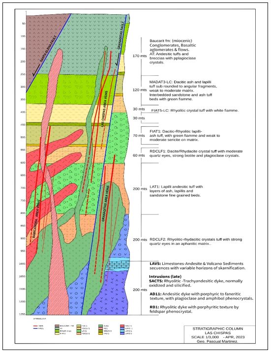
Source: SilverCrest, 2023.
Notes: See text for detailed unit descriptions
| |
| Figure 6‑3: | Las Chispas District Geology Map |

Source: SilverCrest, 2024.
Notes: Refer to Figure 63 for legend. For more details, see Figure 6-9, Figure 7-8 and Figure 7-9.
| |
| Figure 6‑4: | Las Chispas District Cross Section |
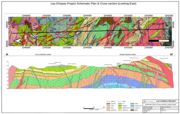
Source: SilverCrest, 2023. Notes: Major mineralization lithologic units for this geology plan map are defined as: LAT1, Lithic andesite tuff and the most significant host for vein-related gold-silver mineralization; RDCLF 1 and 2, rhyodacite flows, which restrict mineralization, but can be mineralized; SACTS, silicic andesite to rhyolite fragments, which occur in sills and dykes, with the dykes associated with mineralization.
| 6.2.2 | Geochemistry |
Thin section and TerraSpec™ hyperspectral studies indicate that the alteration generated during the mineralization events are dominantly multi-pulse neutral and consistent with low-sulfidation mineralization. The alteration assemblage is montmorillonite-illite ± kaolinite ± MgFe chlorite ± pyrite. However, more acidic species of minerals and clays are also present, such as alunite, dickite and ammonium. In conjunction with the more acidic alteration, magmatically derived orthoclase occurs in thin sections as fine-grained interlobate aggregates that occupy the interstices between the coarse-grained quartz. This relationship indicates that the quartz-rich mineralizing fluids and the orthoclase are syngenetic, and therefore part of the same event (Colombo, 2017a). To produce these near neutral clays and minerals in conjunction with the more highly acidic species, two or more distinct fluid pulses are plausible.
A review of the core database was undertaken in January 2018, which included information available from the 46,925 samples of the various mineralization veins that had been sampled to date within the Las Chispas Operation. The review focused on the correlation coefficient (Table 6‑1) and descriptive statistics for modal abundance (Table 6‑2) of the anomalous and expected elements typically associated with low to intermediate sulfidation deposits.
| |
Gold and silver have a strong positive correlation coefficient. Emplacement of both gold and silver appears to be strongly related, although there is thin section evidence of a quartz + gold-only event at Babicanora. The principal low- to intermediate-sulfidation metals of interest (gold, silver, copper, lead, zinc, and antimony) all have a strong affinity for one another. Lead and zinc have a very high positive correlation coefficient of 0.870. However, base metals and accessory minerals typically occur in low abundance within all the mineralized zones.
There is a slight increase in base metal content in the mineralized zones located in the eastern portion of the Las Chispas Operation, such as Granaditas, which is interpreted to be a deeper section of the epithermal system and potentially closer to the source of the mineralizing fluids. This increase may reflect evolution of the fluids as they flowed upwards, and away, or separate base metal-rich pulses, though the mode of emplacement is unclear. Sulfur has a moderately positive correlation with zinc and lead, likely due to sulfur in their respective sulfide minerals. The gold and silver sulfide hosted mineralization in the uppermost portion of the targets has been oxidized and mobilized as sulfate, resulting in reduced contents of total sulfur.
A fluid inclusion study determined that depths of emplacement of mineralization ranged from 100 m to >2 km. The shallow depths of emplacement are outside the current main mineralization zones. Depth of emplacement in the main mineralization zone is well below 1,000 m, with a maximum depth of >2 km (Pérez Segura, 2017). These deeper levels of emplacement are complicated by possible caldera collapse and a change in the paleo-surface.
Evidence for overprinting of low- and high-sulfidation mineralization and alteration with different depths of formation are noted in the fluid inclusion, TerraSpec™ hyperspectral and thin section studies, which point towards caldera collapse as a mechanism of emplacement.
| |
Table 6‑1: Correlation Coefficient Table, Anomalous Values Highlighted, >0.25 and <0.25 (January 2018)
| Au | Ag | Cu | Pb | Zn | As | Ba | Cd | Co | Fe | Hg | Mn | Mo | S | Sb | |
| Au | 1.00 | 0.87 | 0.33 | 0.20 | 0.17 | 0.04 | 0.00 | 0.23 | -0.01 | 0.00 | 0.11 | 0.00 | 0.01 | 0.01 | 0.52 |
| Ag | 0.87 | 1.00 | 0.31 | 0.18 | 0.16 | 0.03 | 0.00 | 0.20 | -0.01 | 0.00 | 0.09 | 0.00 | 0.02 | 0.01 | 0.41 |
| Cu | 0.33 | 0.31 | 1.00 | 0.14 | 0.14 | 0.06 | 0.01 | 0.19 | 0.09 | 0.05 | 0.08 | 0.01 | 0.14 | 0.04 | 0.33 |
| Pb | 0.20 | 0.18 | 0.14 | 1.00 | 0.39 | 0.21 | 0.00 | 0.43 | 0.00 | -0.03 | 0.08 | 0.01 | 0.09 | 0.07 | 0.17 |
| Zn | 0.17 | 0.16 | 0.14 | 0.39 | 1.00 | 0.20 | 0.00 | 0.93 | 0.10 | 0.07 | 0.12 | 0.06 | 0.03 | 0.17 | 0.16 |
| As | 0.04 | 0.03 | 0.06 | 0.21 | 0.20 | 1.00 | 0.00 | 0.20 | 0.07 | 0.07 | 0.11 | 0.08 | 0.06 | 0.18 | 0.12 |
| Ba | 0.00 | 0.00 | 0.01 | 0.00 | 0.00 | 0.00 | 1.00 | 0.00 | -0.01 | -0.01 | 0.04 | 0.39 | 0.02 | -0.07 | 0.21 |
Cd(1) | 0.23 | 0.20 | 0.19 | 0.43 | 0.93 | 0.20 | 0.00 | 1.00 | 0.03 | -0.04 | 0.13 | 0.04 | 0.05 | 0.12 | 0.21 |
| Co | -0.01 | -0.01 | 0.09 | 0.00 | 0.10 | 0.07 | -0.01 | 0.03 | 1.00 | 0.74 | 0.03 | 0.21 | 0.02 | 0.10 | 0.05 |
| Fe | 0.00 | 0.00 | 0.05 | -0.03 | 0.07 | 0.07 | -0.01 | -0.04 | 0.74 | 1.00 | -0.03 | 0.15 | -0.02 | -0.25 | 0.04 |
Hg(1) | 0.11 | 0.09 | 0.08 | 0.08 | 0.12 | 0.11 | 0.04 | 0.13 | 0.03 | -0.03 | 1.00 | 0.02 | 0.03 | 0.05 | 0.14 |
| Mn | 0.00 | 0.00 | 0.01 | 0.01 | 0.06 | 0.08 | 0.39 | 0.04 | 0.21 | 0.15 | 0.02 | 1.00 | -0.02 | -0.03 | 0.31 |
Mo(1) | 0.01 | 0.02 | 0.14 | 0.09 | 0.03 | 0.06 | 0.02 | 0.05 | 0.02 | -0.02 | 0.03 | -0.02 | 1.00 | 0.02 | 0.17 |
| S | 0.01 | 0.01 | 0.04 | 0.07 | 0.17 | 0.18 | -0.07 | 0.12 | 0.10 | -0.25 | 0.05 | -0.03 | 0.02 | 1.00 | 0.00 |
Sb(1) | 0.52 | 0.41 | 0.33 | 0.17 | 0.16 | 0.12 | 0.21 | 0.21 | 0.05 | 0.04 | 0.14 | 0.31 | 0.17 | 0.00 | 1.00 |
Note: (1) Low statistical population.
| |
| Parameter | Count | Minimum | Maximum | Mean | Variance | Standard Deviation | Coefficient of Variation | Skewness | Kurtosis |
| Weight (kg) | 45,944 | 0.22 | 12.94 | 3.899 | 3.77 | 1.942 | 0.5 | 0.81 | -0.23 |
| Length (m) | 46,925 | 0.1 | 7.5 | 1.113 | 0.28 | 0.527 | 0.47 | 0.83 | 0.94 |
| Au (ppm) | 45,934 | 0.001 | 305 | 0.122 | 5.7 | 2.387 | 19.54 | 77.06 | 7,654 |
| Ag (ppm) | 45,934 | 0.2 | 21,858 | 11.068 | 34,356 | 185.353 | 16.75 | 68.64 | 6,237 |
| Cu (ppm) | 29,184 | 1 | 10,250 | 10 | 5,810 | 76 | 7.67 | 91.07 | 11,398 |
| Pb (ppm) | 29,184 | 2 | 8,150 | 37 | 36,473 | 191 | 5.11 | 19.58 | 526.5 |
| Zn (ppm) | 29,060 | 2 | 17,700 | 58 | 45,639 | 214 | 3.65 | 38.92 | 2477 |
| Ba (ppm) | 29,091 | 1 | 10,000 | 151 | 78,966 | 281 | 1.86 | 9.57 | 207.5 |
| Ca (pct) | 28,933 | 0.01 | 25 | 1.086 | 1.87 | 1.366 | 1.26 | 5.69 | 64.74 |
| Cd (ppm) | 3,740 | 0.5 | 130 | 2.023 | 25.96 | 5.095 | 2.52 | 13.74 | 248 |
| Co (ppm) | 24,678 | 1 | 176 | 4 | 31.29 | 6 | 1.37 | 3.45 | 41.09 |
| Hg (ppm) | 4,311 | 0 | 41 | 1 | 1.03 | 1 | 0.93 | 22.57 | 705.3 |
| Mn (ppm) | 29,064 | 1 | 50,000 | 564 | 991,598 | 996 | 1.76 | 26.17 | 1,063 |
| Mo (ppm) | 11,304 | 0 | 1,670 | 4 | 623.7 | 25 | 6.5 | 44.69 | 2,531 |
| S (pct) | 24,815 | 0.01 | 34 | 0.388 | 0.9 | 0.947 | 2.44 | 16.65 | 381.9 |
| B (ppm) | 13,910 | 1 | 1,045 | 5 | 316.2 | 18 | 3.28 | 36 | 1,717 |
| |
| 6.2.3 | Alteration |
All rock types in the Las Chispas Operation show signs of extensive hydrothermal alteration. The thin section and TerraSpec™ hyperspectral studies identified minerals and mineral assemblages consistent with argillic and advanced argillic alteration, including smectite, illite, kaolinite, chlorite, carbonate, iron oxy/hydroxides, probable ammonium, gypsum/anhydrite, silica, and trace alunite.
Generally, most of the mineral deposits drilled to date are above the existing water table; however, paleo-water levels have fluctuated and may have previously been higher. Oxidation of sulfides is observed from near surface to depths >300 m and the presence of secondary minerals is recorded from the Las Chispas underground workings 60 m to 275 m depth below surface. Hematite mineralization occurs as halos around small veins, due to percolated meteoric water along small faults and fractures of oxidized iron sulfides. Strong and pervasive near-surface oxidation is noted to occur in the Babicanora Central Area, where host rocks experienced faulting and advanced weathering to limonite, hematite, and clays.
| 6.2.4 | Mineralization |
Mineralization is interpreted to be a deeply emplaced, low- to intermediate-sulfidation system, with mineralization hosted in hydrothermal veins, stockwork, and breccia. Emplacement of the mineralization is influenced by fractures and low-pressure conduits formed within the rocks during tectonic movements. Mineralization can be controlled lithologically along regional structures, local tension cracks, and faulted bedding planes.
Historical reports and more recent work have investigated the gold, silver, base metals, and gangue minerals associated with the mineralization. The mineralization is 0.10 m to 9.30 m in true thickness and typically encompasses a central quartz ± calcite mineralization corridor with narrow veinlets within the adjacent fault damage zone. Stockwork and breccia zones are centered on structurally controlled hydrothermal conduits.
Historical reporting has identified economic mineralization in the form of silver sulfides and sulfosalts as the primary silver mineral species, and in association with pyrite. Secondary silver enrichment is indicated by the gradation from chlorargyrite near the surface to pyrargyrite at depth.
Silver mineralization dominates throughout the Las Chispas Operation. Ratios of silver to gold using a cut-off grade (“COG”) of 150 g/t silver equivalent (“AgEq”) are approximately: 90:1 at Babicanora Main Vein, 89:1 at Babi Vista Main Vein, 117:1 at Babicanora Norte Main Vein, 56:1 at Babicanora Sur Main Vein, 102:1 at Granaditas Vein, 142:1 at Las Chispas Vein, 172:1 at Giovanni Vein, and 140:1 at William Tell Vein. Overall, a 1:100 gold to silver modal ratio is considered average for the Las Chispas Operation.
Gold mineralization is stronger within the Babicanora Area than within the Las Chispas Area. The modes of gold mineralization currently identified are threefold: 1) gold associated with pyrite and chalcopyrite; 2) gold emplacement with silver sulfides (typically argentite and electrum); and 3) native gold flakes in quartz (Figure 6‑5).
| |
Figure 6‑5: | Thin Section of Gold and Silver Emplacement at Las Chispas |
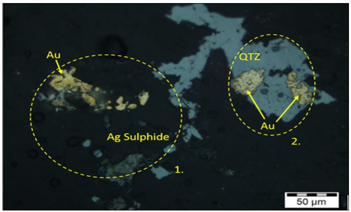
Source: Tetra Tech Canda Inc., 2019.
Additional sulfide species present are minor chalcopyrite, sphalerite and galena. The veins are low in base metal mineralization, except for the far south-eastern extensions of the Babicanora Norte, Babi Vista and Granaditas veins, in the southeastern part of the District. In addition to the petrographic findings in Babicanora, samples of an early sphalerite phase were followed by a later galena phase of mineralization and visual inspection of the base metal mineralization showed galena and sphalerite emplaced at the same time within the same discrete vein. Multiple pulses of base metal-rich fluids of variable composition formed the mineralization at the Las Chispas Operation. There appears to be an increasing base metal content to the southeast and at depth. Government geophysical maps show a large magnetic anomaly to the east of the Las Chispas Operation area, which could be a buried intrusion and potentially the main source of the mineralization in the District.
The veins and stockwork within the Las Chispas Vein consist of fine- to medium-grained, subhedral to euhedral interlocking quartz with minor cavities lined by comb quartz (typically crystals are 5 to 10 mm in length). Quartz-pseudomorphed blades after platy carbonate or other textures that indicate a shallow environment have not been observed. Vein emplacement and form are structurally and lithologically controlled. The rheology of the host rock plays an important role in structural preparation and emplacement of the mineralization. Within the fine-grained welded tuff, veining is narrow, typically with sharp narrow contacts. Veins and breccia emplaced in the more competent, medium-grained lapilli tuffs are wider and commonly occur with parallel splays along the main structure and denser veining in the adjacent fault damaged rocks.
Brecciated mineralization formed in two ways: 1) in zones of low pressure as hydrothermal breccia: and 2) as mechanical breccias.
| |
Mineralization in the hydrothermal breccia is hosted in a siliceous matrix of hydrothermal quartz ± calcite and previously formed vein clasts that have been brecciated and re-cemented (Figure 6‑6). Clasts are typically monolithic, angular, and show minimal signs of milling and rounding by hydrothermal processes. Although heterolithic breccias are present, they tend to be at the intersection points of the cross-cutting faults (striking 360°) to the main trend and at depth. Where breccia clasts are mineralized, mobilization of the clasts within conduits during multi-episodic pulse events is indicated. Gold values increase with increasing amounts of pyrite and chalcopyrite within the quartz matrix.
| Figure 6‑6: | Breccias at Las Chispas |
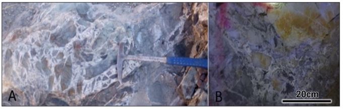
Source: SilverCrest, 2024.
Notes: (A) Hydrothermal angular homolithic breccia, siliceous matrix with calcite and fine-grained sulfides weathering red (rock hammer for scale). (B) Heterolithic breccia with minor rounding of clasts and open space filling. Fine-grained black sulfides and manganese hosted in the crystalline quartz matrix.
Re-cemented mechanical breccia, generated by the reactivation of the fault hosting the mineralization, is also present. These breccias consist of fault gouge, have a cataclasite texture, and are re-cemented with quartz and calcite. This reactivation mechanism also produces open space filling ores, including narrow stockwork quartz ± calcite ± adularia veins. Additional textures present are banding, crustiform, comb, and chalcedonic silica-calcite veins. The matrix commonly has fine disseminated to coarse-grained banded sulfides associated with the cement.
Argentite is the principal silver mineral and occurs in association with galena, pyrite ± marcasite, and chalcopyrite. Gold and silver values have a strong positive correlation with each other and likely precipitated together during crystallization of the quartz. Base metals contents are low in veins. Minor zinc and lead are principally found as blebs and veinlets in black sphalerite and galena. Antimony is minor and arsenic and mercury are conspicuously absent. Minor secondary copper minerals, such as chrysocolla and malachite, occur underground in association with oxidized chalcopyrite, but are rare.
Styles of mineralization present in the Las Chispas Operation include banded veins (Figure 6‑7), stockworks, and quartz-calcite filled hydro-brecciated structures (Figure 6‑8). The presence of epithermal textures, such as bladed calcite (replaced by quartz), miarolitic cavities, and chalcedony/crustiform banding mapped underground, suggest multiple phases of fluid pulses contributed to the formation of the mineral deposits.
Generally, it appears that epithermal mineralization is higher in the system (closer to the paleo-surface) on the northwestern side of the Las Chispas District compared to the southeastern side, where there is an increase in base metal content.
| |
Figure 6‑7: Laminated (Banded) Vein Style Mineralization Along Las Chispas Vein, Tip of Rock Hammer Shown on Upper Left (Near SilverCrest Sample 2277908,1.04 g/t Au and 197 g/t Ag over 1.33 m)
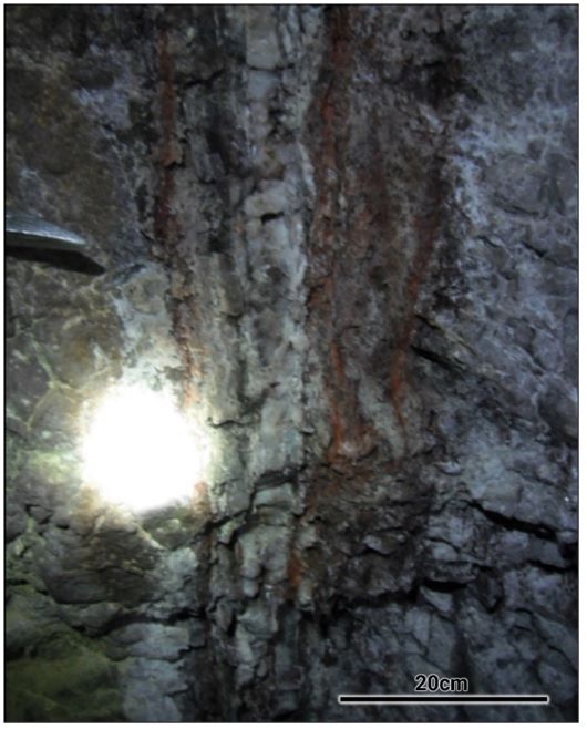
Source: PEA, 2024
| |
Figure 6‑8: Breccia Style Mineralization Along Las Chispas Vein (Base of Las Chispas Gallery near SilverCrest Sample 617179 2.34 g/t Au and 344 g/t Ag)

Source: PEA, 2019. Hammer for scale.
| 6.2.5 | Structural Geology |
Mapping and interpretation of the structural controls on mineralization and post-mineral displacement is presented in Figure 6‑9, Figure 6‑10, and Figure 6‑11. Multiple stages of normal faulting have affected the basin. The main structures are steep, west-dipping (80°) and sub-parallel to the Santa Elena normal fault, which is located along the western margin of the Las Chispas Operation, striking 030°. The area is further cross-cut by younger northwest-trending normal faults that dip to the southwest, creating both regional and local graben structures (Carlos et al., 2010).
| |
| Figure 6‑9: | Overview of the Las Chispas and Babicanora Area Veins |
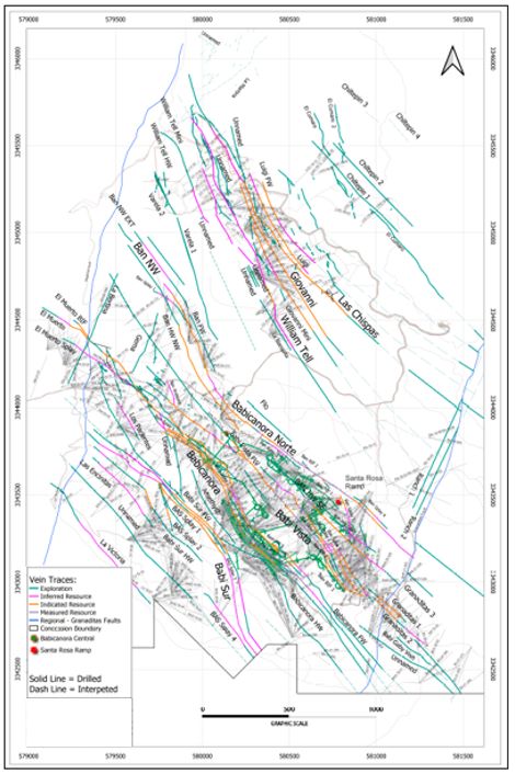
Source: SilverCrest, 2024.
| |
Figure 6‑10: | 3D View of Babicanora Area with Veins |
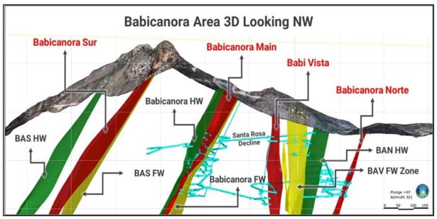
Source: SilverCrest, 2024.
| Figure 6‑11: | High Grade (>500 g/t AgEq) Drill Hole Pierce Points for the Babicanora Veins |
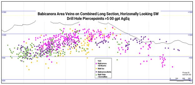
Source: SilverCrest, 2023.
Three major structural corridors have been identified to date in the Las Chispas District and are referred to as the Las Chispas, Babicanora and El Carmen Grabens. All three corridors may be related to horst-and-graben style displacement within broad antiformal-synformal folded stratigraphy, such that the graben structures are bounded by:
| |
| • | Steeply-dipping (80° to 90°) oblique strike-slip sinistral faults trending northeast and south–southwest; and |
| • | Oblique strike-slip dextral faults trending southeast and dipping (60° to 80°) to the northeast. |
Locally, the graben structures are complicated by probable caldera collapse. Circular structures identified in the lineament analysis, in conjunction with locally derived, immature volcanic fill containing sharp primary quartz clasts, indicate local volcanism (Colombo, 2017b). Within a collapsed caldera, telescoping, juxtaposing or overprinting deep mineralization is common. Paleo-surfaces may be down-dropped by 1.0 km, leading to vertical compression of contained mineralized deposits (Sillitoe, 1994).
Current understanding suggests that mineralizing structures are oriented along a northwest–southeast trend. Three structural controls, excluding bedding contacts, are considered to influence alteration and mineralization:
| • | 150° to 170° and are inclined at 65° to 75° to the southwest; |
| • | 340° to 360° and are inclined 75° west to 75° east; and |
| • | 210° to 230° and are inclined 70° to 85° to the northwest. |
High-grade vein mineralization in the District has overall plunge direction of 20° to 30° to the southeast. Figure 6‑7 shows this plunge of high-grade (>500 g/t AgEq) for multiple veins and drill pierce points on a combined longitudinal section for the Babicanora Area.
Locally, the mineralization structures terminate against the northeast-trending regional Las Chispas-Santa Elena Fault, which is a normal fault on the west side of which rocks have down-dropped. Absolute direction and magnitude of movement along the fault in this area is not known. Recent drilling results indicate structural continuity and veining that cuts through this regional fault. At the nearby Santa Elena Mine, drilling indicates that movement along this normal fault postdates mineralization and is west side down by 400 m. This normal fault is also considered to be a major controlling feature for important regional aquifers.
| 6.2.6 | Deposits and Mineral Occurrences |
The Las Chispas District is divided into the Las Chispas Area and the Babicanora Areas. The deposits and veins in each of these areas are described below.
| 6.2.6.1 | Babicanora Main Vein |
The Babicanora Main Vein has a continuous mineralization strike length of 2.2 km with an average estimated thickness of 1.7 m, and includes the Area 51 Zone, Babicanora Central Zone and the El Muerto Zone. The Precious Metal Zone (PMZ) has been drilled continuously to at least 300 m down-dip within the Babicanora Main Vein, and mineralization is exposed on surface to a depth of 500 m. Geological mapping in the Babicanora Area is shown in Figure 6‑12. A June 2022 longitudinal section and cross-section of the Babicanora Area veins are shown in Figure 6‑13 and Figure 6‑14, respectively.
| |
| Figure 6‑12: | Plan View of Geographical Mapping at the Babicanora Area |

Source: SilverCrest, 2024.
| |
| Figure 6‑13: | Babicanora Main Vein Longitudinal Section |

Source: SilverCrest, 2024
| Figure 6‑14: | Vertical Cross Section through Las Chispas Operation Veins, (looking northwest) |
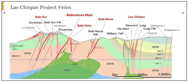
Source: SilverCrest, 2024.
Mineralization is hosted in structurally controlled veins with associated stockwork and breccias. A majority of the high-grade mineralization is located within medium-to coarse-grained lithic tuff (LAT1 unit).
| |
Mineralization is characterized by quartz veins, stockwork and breccias. The mineralization structural zone strikes between 140° to 150° and dips 60° to 70° to the southwest. Several 200° to 220° striking cross- faults and dense fracture sets intersect the Babicanora Main Vein. These intersections appear to influence mineralization by the development of high-grade, steeply southeast-plunging shoots. Observations underground at the nearby Las Chispas Vein indicate that these cross-cutting faults or dense fracture sets can be mineralized for up to 20 m along an approximate 220° strike direction.
Major mineralization host lithological units are defined as:
| • | Lapilli Andesite Tuff (LAT1 unit). The LAT1 unit consists of an andesite lapilli tuff with minor ash and sparse matrix at the top, an intermediate fine sandstone in the middle, and andesite ash and polymictic tuff with abundant fine matrix at the base. The main alteration minerals in this unit are chlorite, hematite in fractures, and weak to pervasive silicification. Argillization is apparent in unit rocks adjacent to faults. The LAT1 unit is 200 m thick, overlies the RDCLF2 unit, and is also cut by trachyandesite and rhyolite dykes at the Babicanora vein area. Due to its stratigraphic position, LAT1 is likely Upper Cretaceous in age and one of the most widely distributed units on the Las Chispas District; |
| • | LAT1 is the best mineralization host unit in the District, due to its lithological composition. Intrusion of the trachyandesite and rhyolite dykes at shallow dips within LAT1 presents suitable structural traps for accumulation of large amounts of gold and silver mineralization. Examples are the Babicanora Main, Babi Vista, Babicanora Norte and Babicanora Sur veins; |
| • | Dacite-Rhyodacite Crystal Tuff (RDCLF1 unit). This unit is mainly a dacite tuff and minor rhyodacite, with abundant biotite, moderate to abundant plagioclase grains, and weak quartz grains in a minor aphanitic, fine-grained matrix. Locally, this unit has moderate to weak fiamme structures and flattened pumice fragments and is widely distributed throughout the Las Chispas District. Generally, this rock is unaltered, but in the areas where cut by rhyolite (RD1) or andesite (AD11) dykes, the rock shows evidence of pervasive alteration and replacement halos of chlorite and carbonates, silicification and oxidation. Being siliceous and moderately competent, outcrops form relatively low topographic relief. This unit concordantly overlies LAT1 and is 60 to 70 m thick. Veins hosted in this geological unit tend to be narrower, due to the competency of the rock. Examples are the upper Babicanora Main, Babicanora Norte NW, and Babicanora Sur veins; |
| • | Rhyolite – Rhyodacite Tuff (RDCLF2 unit). The RDCLF2 unit is a crystalline tuff with abundant quartz, alkali feldspar and plagioclase phenocrysts in an aphanitic matrix, locally with sporadic flattened fiamme structures and pumice fragments. The rock is generally unaltered, except in the areas where it is cut by RD1 and AD11 dykes. There, the rocks show pervasive alteration and replacement halos up to several meters in size. The alteration generally consists of chlorite + pervasive carbonates, silicification and oxidation. RDCLF2 is the oldest outcropping lithological unit in the Las Chispas Operation. However, it overlies the LAVS volcano-sedimentary sequence. This unit is estimated to be 200 m thick and stratigraphic correlation suggests an Upper Cretaceous age. Veins hosted in this geological unit tend to be narrower, due to the tightness of their lithological composition. Examples are the Babicanora Norte Main and Babi Vista Main veins at depth; and |
| • | Trachyandesite-Rhyolite Dykes (SACTS unit). The SACTS unit occurs as strong silicification altered rock with medium-grained phenocrysts of argillized feldspar in an aphanitic matrix. The rock type is mainly trachyandesite, but rhyolite is present locally, likely due to extreme differentiation. In addition to silicification, this rock contains moderately to strongly pervasive hematite, commonly in halos, liesegang rings, and on fracture planes, produced by the leaching of pyrite, consistent with the presence of boxwork textures. The leaching of this pyrite is considered to have contributed to the formation of sulfuric acid in the epithermal fluid system that concentrated the high-grade gold and silver mineralization in the Babicanora area veins. This unit is emplaced oblique to the pseudo-stratification of the enclosing rock, giving the appearance of sills. The dykes vary from 5 to 30 m in thickness, strike NW60° SE, and dip up to 65° to the southeast in the southern portion of the Las Chispas Operation area. On surface, these dykes form relatively high relief features, such as in the Babicanora area. |
| |
General lithologies are andesite to dacite with interbedded rhyolite. These units are crosscut by andesite dykes to the southeast and rhyodacite dykes to the northwest of the Babicanora Main Vein. Strong to intense silicification caps the ridges in the area with a 300 m by 400 m horizontal zone interpreted as possibly sinter (Figure 6‑15 A) that covers the slopes in the northwestern portion of the Las Chispas Operation area.
Mineralization within the Babicanora veins is characterized as a low (northwest portion) to intermediate (southeast portion) sulfidation system. There are numerous sulfidation features, such as sinter capping on the ridges, quartz after calcite bladed textures (Figure 6‑15B), and massive chalcedonic-textured silica (Figure 6‑15C). These high-level features and textures point to the preservation of the mineralization system at depth.
| Figure 6‑15: | A. Sinter Lamina, B. Quartz Replacement of Bladed Calcite with Minor Amethyst, C. Massive Chalcedonic Quartz |
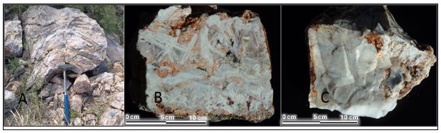
Source: SilverCrest, 2021.
The mineralization of the Babicanora veins has a strong magmatic component. The potassic alteration observed in thin section is crystalline, orthoclase and of magmatic origin. Adularia is also present, but to a more limited extent. Argentite, and acanthite are the principal silver minerals, although electrum and native silver are also present. Gold occurs as native flakes and in association with pyrite and chalcopyrite (Figure 6‑16). Gold and silver values have a strong correlation to each other and likely precipitated together during the crystallization of quartz.
| |
| Figure 6‑16: | Babicanora Thin Section with Gold and Argentite |

Source: SilverCrest, 2017.
Notes:(A) Thin section. A very fine particle of gold is dispersed within the quartz, and it is spatially associated with the argentite. Plane-polarized reflected light. (B) Core, taupe, brecciated fine grained quartz brecciated and recemented with coarse white quartz, fine grained disseminated pyrite throughout.
Gold and silver mineralization can be characterized as three end-member types; 1) breccia hosted; 2) vein hosted; and 3) vuggy quartz hosted (Figure 6‑17 and Figure 6‑18). Contents of base metals are low in the Babicanora area. Zinc and lead are held mainly in green sphalerite and galena.
| Figure 6‑17: | Babicanora Vein Textures |

Source: SilverCrest, 2018.
| |
Figure 6‑18: Drill Hole BA17-51 (Discovery Hole for Area 51 Zone); from 265.9 to 269.2 m, 3.3 m (3.1 m True Thickness) Grading 40.45 g/t Au and 5,375 g/t Ag, with Hematite Breccias, Coarse Banded Argentite, Native Silver, Electrum, and Native Gold.

Source: SilverCrest, 2014.
In June 2019, the Santa Rosa Decline intercepted the Babicanora Main Vein with banded textures and high-grade gold and silver mineralization (Figure 6‑19) within 5 m of the location predicted using a computer-generated resource model based on surface drilling.
| |
| Figure 6‑19: | Babicanora Vein Intercepted by Santa Rosa Decline in June 2019 |
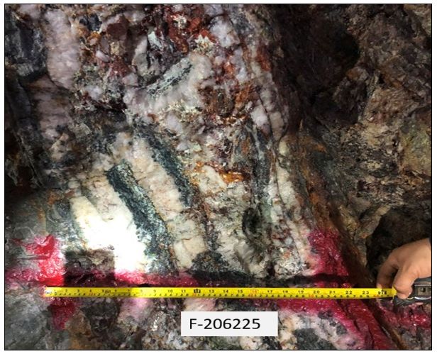
Source: SilverCrest, 2019. Channel sample grading 336 g/t Au and 26,435 g/t Ag.
Following the Babicanora Vein intersection, underground in-vein development proceeded by drifting to the northwest and southeast along the strike of the vein. During drifting, a significant part of the vein appeared to be fractured and faulted and to contain clay material. This material was not logged in core drilling (low recovery intercepts) and sampled for geochemical analysis or metallurgical testing. This fault zone is a prominent, continuous feature within the vein. It ranges in thickness from a few cm up to 2 m and appears to span the entire length of the vein. The fault zone meanders within the vein from the hangingwall to footwall and back (Figure 6‑20 and Figure 6‑21). Post-mineralization relative movement is apparent, but the amount of displacement is unknown.
| |
| Figure 6‑20: | Underground Plan Map of Babicanora Main Vein, Area 51 Zone, Level 1111 (masl) |

Source: SilverCrest, 2024. Fault Zone in Blue.
| |
| Figure 6‑21: | Babicanora Main Vein, Area 51 Zone, Face Map of Vein with Fault Zone (looking northwest) |

Source: SilverCrest, 2024. Fault Zone as White Speckle Texture.
Notes: 1 – quartz breccia adjacent to fault zone; 2 = quartz vein.
The fault zone is oxidized, and contains kaolin clays, limonite, hematite, minor manganese oxides, fine-grained native gold, and the silver halides chlorargyrite and idiorite.
The Babicanora HW and FW veins are sub-parallel to the Babicanora Main Vein. These veins are 5 m to 50 m from the Babicanora Vein and appear to intersect the Babicanora Main Vein near Area 51, potentially causing near-vertical high-grade shoots.
| 6.2.6.2 | Babicanora Norte (Main), HW & FW Veins |
Babicanora Norte Vein has a semi-continuous mineralization strike length of 2 km with an average estimated thickness of 0.65 m. The mineralization is exposed on surface and known to extent to 300 m deep.
The mineralization of the Babicanora Norte veins resembles that at the adjacent Babicanora Main Vein, but without a significant fault zone. A majority of the high-grade mineralization is located within the RDCLF2 (rhyodacite flow) unit, near intersections of cross-cutting 220° striking faults and dense fracture sets. The RDCLF2 unit shows more brittle fracture compared to the LAT1 unit, which has constrained the mineralization vein as a consistently narrower and banded vein compared to Babicanora Main. Argentite and acanthite are the principal silver minerals. Pyrargyrite and polybasite are also present and gold occurs in electrum and native gold flakes in association with pyrite and chalcopyrite (Figure 6‑22).
| |
Figure 6‑22: | Drill Hole BAN18-10, From 93.0 to 95.5 m Grading 61.36 g/t Au and 2,834 g/t Ag with Visible Argentite, Pyrargyrite, Electrum, Native Silver, and Native Gold |
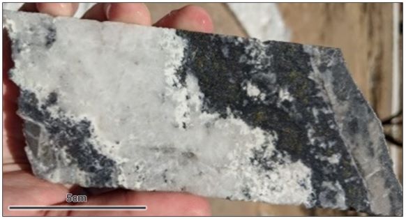
Source: SilverCrest, 2024.
Base metals in Babicanora Norte veins are similar in nature to those described in the Babicanora veins, but the base metal contents are higher (up to 8%). Zinc and lead occur mainly in green sphalerite and galena. A chalky white mineral is immediately adjacent to high-grade silver and may be a silver halide similar to that in the Babicanora Main Vein. Geochemical analyses lack detectable arsenic and mercury. Gold and silver mineralization can be characterized as occurring as three end-member types; 1) breccia hosted, 2) vein hosted, and 3) vuggy quartz hosted.
In February 2020, the Babicanora Norte Vein and Area 200 zone were discovered while completing step-out drilling down-plunge of the high-grade mineralization (Figure 6‑23, Figure 6-24, and Figure 6-25). Drill hole BAN-19-200 intersected 39.27 g/t Au and 3,473 g/t Ag, or 6,595 g/t AgEq (AgEq reported based on 79.51:1 Ag/Au) over 2.5 m downhole length, which includes 79.80 g/t Au and 7,380 g/t Ag, or 13,725 g/t Ag Eq over 0.7 m.
| |
| Figure 6‑23: | Location of Babicanora Norte Vein, Area 200 Zone |

| Figure 6‑24: | Long Section of the Babicanora Norte Vein |

| |
| Figure 6‑25: | Longitudinal Section of the Babicanora Norte Vein Area 200 |

Source: SilverCrest, 2024.
The Babicanora Norte HW, FW, and splay veins are sub-parallel and located 5 m to 30 m from the main vein.
| 6.2.6.3 | Babicanora Sur Vein Area |
The Babicanora Sur Main Vein has a semi-continuous mineralization strike length of 1.5 km, with an average estimated thickness of 1.1 m. Mineralization is exposed on surface and extends to a depth of 600 m. The Precious Metal Zone typical for epithermal veins has an average estimated height of 150 m.
The Babicanora Sur Main Vein is located 300 m southwest of the Babicanora Main Vein and is on a parallel trend. This vein is similar to Babicanora Main, with a fault zone containing clays and associated minerals. The fault zone strikes between 140° to 150°, dips 55° to 65° to the southwest, and is cross-cut by several 220° trending faults and dense fracture sets. Mineralization at Babicanora Sur is hosted in lapilli or lithic tuff and breccia with moderate to strong overprinting alteration (Figure 6‑26). Argentite and acanthite are the principal silver minerals. Gold occurs in electrum and native gold flakes in association with pyrite and chalcopyrite.
As with the Babicanora Main Vein, core loss occurred when drilling the Babicanora Sur Vein and reconciliation while mining may show an impact on grade and thickness.
| |
| Figure 6‑26: | Drill Hole BAS22-209, from 159.00 to 160.45 m at 1.0 m (True Thickness) Grading 38.12 g/t Au and 165.0 g/t Ag |

Source: SilverCrest, 2024.
In Q1 2023, the known extents of the Babicanora Sur Vein were expanded while completing step-out drilling of Inferred Mineral Resources down-plunge of the high-grade mineralization (Figure 6‑27).
The Babicanora Sur HW, FW, and splay veins are sub-parallel and 10 m to 40 m from the Sur Vein and are generally narrower than Babicanora Norte.
Figure 6‑27: | Long Section of the Babicanora Sur Vein |

Source: SilverCrest, 2024.
| |
| 6.2.6.4 | Babi Vista (Main) Vein, HW & FW Veins |
The Babi Vista Vein has a semi-continuous mineralization strike length of 1.9 km with an average estimated thickness of 0.65 m. Babi Vista Vein includes the Granaditas Veins, which have been identified as the faulted continuation of the Babi Vista Main Vein. The structure is exposed on surface and extends to a depth of at least 450 m.
The Babi Vista Vein is located 100 m northeast of the Babicanora Main Vein, on a parallel trend. The vein strikes 140° to 150° and dips 55° to 80° to the southwest. It is cross-cut by several 220° trending faults and dense fracture sets. Mineralization at Babi Vista is hosted in the LAT1 and RDCLF2 units, which show moderate to strong overprinting alteration. Argentite and acanthite are the principal silver minerals. Pyrargyrite, proustite and polybasite are also present. Gold occurs in electrum and as native gold flakes in association with pyrite and chalcopyrite
In Q4 2022, the Babi Vista Vein was expanded to the northwest while completing step-out drilling down-plunge of the high-grade mineralization (Figure 6‑28).
This vein is similar to the Babicanora Norte veins but lacks a significant associated fault zone. The Babi Vista HW, FW, and splay veins are sub-parallel and 10 m to 40 m from the Babi Vista Main Vein.
The southeast faulted continuation of the Babi Vista Vein was historically known as the Granaditas Vein. The Spaniards discovered the Granaditas Mine in 1845 (Dahlgren, 1883) and subsequently mined it. Little information is available on this historical mine. By using an 1882 district map provided by a local rancher additional adits, shafts, and dumps were located in the area. However, the shafts have not been entered due to unstable conditions.
Alteration at the Granaditas vein is consistent with the intermediate sulfidation model, with strong patchy silicification and clay alteration with zones of pervasive sericite and chlorite. Several drill holes have intersected fractured zones and encountered mafic andesite dykes at depth.
Elevated base metals values in the Granaditas drilling suggest that base metals increase to the southeast and may indicate deeper depths of emplacement of the mineralization and proximity to the fluid/heat source.
| |
| Figure 6‑28: | Long Section of the Babi Vista Vein |
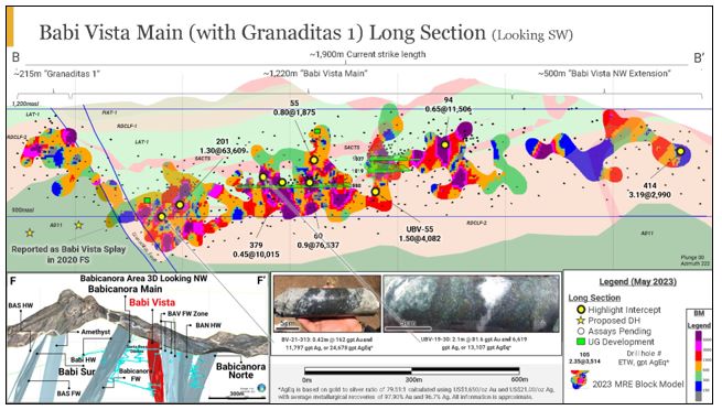
Source: SilverCrest, 2024.
| 6.2.6.5 | Los Parientes |
The Los Parientes Vein is located near the southwest extent of the El Muerto Zone and follows a subparallel trend. This vein is associated with a southeast-directed quartz breccia structure striking 150° and dipping near-vertically. The vein has been mapped on surface for 250 m, is 0.30 m in thickness, and has been sampled from surface chips with grades up to 27.7 g/t Au and 42 g/t Ag. It has been drilled at a spacing of 50 m centers and classified as Inferred Mineral Resources.
| 6.2.6.6 | La Victoria |
La Victoria area is defined by small workings near surface in the south-southwest portion of the Las Chispas Operation. The workings consist of three short and vertically off-set tunnels (La Victoria Mines), 30 m to 60 m in length. These historical workings are in the Santa Elena Regional Fault Zone along with the Nueva Victoria historical working, which is 60 m in length and has two vertical shafts. The vein trends 140° and dips 80° to the northeast. Sampling in the underground workings and on surface suggests that the mineralization in this structure is gold-dominated.
In June 2016, three drill holes were completed down-dip of the workings. Significant mineralization was not intersected, which suggests a possible offset in the mineral continuity at depth or epithermal zonation. Significant alteration was encountered in the drill holes, along with evidence of multiple stages of intrusion. The nature of the mineralization and alteration at La Victoria is currently understood to be late-stage gold remobilization hosted in fractures and fault zones that are closely related to the contacts of the youngest rhyolite dykes.
Additional drilling at La Victoria completed in Q2 2019 and Q4 2022 extended the strike length of the mineralized structure to 530 m and it is currently part of the Inferred Mineral Resources.
| |
| 6.2.6.7 | Encinitas |
Las Encinitas is a quartz vein located to the southwest of Babicanora Sur Main Vein Area. The structure has been identified by drilling and mapping to a strike length of 400 m. The strike direction of Encinitas is 140° azimuth with a 75° dip to the southwest. Mineralization in the area is gold dominant with an average Ag:Au ratio of 8:1.
In H2 2021, a drill program was completed in the area, targeting 400 m of mineralized strike length at 60 to 70 m drill centers. This portion of the Encinitas Vein is included in the Inferred Mineral Resources.
| 6.2.6.8 | Las Chispas Vein |
The Las Chispas Vein has a continuous mineralization strike length of 1.5 km with an average estimated thickness of 3 m. Mineralization is exposed on surface to a depth of 400 m.
The Las Chispas Vein is located in the Las Chispas Area, in the northern portion of the Las Chispas Operation. Historically, the Las Chispas Vein is the most extensively mined vein in the District.
Exploration work to date has focused on defining the lithology, structure, alteration and mineralization, and channel sampling in unmined pillars and surrounding intact vein. Vein mineralization is described as an undulating and dilating quartz stockwork and breccia zone (as defined in underground mapping and in drill core) of 0.10 m to 7.9 m in true thickness, which typically encompasses narrow veins of quartz, visible sulfides, and calcite (Figure 6‑29).
Figure 6‑29: | Drill Hole LC17-45; from 159.6 to 161.9 m at 2.3 m (1.9 m True Thickness) Grading 50.56 g/t Au and 5,019 g/t Ag with Coarse Argentite and Electrum |

Source: SilverCrest, 2014.
| |
The Las Chispas Vein strikes 150° and dips 75° to the southwest. Cross-cutting the Las Chispas Vein are normal secondary faults trending 220° and dipping 65° southeast. These secondary faults appear to have had an important role in generating zones of dilatation for emplacement of the high-grade shoots and breccia zones. Flat to steeply inclined, bedding-parallel faults are also present, associated with drag folds, and offset the late-stage andesite dykes by 10 m to 20 m (Schlische, 1995). A majority of the high-grade mineralization occurs within the lithic tuff units. Geological mapping in the Las Chispas Area and a cross section are shown are shown in Figure 6‑30 and Figure 6‑31, respectively.
Alteration is similar to the other veins at the Las Chispas Operation. Silicification is extensive in mineralization zones. Multiple generations of quartz and chalcedony are commonly accompanied by calcite with minor adularia. Pervasive silicification in vein envelopes is flanked by sericite and clay alteration of the host rock. Intermediate argillic alteration (likely kaolinite–illite–smectite) formed adjacent to some veins. Advanced argillic alteration (kaolinite–alunite) is suspected within the Las Chispas Vein, but confirmation studies of the alteration mineralogy have not been completed. Propylitic alteration dominates at depth and peripherally to the mineralization, with abundant fine-grained chlorite and pyrite proximal to the mineralization. Iron-oxyhydroxides, manganese after pyrite, and other fine-grained sulfides are closely associated with the mineralization. Reactivation of the central fault hosting the mineralization provided a conduit from surface for deep weathering of the sulfides and possible supergene enrichment of the silver mineralization. The andesite dykes are weakly to moderately clay-altered with minor epidote along their narrow chill margins.
Mapping has confirmed that the location and extent of mining represented on historical sections is accurate. From 2017 to 2019, underground rehabilitation, mapping and extensive sampling (>8,000 samples) were completed from the 50 level to the 900 level (850 masl), covering most of the historical workings. Mapping and sampling on all levels is near completion.
In November 2019, the Las Chispas Vein, Area 118 Zone was discovered while completing step-out drilling down-plunge of the high-grade mineralization (Figure 6‑32), based on the intersection in drill hole LC-19-118 of 44.30 g/t Au and 4,551 g/t Ag over an estimated true thickness of 8.6 m. This area occurs just below the current groundwater elevation and has experienced little to no historical mining.
| |
Figure 6‑30: | Plan View of Geological Mapping at the Las Chispas Area |
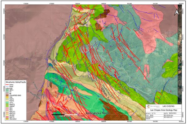
Source: SilverCrest, 2024. Refer to Figure 7-4 for Legend.
| |
| Figure 6‑31: | Geological Cross Section through the Las Chispas Property (looking northwest) |

Source: SilverCrest, 2024.
| Figure 6‑32: | Long Section of Las Chispas Vein with Area 118 Zone |
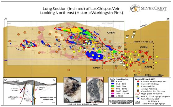
Source: SilverCrest, 2024.
| |
| 6.2.6.9 | William Tell Vein |
The William Tell Vein is located 115 m to the west of, and oriented sub-parallel to, the Las Chispas Vein.
The William Tell vein mineralization is described as a quartz stockwork zone in the footwall of a continuous northeast–southwest fault that strikes 140° and dips 65°. Underground mapping indicates that mining of the main San Gotardo adit terminated against a cross-cutting fault (220°/70°) which, based on drilling results, is interpreted to have 10 m of left-lateral displacement.
The William Tell Vein is hosted in the same sequence of course- to fine-grained volcaniclastic, flows and pyroclastic units that are described for the Las Chispas Vein. Alteration consists of white clays, sericite and fine-grained chlorite with strong silicification. Within the mineralization structure and central vein, fine-grained pyrite, limonite, and iron oxides are present.
Historical mining of the vein is contemporaneous with mining of the Las Chispas Vein, although there is limited historical documentation available. The northern portion of the historical workings can be accessed from the same adit that connects to the San Gotardo level of the Las Chispas Vein. The extents of mapped workings total 3 km horizontally over three levels and 60 m vertically, from 450 level to 650 level. A shaft or a small stope extends from the lower working level. The vertical extent of this shaft/stope cannot be confirmed but based on historical documentation and drilling in the area, it is not considered to be significant.
Mining activity along this structure south of the projected fault cannot be confirmed. However, no open stopes were intersected by drilling where the structure was interpreted to be positioned. Surface workings are not apparent.
In 2016, underground channel sampling completed confirmed high-grade mineralization defined in pillars and intact exposures (Figure 6‑33 and Figure 6‑34).
| |
Figure 6‑33: | William Tell Underground Channel Sample No. 144840 Grading 13.4 g/t Au and 1,560 g/t Ag |

Source: SilverCrest, 2014.
Figure 6‑34: William Tell Vein, Drill Hole LC16-03, from 172 to 176 m, 4 m (1.5 m True Thickness) Grading 2.03 g/t Au and 683 g/t Ag
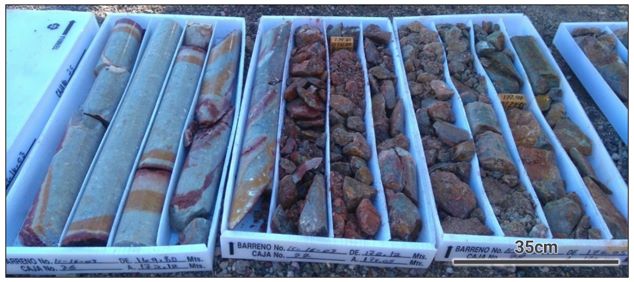
Source: SilverCrest, 2024.
| |
| 6.2.6.10 | Other Structures or Mineral Occurrences of Significance |
Amethyst Vein
The Amethyst (Amatista) Vein is located 200 m southeast of, and parallel to, the Babicanora Main Vein. Historical information is limited, but there are many historical workings, pits and trenches along the 1 km strike length of the structure on surface, which is a lineament.
The lineament structure is steeply dipping and strikes 140°. It is cross-cut by several 200° to 220° trending faults and dense fracture sets that intersect the vein and hosts high-grade mineralization near the intersections. The mineralization is hosted in a sequence of 10° to 15° striking, northeast-dipping lithic tuffs of the LAT1 unit.
Espíritu Santo Vein
The Espíritu Santo workings are developed to the southeast of the Las Chispas and William Tell Veins. Two historical adits and a shaft are accessible and have been mapped and sampled.
Two structural trends appear to have been mined in the workings. The first, on an upper level, strikes 150° and dips 60°. The second structural trend, on the lower level, strikes 290° and dips 48°. The latter mineralization is a stockwork within the footwall that parallels the volcanic bedding contact. At surface, the exposed andesite volcanics are strongly silicified with moderate to strong clay alteration focused along the structural trends. Historical selective underground sampling shows grades at Espíritu Santo to be as high as 500 opt silver (Mulchay, 1941). Historical dump samples returned seven assays with >111 g/t Au and 100 g/t to 892 g/t Ag (Mulchay, 1941). Three drill holes were completed at the target, but with negligible results.
In Q4 2022, seven drill holes were completed in the Espíritu Santo and El Carman veins, to test the extension of the structure near old workings. All drill holes intercepted vein structure but lacked significant gold or silver mineralization.
La Varela Veins
The La Varela workings are located 300 m to the west of the William Tell Vein. Two veins strike 170° and are near vertical with an average thickness of 1 m. Higher grade precious metal mineralization is dominant in the southern part of the two veins. The existing underground workings have been rehabilitated (an estimated 400 m) with mapping and sampling. Three drill holes have been completed in this area. Drill hole LC17-55 intersected 0.8 m grading 2.67 g/t Au and 272 g/t Ag.
Between Q4 2022 and Q1 2023, three drill holes were completed to test the deep extension of the Varela and Los Sheiks veins. Quartz veining was intersected near the targets, but no significant gold or silver mineralization was found.
| |
La Bertina
The La Bertina Vein is located to the northwest of the Babicanora Area and is juxtaposed along the regional normal fault lineament. This vein is associated with a northeast-directed quartz breccia structure with strike between 15° to 20° and dip of 80° to 85°. The vein has been mapped on surface for 300 m with thickness ranging from 0.10 m to
0.15 m and has been sampled from surface chips with grades of up to 0.42 g/t Au and 10 g/t Ag.
0.15 m and has been sampled from surface chips with grades of up to 0.42 g/t Au and 10 g/t Ag.
During Q3 2022, a drill hole targeting the Gema Vein was extended to intersect La Bertina at depth. The vein was intersected, and the best assay result was 9.94 g/t Au and 204 g/t Ag over 1.32 m.
El Cumaro
The El Cumaro Vein is located to the northeast of the Las Chispas Area and is a northwest- directed quartz vein structure that strikes between 330° to 340° azimuth and dips 80°. The vein has been mapped on surface for approximately 600 m. Vein thickness ranges from 0.30 m to 0.50 m and assayed samples have grades up to 3.43 g/t Au and 329 g/t Ag.
Los Chiltepines
The Los Chiltepines Veins are located to the northeast of the Las Chispas Area and are a set of sub-parallel quartz vein structures that strike 155° azimuth and dip 85°. The veins have been mapped on surface for 500 m, are 0.30 m to 0.50 m thick, and assayed surface chip samples grade up to 0.91 g/t Au and 270 g/t Ag.
Ranch Veins
The Ranch Veins are located to east of the Las Chispas area. The Ranch (One) Vein is a quartz vein and quartz breccia structure that strikes southwest and is 0.40 m to 0.50 m thick. The Ranch Dos Vein is located immediately east of, and parallel to the Ranch One Vein and is a quartz breccia structure up to 3.0 m thick. The veins have not been mapped on surface. The veins were discovered in 2018 as part of the infrastructure condemnation program, which led to completion of 16 holes totaling 4,661 m by early 2019. Assay results were low-grade, with several wide intersections of calcite veins and veinlets. The best assay result was for a sample from drill hole RA-18-05 that graded 1.5 g/t Au and 252 g/t Ag over 0.51 m.
In Q4 2022, a drill program testing the northern extension of the Ranch Veins intersected quartz veining with silver and gold mineralization trending in a cross-cutting direction to the previously known structures. The best assay from this structure was sampled from drill hole RA-22-20and graded 3.14 g/t Au and 255 g/t Ag over 0.52 m.
Flo Vein
The Flo Vein is located east of Babicanora Norte and is a southeast-directed quartz vein structure that strikes 220° to 230° and dips 65°. The vein has been mapped on surface for 320 m, is 1.5 m thick, and has been sampled from surface. However, no assays returned values above detection limit.
| |
La Martina
The La Martina Vein is a southwest-directed quartz breccia structure containing massive white quartz located northwest of the Las Chispas Area and developed along a regional normal fault. La Martina Vein strikes 220° to 230° and dips 65° toward the east. The vein has been mapped on surface for 320 m and is up to 1.0 m thick.
Gema Vein
The Gema Vein is a southwest-trending quartz vein structure containing massive white quartz located northeast of El Muerto. The vein strikes 200° to 220° and dips near-vertically. It has been mapped to a length of 230 m and is intersected by multiple north-south secondary veins.
During Q3 2022, 4 drill holes were completed to intersect the main structure veins. Samples of the mineralization returned grades of up to 0.83 g/t Au and 126 g/t Ag over 0.75 m in drill hole GE-22-03.
Limestone and Skarn Target
The limestone and skarn target was developed from drill hole BD-21-01. This drill hole intersected limestone and skarn at an approximate depth of 700 m below surface, and 350 m from the nearest mineralized zone, which is the Babi Vista Main Vein.
Drill hole BD-21-01 targeted the projected depth of the limestone and intersected the unit with strong evidence of skarn development in multiple intercepts at depth. This type of alteration suggests the possibility of favorable conditions for a deep mineralization event within the unit, in the southeast portion of the Property, where it is interpreted that the carbonaceous horizons will be at shallower depths in the footwall block of the Granaditas Fault.
| 6.3 | Deposit Types |
Mineral deposits in the Las Chispas District are classified as low to intermediate sulfidation gold and silver epithermal systems, typical of many deposits in northeastern Sonora, including the nearby Santa Elena Mine (operated by First Majestic Silver Corp.) and the Mercedes Mine (Bear Creek Mining Corporation). Elsewhere in the Sierra Madre, additional examples include the Dolores Mine (Pan American Silver Corp.) and Piños Altos Mine (Agnico Eagle Mines Ltd.) in the State of Chihuahua.
| 6.3.1 | Low Sulfidation Epithermal |
The terms low and intermediate sulfidation are based on the sulfidation state of the sulfide assemblages. Low sulfidation epithermal deposits are formed at shallow depths in hydrothermal systems related to volcanic activity (Figure 6‑35). Low sulfidation deposits typically display all or most of the following characteristics (e.g., Sillitoe 1991; White and Hedenquist 1990):
| • | Hosted in volcanic rocks ranging from andesite to rhyolite in composition; |
| • | Hydrothermal fluids are characterized to be lower temperatures, have near-neutral pH and are reduced; |
| • | Alteration consists of quartz, sericite, illite, kaolin, adularia and silica. Barite and fluorite may also be present; |
| |
| • | Mineralization hosted in quartz and quartz-carbonate veins, veinlets and silicified zones; |
| • | Silica types range from opal through chalcedony to massive quartz. Textures include crustiform and colloform banding, drusy, massive and saccharoidal varieties. Calcite may form coarse blades and is frequently replaced by quartz; |
| • | Deposits of this type may be overlain by barren zones of opaline silica; |
| • | Overall, sulfides typically comprise <5% by volume; |
| • | Sulfides may selectively average up to several per cent in abundance and consist of very fine-grained pyrite, with smaller amounts of sphalerite, galena, tetrahedrite and chalcopyrite; |
| • | Gold may be present as discreet, very fine grains or may be silica or sulfide refractory; |
| • | Gold and silver grades are typically low, but may form high-grade mineralized shoots; and |
| • | Common associated elements are mercury, arsenic, antimony, tellurium, selenium, and molybdenum. |
| |
Figure 6‑35: Detailed Low Sulfidation Deposit with Ore, Gangue and Vein Textures with Estimated Location of Las Chispas Epithermal Mineralization

Source: Buchanan, 1981.
Low sulfidation gold-silver epithermal systems commonly precipitate gold from hydrothermal fluids in near-surface hot spring environments. The mechanism most commonly evoked for gold precipitation is boiling. Boiling occurs as pressure decreases on ascending fluids. The physical and chemical changes that accompany boiling cause breakdown of the gold-bearing chemical complexes and precipitation of the gold. Because pressure from the overlying fluid column or rock column controls the level at which boiling occurs, the location of the boiling zone commonly occurs within a particular vertical depth range. However, this depth can change significantly with changes in the water table, sealing of the system, burial of the system through deposition of volcanic rocks, and emergence due to tectonic uplift. The boiling zone is within 500 m and rarely >1 km below surface at the time of mineralization.
| 6.3.2 | Intermediate Sulfidation Epithermal |
Intermediate sulfidation epithermal systems are less common but share some characteristics of the low and high sulfidation types. Like the high sulfidation types, intermediate types also occur mainly in volcanic sequences of andesite to dacite composition within volcanic arcs.
| |
Like the low sulfidation type, intermediate type mineralization normally occurs in veins, stockworks and breccias. The veins can be rich in quartz, with manganiferous carbonates like manganese-rich calcite or rhodochrosite plus adularia, which hosts the gold mineralization. Gold occurs as native metal, tellurides and in a variety of gold-rich base metal sulfides and sulfosalts. Low-iron sphalerite, tetrahedrite-tennantite and galena commonly are the dominant sulfide minerals. The overall sulfide content of the deposits is in the range of 5% to 20% by volume.
Alteration associated with intermediate type deposits consists of a mixture of high and low sulfidation assemblages that may overprint each other, depending on the evolution of the fluids. Silica (vuggy), advance argillic (alunite, pyrophyllite, diaspore, dickite, and sericite), argillic (kaolinite), anhydrite, barite, sericite, illite, and adularia may be present or absent within the system (Figure 6‑36).
Permeable rocks that host intermediate type deposits may allow the mineral fluids to form a large tonnage of low-grade, bulk-minable stockwork mineralization (Ralf, 2017).

Source: Sillitoe, 2010.
| |
| 7 | EXPLORATION |
| 7.1 | Introduction |
Prior to SilverCrest acquiring the Las Chispas Operation in 2015, no drilling had been completed on the northwest to southeast-oriented Las Chispas and Babicanora mineralization corridors. This trend is 3.5 km long and 3.5 km wide. The work completed by SilverCrest was conducted prior the acquisition by Coeur Mining. Coeur Mining has not completed any work to date on the property. The following is a summary of the work completed by SilverCrest.
Exploration work completed by SilverCrest at the Las Chispas Operation began in March 2016, with the primary focus on the Las Chispas, William Tell, and Babicanora Veins. From March to October 2016, the Phase I exploration program consisted of initial drilling, surface and underground mapping and sampling, and rehabilitating 6 km of underground workings. Twenty-five diamond drill holes totaling 7,105 m were completed during the Phase I program.
From October 2016 to February 2018, the Phase II exploration program consisted of drilling, additional surface and underground mapping and sampling, further rehabilitation of 4 km of underground workings, plus auger and trench sampling of 42 surface historical mineralization dumps. An additional 168 diamond drill holes totaling 40,520 m were completed during the Phase II program.
From February 2018 to February 2019, the Phase III exploration program consisted of drilling, additional surface and underground mapping and sampling, and completing 11 km of underground rehabilitation, the majority of which is located on the Las Chispas Vein in the historical mine. An additional 258 diamond drill holes totalling 76,633 m were completed during the Phase III program.
The continuation of Phase III exploration program (Phase III Extended) from February 2019 to October 2020, consisted of infill drilling to potentially support conversion of Inferred to Indicated Mineral Resources. This phase also included
in-vein development mine face-mapping and chip-channel sampling on the Babicanora Vein in the Area 51 Zone.
The following exploration data and information was collected during this period:
in-vein development mine face-mapping and chip-channel sampling on the Babicanora Vein in the Area 51 Zone.
The following exploration data and information was collected during this period:
| • | Additional core drilling of 1,213 holes totaling 327,124 m; 70% infill and 30% expansion. The cut-off date for drill hole assays was October 16, 2020. Infill drilling provides support for conversion of Inferred to Indicated Mineral Resources; |
| • | Las Chispas Vein underground historical in-vein pillars and historical development for 10 km, with 6,739 chip-channel samples collected for geochemical analysis. Results of this work were used in the Mineral Resource modelling; and |
| • | Survey and mapping of historical workings, Santa Rosa underground decline, and Babicanora (Area 51 Zone) in-vein and waste development. |
| |
From October 2020 to June 2022, the Phase IV exploration program consisted mainly of expansion drilling of known veins, and infill drilling from surface and underground to potentially convert Inferred to Indicated Mineral Resources. Part of the drilling was also designed to test several geological theories with the intention of using that knowledge for the selection of the Mineral Resource modelling parameters; this campaign was called the “Resource and Reserves program”. The Phase IV of exploration drilling totaled 935 (surface and underground) drill holes for 171,787 m. A total of 55,466 core samples were assayed during this phase.
From June 2022 to March 2023, the Phase V exploration program consisted of expansion drilling of known veins for defining Inferred Mineral Resources. Part of the drilling was also designed to complete the Resource and Reserves program, in order to test potential Mineral Resource modelling parameters. Finally, part of the program targeted early-stage exploration targets outside of current Mineral Resources. This program amounted to 541 drill holes totaling 83,707 m. A total of 52,770 core samples were assayed during this phase.
The Phase V Extended exploration program included drilling 154,831 m in 1,358 drill holes. This drilling program targeted conversion drilling in Babicanora Norte, Babicanora Sur, Babi Vista, El Muerto and Encinitas, and with exploration drilling in the La Victoria, Las Chispas Extension, Sorpresa, Ranch-Granaditas, Los Chiltepins, Los Sheiks, and William Tell areas.
From the start of drilling in March 2016 at Las Chispas to October 2024, 4,198 drill core holes totaling 861,709 m were completed with 328,994 drill samples collected and analyzed. Drilling data to October 31, 2024, were used in the Mineral Resource Estimate and in the Mineral Reserve Estimate.
| 7.2 | Underground Exploration at Las Chispas Historical Mine |
Initial access to the underground historical workings, the majority located in the Las Chispas (Historical Vein) Mine, commenced with an underground rehabilitation program in February 2016. Rehabilitation included removal of backfill, construction of a network of bridges and ladders across open stopes, installation of safety cables, removal of obstructions and unsafe overhead supports, construction of new overhead supports, rough rock scaling, and development of a control survey (Figure 7‑1). This work continued until September 2019, when the Company entered a phase of maintenance for all rehabilitation done on the historical underground Las Chispas Mine.
As of the effective date of this Report, 11.0 km of underground work has been rehabilitated. The San Gotardo level continues to be maintained as a main access to underground water supply pumping.
As part of the rehabilitation program, an underground mapping and sampling program began in February 2016. Collection of a series of chip samples was followed by a systematic and continuous saw cut channel sampling program along the rehabilitated underground workings (see the lower left image Figure 7‑1). Samples were collected as transverse samples perpendicular to mineralization and as longitudinal samples taken across the footwall and hangingwall contacts throughout the historical tunnels and stopes. A total of 6,739 chip and channel samples were collected and used for the Mineral Resource modelling, as of the Effective Date of this Report. From these samples, 1,094 assay results graded above a cut-off of 150 g/t AgEq (using an Au:Ag ratio of 1:75), with averages of 4.05 g/t Au and 504 g/t Ag.
| |
| Figure 7‑1: | Photos of Las Chispas Underground Rehabilitation Activities |

Source: Barr et al., 2019.
A total of 94 samples have been collected from historical underground backfill muck at Las Chispas, grading an average 2.1 g/t Au and 256 g/t Ag. These samples and volumes are excluded from the current Mineral Resource Estimate.
Table 7‑1 shows summary statistics of underground chip and channel sampling for the Las Chispas workings, Table 7‑2 and Figure 7‑2 shows other historical underground workings in the Las Chispas Area, and Table 7‑3 shows sample results from the Babicanora Area workings.
| |
| Table 7‑1: | Las Chispas Vein – Significant Channel Sampling Results Before February 2019 |
| Las Chispas | Mean Au | Mean Ag | Mean AgEq(1) |
| 200L | 0.050 | 7 | 11.1 |
| 300L | 1.008 | 141 | 216.6 |
| 350L | 2.329 | 333 | 507.9 |
| 400L | 1.688 | 266 | 392.8 |
| 450L | 3.237 | 440 | 682.6 |
| 500L | 2.549 | 337 | 527.8 |
| 550L | 1.784 | 256 | 389.9 |
| 600L | 0.410 | 57.6 | 88.3 |
| 700L | 0.121 | 15.5 | 24.5 |
| 743L | 0.615 | 118 | 164.3 |
| Average | 0.903 | 131 | 199.17 |
| Number of Samples | 3,923 | 3,923 | 3,923 |
| Maximum Value | 136 | 10,000 | 20,200 |
| Minimum Value | 0.002 | 0.2 | 0.575 |
| Standard Deviation | 3.713 | 444 | 704.0 |
| Number of Samples >150 AgEq | - | - | 805.0 |
Note: (1) AgEq is based on a silver to gold ratio of 75:1, calculated using long-term prices of $1,225/oz gold and of $17.0/oz silver, with average metallurgical recoveries of 95% gold and 90% silver.
| Table 7‑2: | Las Chispas Area, Other Vein Targets – Significant Channel Sampling Results Before February 2019 |
| Las Chispas | Mean Au | Mean Ag | Mean AgEq* |
| El Erick | 1.85 | 118 | 256.4 |
| El Sheik | 1.16 | 75.8 | 162.8 |
| Espíritu Santo | 0.02 | 11.2 | 12.4 |
| Lupena | 0.45 | 39.4 | 73.0 |
| Varela | 0.22 | 26.5 | 43.1 |
| WT500L | 1.05 | 62.8 | 141.4 |
| WT600L | 1.29 | 146 | 242.4 |
| Average | 0.91 | 73.9 | 142.0 |
| Number of Samples | 1,292 | 1,292 | 1,292 |
| Maximum Value | 52.2 | 3,220 | 5,455 |
| Minimum Value | 0.01 | 0.2 | 0.0 |
| Standard Deviation | 3.44 | 221 | 431.1 |
| Number of Samples >150 AgEq | - | - | 237 |
Note: (1) AgEq is based on a silver to gold ratio of 75:1, calculated using long-term gold and silver prices of $1,225/oz gold and $17.0/oz silver, with average metallurgical recoveries of 95% gold and 90% silver.
| |
| Table 7‑3: | Historical Babicanora Main Vein, Other Vein Targets – Significant Channel Sampling Results Before February 2019 |
| Las Chispas | Mean Au | Mean Ag | Mean AgEq(1) |
| Babicanora | 0.41 | 26.1 | 56.6 |
| Babicanora de Abajo | 0.07 | 7.7 | 12.6 |
| Bertina | 0.08 | 4.6 | 10.9 |
| Buena Vista | 0.03 | 7.1 | 9.1 |
| El Muerto | 0.62 | 33.4 | 80.1 |
| Jabali | 0.15 | 10.3 | 21.9 |
| Sementales | 0.49 | 18.7 | 55.0 |
| Average | 0.31 | 16 | 39 |
| Number of Samples | 756 | 756 | 756 |
| Maximum Value | 20.80 | 821 | 2,381 |
| Minimum Value | 0.01 | 0.2 | 1.0 |
| Standard Deviation | 1.22 | 51.9 | 135.8 |
| Number of Samples >150 g/t AgEq | - | - | 52 |
Note: (1) AgEq is based on a silver to gold ratio of 75:1, calculated using long-term prices of $1,225/oz gold and $17.0/oz silver, with average metallurgical recoveries of 95% gold and 90% silver.
| |
| Figure 7‑2: | Las Chispas Historical Longitudinal Section Showing the Mine Workings (looking northeast) |

Source: SilverCrest, 2024. Based on schematic from Pedrazzini circa 1921
| 7.2.1 | Underground Surveying for the Historical Las Chispas Mine |
A network of control points was first established by a Las Chispas Operations surveying crew when access to workings were rehabilitated and secured. Control points were established at 15 m intervals using portable drills, survey chains, distance lasers, and a handheld Brunton compass. The control network was then re-surveyed by third-party contractor, Precision GPS, with a professional surveying crew using a Trimble VX Total Station on level 600 to level 150. The center line of each drift was collected, a dataset of 178 points. The purpose of this survey was to adjust the tape and Brunton compass survey completed previously by Las Chispas Operations staff. This underground control network is the base reference for all underground sampling and drilling activities.
A new 3D topographic survey of the historical Las Chispas workings was carried out in 4 periods between January through October 2024. The work was carried out intermittently due to access restrictions to the areas to be reviewed and limitations in the number of personnel assigned to this task. The campaign was carried out mainly by the Mine Topography team using a BLK 360_LEICA and SR3_Maptek topographic equipment, a Leica total station and an Elios 3 drone, and was verified independently by Unmanned Aerial Services, based in Sudbury, Canada. The survey was guided by old plans and historical information, of which an estimated 70% of the areas were completely resurveyed which the remaining 30% remain inaccessible. A wireframe solid generated from the survey was incorporated into, used to deplete, the mineral resource block model.
| |
| 7.3 | Surface Exploration |
Surface exploration focused on geological mapping and delineation of the numerous historical shafts and portals present at the Las Chispas Operations. As of the effective date of this Report, of 11 km² has been mapped by Las Chispas Exploration geologists. Several historical waste piles were identified near the historical portals. These dumps are referred to as historical stockpiles, following completion of the work described below.
Surface historical stockpile augering, trenching, and sampling surveys were completed. As of the effective date of this Report, assay results have been received for 1,340 historical surface stockpile samples, averaging 1.12 g/t Au and 107 g/t Ag, or 185 AgEq. Select grades from the historical stockpile sampling range up to 4,548 g/t AgEq. The mapping data are georeferenced were used to develop a geographic information system (GIS) database for Las Chispas.
In 2017, historical stockpiles were sampled by a trenching and auger program to collect data, identify stockpiles volumes, and to calculate precious metal grades. Data were collected from field measurements using a global positioning system (GPS) instrument and trenching rock and sediment material in the stockpiles. The stockpiles were subsequently surveyed between December 14, 2017, and January 26, 2018, using a Trimble Spectra Total Station Model TS-415. Samples were sent to ALS Chemex (ALS) in Hermosillo for preparation, and then to the ALS laboratory in North Vancouver for gold and silver analysis.
In total, 41 historical stockpiles at 20 locations within the Las Chispas Operation area were sampled by auger or trenching between July 2017 and January 2018. Table 7‑4 summarizes the stockpiles names and Figure 7‑3 shows their locations.
| |
| Table 7‑4: | List of Surface Historical Stockpiles (Dumps, Muck and Tailing) Mapped in the Las Chispas Operation Area |
| Dump Name | Sample Style |
| North Chispas 1, 2 | Trench |
| La Capilla (LCA), tailings | Auger |
| San Gotardo (LCD)* | Trench |
| Lupena (LUP)* | Trench |
| El Eric | Trench |
| Locarno 1, 2, 3, 4 | Trench |
| Las Chispas 1, 2, 3 (LCH) | Trench |
| La Central | Trench |
| Maria | Trench |
| Chiltepines 1, 2, 3 | Trench |
| La Providenca 1, 2, 3 | Trench |
| Espíritu Santo 1, 2 | Trench |
| La Blanquita 1, 2 | Trench |
| La Curva 1, 2 | Trench |
| La Bertina 1, 2 | Trench |
| El Muerto 1, 2 | Trench |
| Sementales 1, 2 | Trench |
| Buena Vista 1. 2, 3 | Trench |
| Babicanora 1*, 2 | Trench |
| El Cruce 1, 2, 3 | Trench |
| Total | 41 |
| * | Historical stockpiles have been significantly depleted by the Company with processing to date. |
| |
| Figure 7‑3: | Location of Surface Stockpiles and Historical Mine Stockpiles Mapped and Sampled by SilverCrest Phase III Surface Geological Mapping and Lithological Program |
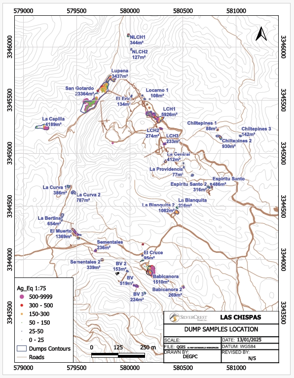
Source: SilverCrest, 2024.
| |
To initially determine the feasibility of evaluating historical stockpiles, an auger program was implemented in July 2017. A standard mechanical gas-powered auger was used to complete the test program. Auger drilling was only found to be useful for one stockpile (La Capilla tailings), due to issues with large rocks and low sample recovery.
The auger program began by setting up north-south oriented base lines near the center of a stockpile. First, a compass, a GPS, and tape were used to mark a hole, then flag and tag it with 10 m between each flag. Depending on the size of the site, a specific number of parallel gridlines were emplaced running east-west and 10 m apart. Second, a tripod was situated over the surface of a flagged hole and a pulley attached at the top. Next, the standard penetration test equipment was aligned at the tripod’s center and the initial hole within 1 m proximity to the flagging. Two personnel manned the sampler with one on the capstan, to drive the sampler through the soil surface and down until either the sampler hits a fixed depth of 1 m or until it could not go any deeper. If a rock prevents downward movement of the auger, it must either drill down by uplifting it or pushing it into the wall, or the piercer can be used to pulverize the rock. When a fixed depth or bedrock is reached, the sampler is pulled up to the surface and the contents placed on a tarp for spreading and homogenization. Each interval was bagged and tagged with the auger hole ID and interval. The process of three personnel manning the sampler and capstan was repeated at 1 m interval depths.
In 2016 and early 2017, initial testing of stockpile material was completed by hand-cut trenches for sample collection. Trenches were hand excavated to 0.5 m in the face of stockpiles with collection of samples every 1 m. The program results indicated that most stockpiles contained significant precious metals to warrant further evaluation.
From mid-2017 to January 2018, mechanical trenching was completed on all accessible historical stockpiles. A backhoe was used to dig trenches 1.5 m deep and pile the excavated material next to the trench for sampling and description. Samples were labelled with an interval ID, GPS coordinate and depth sampled. Sample weights were 3 kg to 5 kg. The backhoe continued to work on an interval until either the soil was reached, or the walls collapsed into the trench. The excavation process continued until the backhoe reached the marked end of the trench. Additionally,
a supervisor analyzed the piles for quartz percentage and historical trash, while describing the grain size and rock type.
Recovery of historical stockpiles for plant feed commenced in April 2022 and continued through until September 2024, during which time an estimated total of 139,900 t grading 1.02 g/t Au, 113 g/t Ag, or 197 g/t AgEq, for 886,240 oz AgEq was mined and processed. The inventory from historical stockpiles has now been fully depleted or deemed uneconomic for recovery.
| 7.3.1 | Surface Mapping |
A comprehensive surface mapping and drill core relogging program was initiated in November 2018 to support development of a detailed stratigraphic section and three-dimensional (“3D”) lithological model across the Babicanora and Las Chispas Areas. The work resulted in an improved understanding of the regional and local structures, location of various intrusive phases, and an understanding of the relationship between host rock lithology and mineralization styles observed in drill core. The resulting 3D model was used to guide exploration targeting in previously overlooked areas and additional discoveries were made during the Phase III program, as follows:
| • | Mineralization footprint expansion of the Babicanora, Babicanora Sur, Babicanora Norte, Babi Vista, Las Chispas and various other minor veins; |
| • | Deep targets under Las Chispas and Babicanora Areas related to specific lithology host rocks, cross-cutting structures, and geochemical zonation; |
| |
| • | Chiltepin Area, northeast of the Las Chispas Area; |
| • | La Victoria Vein mineralization within respect to host lithologies; and |
| • | Mineralization along the Babicanora caldera ring structure and associated rhyolite/andesite dikes. |
Additional surface mapping was completed in Phase V through Q1 2023 to support the targeting for expansion drilling and Inferred Mineral Resources. During this mapping program, the following conclusions were made:
| • | Mineralization footprint expansion along the Babicanora Norte Vein to the northwest; |
| • | Further evidence of a potential deep mineralized zone seen in limestone and skarn units on site; |
| • | Several cross-cutting structures on lesser veins have been discovered including Gema Vein, Martina Vein, and Babi Gaby; and |
| • | Understanding on lithologies and currently known vein systems. |
Mapping continued in the Phase V Extension at scale of 1:500 for target generation and Exploration drillhole planning in the William Tell and Sheiks area, the north-west extension of the Chiltepins-Cumaro structures, along the Ranch-Granaditas fault, and across the La Victoria and La Colorada structures. The mapping supported a reinterpretation of the geology in the footwall of the Granaditas block with LAT occurrence below surface and the presence of a silicified breccia stratabound in the LAT. Drilling programs were successful in delineation of the Ranch-Granaditas veins on the footwall side of the Ranch-Granaditas fault, in addition to intersection of the new La Colorada structure in 3 drill holes, and intersection of the Sheiks structure under and along strike of historical workings.
Geological mapping and lithological modelling on the Las Chispas Operation is illustrated in Figure 7‑4.
| |
| Figure 7‑4: | Geological Mapping and Lithological Modelling at Las Chispas Operations |
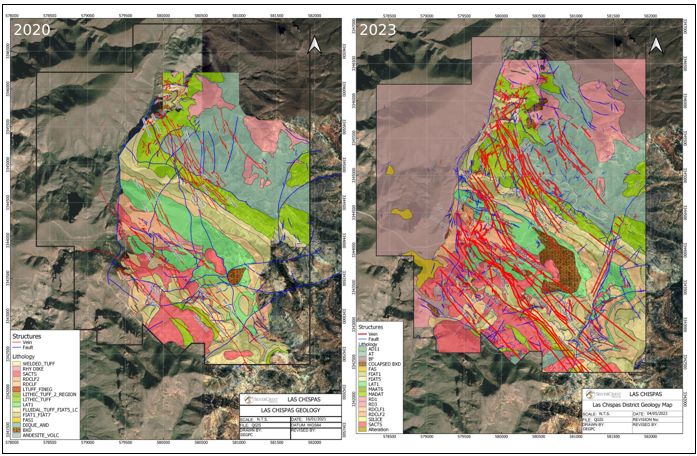
Source: SilverCrest, 2024.
| 7.4 | Underground Channel Sampling in the Babicanora Area |
Underground mining and development are ongoing in the Babicanora Area. Development of the exploration decline began on February 27, 2019, of the main mining production decline and called the “Santa Rosa Decline”. On June 20, 2019, the Babicanora Vein was intersected. In the following days, in-vein development began with surveying, geological mapping, and establishment of sampling protocols. High grades were mapped and sampled on the first day of intersection. From June 20, 2019, to June 30, 2022, 5.2 km of in-vein underground development was completed in all Babicanora Area Veins. From July 2022 to October 2024 10.3 km of additional in-vein underground development was completed in all Babicanora Area Veins. A new portal was established to access the Las Chispas Area in May 2023, along with 1.8 km of ramp development through to December 31, 2024; no new in-vein development has been completed in the Las Chispas Area.
| |
| 7.4.1 | Underground Channel Sample Collection for Grade Control and Mineral Resource Estimation in Babicanora Mine |
This subsection describes Las Chispas Operations procedure for grade control sample collection on the face of in-vein drifting. The procedure consists of the following steps:
| • | Underground continuous channel samples were marked horizontally across the face by a geologist, based on mapping of lithology or mineralization contacts, using spray paint prior to sample collection; |
| • | Sample lengths varied by width of the geological contact and were set to a minimum of 0.30 m in mineralization to a maximum of 1.5 m in waste; |
| • | Two 5 cm deep long cuts separated by 10 cm were made parallel to the sample line using a pneumatic rock saw; then several short cuts perpendicular to the sample line are made at the contacts and between contacts; |
| • | The rock is removed from the channel using a small sledgehammer and hand maul or pneumatic chipper, depending on equipment availability, and placed on a small tarp on the floor; |
| • | The channel is inspected by the geologist for uniform width and depth across the sample, and to verify that the minimum sample mass is 1 kg; |
| • | Samples are collected and placed into clear plastic sample bags with a sample tag, secured with a zip tie, labelled, and stored in a fenced and locked storage facility at the mine prior to being transported by Las Chispas Operations personnel to the SGS laboratory in Arizpe for analysis; |
| • | A single field duplicate is collected from each face, unless determined otherwise by the geologist, from a second channel that is cut within the mineralized zone immediately above and adjacent to the primary sample; and |
| • | Locally, samples were collected along development ribs as longitudinal samples, along backs and overhead stope pillars as transverse samples, and along some crosscuts as transverse samples. The Las Chispas Operations collection program was eventually modified to allow identification of each sample type in the geological database. |
These rib and back samples were used for grade control only and were excluded from Mineral Resource estimation. A total of 23,104 underground channel sample results were collected as of October 2024 (Table 7‑5) (Figure 7-5 to Figure 7-9). In Babicanora Main vein system, 8.4 km of strike length were sampled, with most of it in the Babicanora Main vein. In the Babicanora Norte vein system, 2.7 km of strike length were sampled. In Babi Vista vein system, 4.3 km were sampled. At Las Chispas area, 30 m of new development were sampled.
| |
| Table 7‑5: | Summary of Channel Samples by Vein and Level as of June 30, 2022 |
| Vein | Level | Number of | Number of | Strike Length (m) |
| Channels | Samples | |||
| Babicanora | 945 | 26 | 131 | 89 |
| 961 | 69 | 395 | 226 | |
| 975 | 98 | 500 | 329 | |
| 991 | 86 | 438 | 290 | |
| 1006 | 98 | 499 | 297 | |
| 1021 | 34 | 187 | 125 | |
| 1036 | 75 | 444 | 348 | |
| 1051 | 105 | 711 | 532 | |
| 1066 | 145 | 816 | 525 | |
| 1081 | 141 | 917 | 538 | |
| 1096 | 169 | 1,043 | 641 | |
| 1111 | 151 | 1,038 | 645 | |
| 1126 | 179 | 871 | 655 | |
| 1149 | 176 | 895 | 670 | |
| 1165 | 133 | 757 | 542 | |
| 1185 | 20 | 101 | 76 | |
| Subtotal | 1,705 | 9,743 | 6,528 | |
| Babicanora Hangingwall | 1051 | 18 | 92 | 57 |
| 1066 | 9 | 44 | 35 | |
| Subtotal | 27 | 136 | 92 | |
| Babicanora Footwall | 991 | 3 | 15 | 12 |
| 1006 | 13 | 70 | 48 | |
| 1021 | 25 | 155 | 96 | |
| 1036 | 11 | 59 | 44 | |
| 1051 | 43 | 206 | 98 | |
| 1066 | 38 | 197 | 130 | |
| 1081 | 69 | 381 | 280 | |
| 1096 | 76 | 335 | 295 | |
| 1111 | 88 | 467 | 298 | |
| 1126 | 53 | 269 | 157 | |
| 1149 | 59 | 318 | 205 | |
| 1165 | 11 | 63 | 31 | |
| Subtotal | 489 | 2,535 | 1,694 | |
| Babicanora Central | 1080 | 3 | 18 | 10 |
| 1098 | 17 | 85 | 60 | |
| |
| Vein | Level | Number of | Number of | Strike Length (m) |
| Channels | Samples |
| 1141 | 2 | 15 | 12 | |
| Subtotal | 22 | 118 | 82 | |
| Babicanora Norte | 964 | 73 | 430 | 246 |
| 970 | 30 | 150 | 84 | |
| 988 | 85 | 375 | 266 | |
| 1005 | 54 | 321 | 190 | |
| 1006 | 36 | 156 | 123 | |
| 1024 | 84 | 396 | 242 | |
| 1025 | 48 | 236 | 170 | |
| 1028 | 31 | 163 | 104 | |
| 1040 | 36 | 181 | 122 | |
| 1042 | 41 | 226 | 148 | |
| 1045 | 41 | 219 | 140 | |
| 1060 | 92 | 511 | 365 | |
| 1078 | 57 | 329 | 230 | |
| 1096 | 54 | 283 | 115 | |
| 1115 | 44 | 255 | 158 | |
| Subtotal | 806 | 4,231 | 2,703 | |
| Babicanora Norte HW SE | 997 | 12 | 68 | 38 |
| Subtotal | 12 | 68 | 38 | |
| Babicanora Norte Splay 2 | 1078 | 5 | 28 | 22 |
| Subtotal | 5 | 28 | 22 | |
| Babi Vista | 980 | 110 | 502 | 330 |
| 998 | 38 | 199 | 138 | |
| 1010 | 34 | 183 | 127 | |
| 1016 | 43 | 224 | 154 | |
| 1019 | 40 | 178 | 125 | |
| 1025 | 47 | 230 | 175 | |
| 1031 | 43 | 251 | 158 | |
| 1040 | 53 | 266 | 204 | |
| 1055 | 81 | 370 | 294 | |
| 1073 | 17 | 74 | 63 | |
| 1075 | 52 | 250 | 192 | |
| 1085 | 18 | 97 | 65 | |
| 1091 | 62 | 309 | 236 | |
| 1105 | 10 | 50 | 60 | |
| |
| Vein | Level | Number of | Number of | Strike Length (m) |
| Channels | Samples |
| 1109 | 41 | 209 | 147 | |
| 1130 | 37 | 200 | 142 | |
| 1145 | 17 | 97 | 65 | |
| Subtotal | 743 | 3,689 | 2,675 | |
| Babi Vista Splay | 910 | 3 | 24 | 10 |
| 920 | 83 | 545 | 308 | |
| 940 | 120 | 623 | 446 | |
| 960 | 77 | 431 | 284 | |
| 970 | 19 | 87 | 72 | |
| 975 | 22 | 119 | 103 | |
| 985 | 50 | 264 | 170 | |
| 1000 | 20 | 106 | 70 | |
| Subtotal | 394 | 2,199 | 1,463 | |
| Babi Vista Footwall | 988 | 34 | 166 | 98 |
| 1010 | 26 | 116 | 94 | |
| Subtotal | 60 | 282 | 192 | |
| Giovanni | 1015 | 5 | 38 | 15 |
| Subtotal | 5 | 38 | 15 | |
| Giovanni Mini | 1045 | 8 | 37 | 17 |
| Subtotal | 8 | 37 | 17 | |
| Total | 4,276 | 23,104 | 15,521 | |
| |
| Figure 7‑5: | Long Section of the Babicanora Main vein showing the channel samples descripted in Table 7-5 |

Source: SilverCrest, 2024.
| |
| Figure 7‑6: | Long Section of the Babicanora Norte vein showing the channel samples listed in Table 5-5 |

Source: SilverCrest, 2024
| |
| Figure 7‑7: | Long Section of the Babi Vista vein showing the channel samples descripted in Table 7-5 |
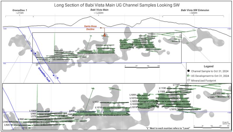
Source: SilverCrest, 2024.
| |
| Figure 7‑8: | Location of Las Chispas District Veins, Santa Rosa Decline and Intersection with Babicanora Main Vein |
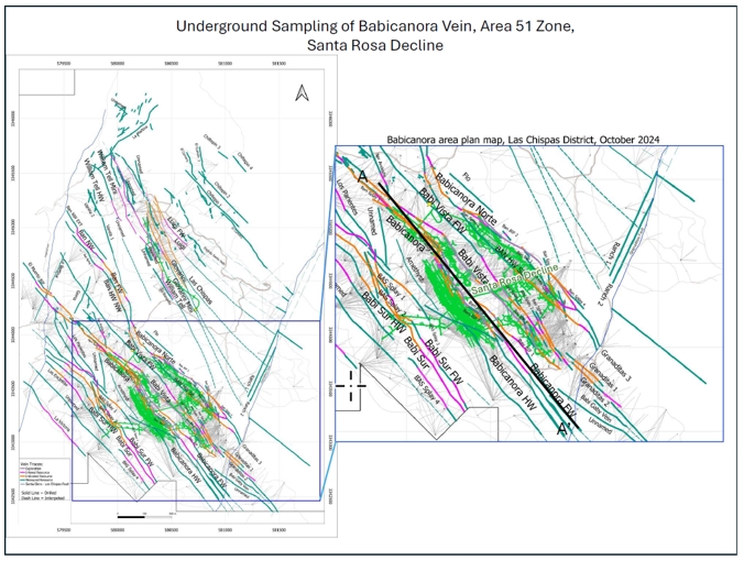
Source: SilverCrest, 2024.
| |
| Figure 7‑9 | Location of Las Chispas District Veins, Santa Rosa Decline and Intersection with Babicanora Main Vein |
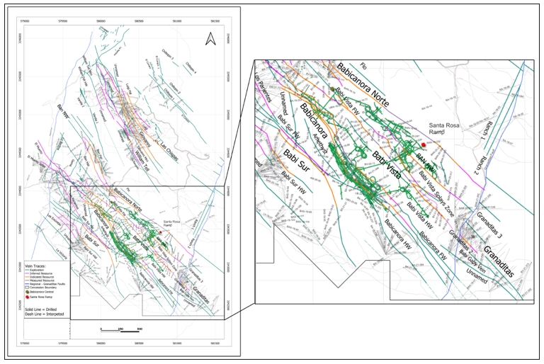
Source: SilverCrest, 2024.
| |
| 7.5 | Aerial Drone Topographic, Underground Exploration and Drill Hole Surveys |
In February 2019, an aerial drone survey to collect light detection and ranging (“LiDAR”) data over the Las Chispas Operation was completed by Precision GPS from Hermosillo, Mexico. The survey used an MD4-1000 drone with a LiDAR module.
During the Phase III and Phase III Extended exploration programs, Precision GPS assisted with surveys of underground decline and drifts in the Babicanora Mine, and drill hole collar surveys up to October 16, 2020. Starting with Phase IV, the on-site operational team has been responsible for surveying all underground development and drill hole collars using a Trimble R12 GNSS.
| 7.6 | Airborne Geophysics |
A helicopter-borne magnetic, spectrometer, and VLF survey was flown over the Las Chispas Property in March 2021, by TerraQuest Ltd. from Markham, Canada. The survey included a total of 2,910 line-km at 50-m line spacing. The information collected from the survey assisted in Property-scale mapping of surface lithology and conductive/resistive geological features.
| 7.7 | Intrusive Age Dating |
In October 2024, 26 drill core and 4 surface rock samples were collected from various intrusive and stratigraphic volcanic phases mapped on the property and were sent to the LaserChron Center at the University of Arizona for U-Pb zircon age dating. Replicate samples were also sent to SGS for whole-rock and trace-element geochemical analysis. The program was intended to identify depositional age ranges for individual intrusive phases and to help establish relationships between intrusive phases from the Babicanora area with those from the Las Chispas area. The results of this program were pending at the end of 2024.
| 7.8 | Drilling |
Program Overview – March 2016 to October 2024
The SilverCrest Phase I and Phase II drilling programs covered the period between March 2016 and February 2018.The Phase III drilling program included drilling up to February 2019. The Phase III Extend ed drilling program, starting in February 2019, focused on in-fill and expansion drilling and was completed on October 16, 2020, with a total of 327,124 m of drilling in 1,213 drill holes. Phase IV, also known as the “Resource and Reserve” or “R&R Drill Program”, included drilling from October 2020 to June 2022 and focused mainly on infill and expansion of known veins with a total of 171,787 m completed in 935 drill holes. Phase V includes drilling from June 2022 to March 2023, which focused on expansion drilling for Inferred Mineral Resources with a total of 83,707 m of drilling in 541 drill holes. Phase V Extended includes drilling from April 2023 to October 2024, with a total of 154,831 m of drilling in 1,358 drill holes (Table 7-6).
From the start of drilling in March 2016 to October 2024, a total of 4,498 drill holes were completed for 861,709 m drilled with 328,994 samples collected for geochemical analysis. Drilling data to October 31, 2024, were used in the Mineral Resource Estimate and in the Mineral Reserve Estimate.
| |
The Phase I drilling program targeted near-surface mineralization, lateral extensions of previously mined areas, and potential deep extensional mineralization proximal to the historical workings. The Phase II drilling program focused on surface drilling at the Las Chispas, Babicanora, William Tell, and Giovanni veins and on underground drilling at the Las Chispas and Babicanora veins. The Phase III drilling program focused on surface drilling at the Babicanora, Babicanora FW, Babicanora HW, Babicanora Norte, Babicanora Sur, Granaditas, Luigi, and Giovanni veins, and on underground drilling at the Las Chispas veins. The Phase III Extended drilling program was an infill program to support potential confidence classification upgrades, and test for expansion of multiple veins.
Phase IV drilling targeted the Babicanora Main, Babicanora Norte, Babicanora Sur, Babi Vista, Encinitas, Amethyst and Las Chispas Vein systems. Phase V focused on expansion drilling along the Babicanora Norte, Babicanora Sur, Ranch, La Victoria, Espíritu Santo, and Babi Vista Vein systems, whereas Phase V Extended focused on conversion drilling in Babicanora Norte, Babicanora Sur, Babi Vista, El Muerto and Encinitas, and with exploration drilling in the La Victoria, Las Chispas Extension, Sorpresa, Ranch-Granaditas, Los Chiltepins, Los Sheiks, and William Tell areas. All these drilling programs and drill hole locations are summarized in Table 7-6.
| Table 7‑6: | Summary of Drilling Meters and Drill Core Sampling Completed to October 31, 2024* |
| Vein | Drill Location | Number of | Length | Number of | Length of |
| Drill Holes | Drilled (m) | Samples | Samples (m) |
| Phase I (March 2016 to October 2016) | |||||
| Las Chispas¹ | Surface | 22 | 6,174.02 | 4,082 | 5,942.51 |
| La Victoria | Surface | 3 | 931.20 | 711 | 924.00 |
| Subtotal | 25 | 7,105.22 | 4,793 | 6,866.51 | |
| Phase II (October 2016 to February 2018) | |||||
| Las Chispas ¹ | Surface | 53 | 13,880.75 | 9,067 | 9,742.70 |
| Underground | 27 | 2,448.50 | 1,699 | 1,679.85 | |
| Babicanora² | Surface | 72 | 22,090.50 | 7,871 | 8,535.25 |
| Underground | 14 | 1,446.70 | 1,252 | 1,415.73 | |
| Granaditas | Surface | 2 | 653.45 | 347 | 383.55 |
| Subtotal | 168 | 40,519.90 | 20,236 | 21,757 | |
| Phase III (February 2018 to September 2018) | |||||
| Las Chispas¹ | Surface | 4 | 1,176.80 | 863 | 940.20 |
| Underground | 13 | 1,708.30 | 1,666 | 1,800.34 | |
| Babicanora | Surface | 25 | 10,967.10 | 2,618 | 2,848.34 |
| Granaditas | Surface | 21 | 6,093.60 | 5,265 | 5,223.63 |
| Babicanora Norte | Surface | 42 | 12,229.40 | 6,362 | 6,695.32 |
| Underground | 2 | 791.20 | 442 | 502.71 | |
| Babicanora Sur | Surface | 7 | 3,069.30 | 933 | 963.46 |
| Ranch | Surface | 9 | 3,141.80 | 1,756 | 1,941.29 |
| Subtotal | 123 | 39,177.50 | 19,905 | 20,915 | |
| Phase III (September 2018 to February 2019) | |||||
| Babicanora² | Surface | 63 | 20,870.40 | 5,641 | 6,044.90 |
| |
| Vein | Drill Location | Number of | Length | Number of | Length of |
| Drill Holes | Drilled (m) | Samples | Samples (m) |
| Underground | 10 | 1,078.60 | 770 | 879.70 | |
| Babicanora Norte | Surface | 16 | 3,464.45 | 2,669 | 3,258.74 |
| Underground | 1 | 356.00 | 293 | 317.11 | |
| Babicanora Sur | Surface | 40 | 10,876.70 | 3,923 | 4,574.15 |
| Ranch | Surface | 5 | 810.00 | 460 | 557.41 |
| Subtotal | 135 | 37,456.15 | 13,756 | 15,632.01 | |
| Phase III Extended (February 2019 to October 2020) | |||||
| Las Chispas¹ | Surface | 163 | 49,377.89 | 17,530 | 15,852.76 |
| Babicanora² | Surface | 241 | 72,175.80 | 20,444 | 19,990.66 |
| Underground | 13 | 2,039.60 | 1,067 | 863.24 | |
| Babicanora Norte | Surface | 276 | 68,281.85 | 17,740 | 15,627.42 |
| Babicanora Sur | Surface | 119 | 35,285.50 | 10,379 | 10,258.73 |
| Babi Vista | Surface | 220 | 69,313.76 | 6,022 | 4,921.80 |
| Underground | 38 | 8,427.70 | 2,898 | 2,636.21 | |
| El Muerto Zone | Surface | 48 | 12,865.65 | 5,038 | 5,218.12 |
| Ranch | Surface | 3 | 708.99 | 196 | 188.41 |
| La Victoria | Surface | 8 | 2,263.30 | 1,542 | 1,613.60 |
| Los Chiltepines | Surface | 16 | 4,638.55 | 2,379 | 2,408.33 |
| DEF Drillholes | Underground | 68 | 1,745.55 | 1,634 | 1,488.41 |
| Subtotal | 1,213 | 327,124.14 | 86,869 | 81,067.69 | |
| Phase IV (October 2020 to June 2022) | |||||
| Babicanora² | Surface | 24 | 7,244.65 | 1,942 | 1,886.64 |
| Underground | 12 | 1,137.20 | 294 | 262.21 | |
| Babicanora Norte | Surface | 53 | 17,615.25 | 5,072 | 5,019.07 |
| Babi Vista | Surface | 216 | 77,362.45 | 19,705 | 18,450.76 |
| Underground | 14 | 2,541.65 | 779 | 778.84 | |
| Babicanora Sur | Surface | 4 | 1,102.80 | 389 | 362.78 |
| El Muerto Zone | Surface | 94 | 31,312.81 | 10,827 | 10,981.04 |
| Granaditas | Surface | 31 | 8,383.55 | 3,433 | 3,208.55 |
| Encinitas | Surface | 8 | 2,486.60 | 1,287 | 1,419.37 |
| Amethyst | Surface | 9 | 4,179.40 | 1,267 | 1,260.58 |
| DEF Drillholes | Underground | 470 | 18,420.87 | 10,471 | 10,289.10 |
| Subtotal | 935 | 171,787.23 | 55,466 | 53,918.94 | |
| Phase V (June 2022 to March 2023) | |||||
| Babicanora² | Surface | 6 | 1,152.29 | 864 | 806.25 |
| Underground | 20 | 4,694.75 | 2,579 | 2,435.95 | |
| |
| Vein | Drill Location | Number of | Length | Number of | Length of |
| Drill Holes | Drilled (m) | Samples | Samples (m) |
| Babicanora Norte | Surface | 66 | 13,922.26 | 8,684 | 8,426.90 |
| Underground | 19 | 2,803.05 | 1,595 | 1,544.00 | |
| Babi Vista | Surface | 23 | 6,377.15 | 3,580 | 3,554.22 |
| Underground | 13 | 2,403.60 | 1,536 | 1,484.52 | |
| Babicanora Sur | Surface | 64 | 22,234.15 | 13,959 | 14,291.44 |
| El Muerto Zone | Surface | 2 | 570.50 | 396 | 409.90 |
| La Victoria | Surface | 7 | 1,384.05 | 1,215 | 1,264.75 |
| Ranch | Surface | 13 | 5,234.55 | 3,791 | 4,122.85 |
| Espiritu Santo | Surface | 8 | 3,404.45 | 3,118 | 3,386.60 |
| Gemas | Surface | 4 | 1,455.35 | 966 | 1,047.65 |
| Las Chispas Extension | Surface | 2 | 1,058.10 | 566 | 597.00 |
| Varelas | Surface | 3 | 1,085.50 | 962 | 1,085.50 |
| DEF Drillholes | Underground | 291 | 15,927.39 | 8,959 | 8,158.71 |
| Subtotal | 541 | 83,707 | 52,770 | 52,616 | |
| Phase V Extended (March 22, 2023 - October 31, 2024) | |||||
| Babicanora Norte | Surface | 21 | 3,183.89 | 2,353 | 2,206.93 |
| Underground | 27 | 6,207.19 | 3,430 | 3,262.75 | |
| Babicanora Sur | Surface | 45 | 14,943.02 | 8,551 | 8,196.29 |
| El Muerto Zone | Surface | 11 | 3,757.45 | 2,318 | 2,290.11 |
| Encinitas | Surface | 9 | 2,325.39 | 1,688 | 1,793.88 |
| West Block | Surface | 1 | 600.40 | 501 | 602.65 |
| William Tell | Surface | 24 | 6,632.59 | 2,261 | 2,084.35 |
| Las Chispas Extension | Surface | 78 | 30,116.69 | 15,430 | 15,171.11 |
| Chiltepines | Surface | 8 | 2,968.35 | 2,179 | 2,337.40 |
| Los Sheiks | Surface | 4 | 1,865.54 | 1,775 | 1,687.70 |
| La Victoria | Surface | 5 | 2,266.99 | 2,267 | 2,258.41 |
| Ranch | Surface | 10 | 5,520.94 | 4,894 | 5,082.63 |
| Babicanora | Underground | 6 | 2,419.94 | 1,647 | 1,798.60 |
| Babi Vista | Underground | 12 | 1,632.15 | 563 | 521.88 |
| DEF Drillholes | Underground | 1097 | 70,390.86 | 25,342 | 16,947.38 |
| Subtotal | - | 1,358 | 154,831 | 75,199 | 66,242 |
| Total | - | 4,498 | 861,709 | 328,994 | 319,016 |
Notes: (1) Las Chispas area totals include some re-drilled holes and holes drilled at Las Chispas, William Tell, Giovanni, Giovanni Mini, La Blanquita, La Varela, Luigi, and other unnamed veins in the Las Chispas area. (2) Babicanora Area totals include holes drilled at Babicanora, Babicanora FW, Babicanora HW, Babicanora Norte, Babicanora Sur, Babi Vista, Amethyst Vein, and other unnamed veins in the Babicanora Area. * 32 Service drill holes and 12 Water well drill holes excluded
| |
Surface collar locations were initially surveyed using a handheld GPS unit, and then professionally surveyed by a local contractor. A survey was completed by external consultant David Chavez Valenzuela in October 2018 and was performed using a GNSS Acnovo GX9 UHF instrument. Up to December 2019 surveys were completed by Precision GPS from Hermosillo, Sonora, Mexico using a Trimble VX10 Total Station and a Trimble R8 GNSS GPS RTK system. The survey provided drill collar locations, information on roads, and additional details on property boundaries. From January 2020 surveys have been conducted by Las Chispas Operations personnel using a Trimble R8 GNSS GPS RTK system.
Underground drill hole collars were surveyed by Precision GPS using the underground control points established for each of the workings. From January 2020 surveys have been conducted by Las Chispas Operations. All drill holes were surveyed downhole as single-shot measurements with a Flex-it® tool starting at 15 m below the collar with measurements at every 50 m to determine deviation. The survey measurements were made to monitor downhole deviations and significant magnetic interference from the drill rods that would prevent accurate readings.
| |
| Figure 7‑10: | Las Chispas Drill Program Phase Map & District Veins |
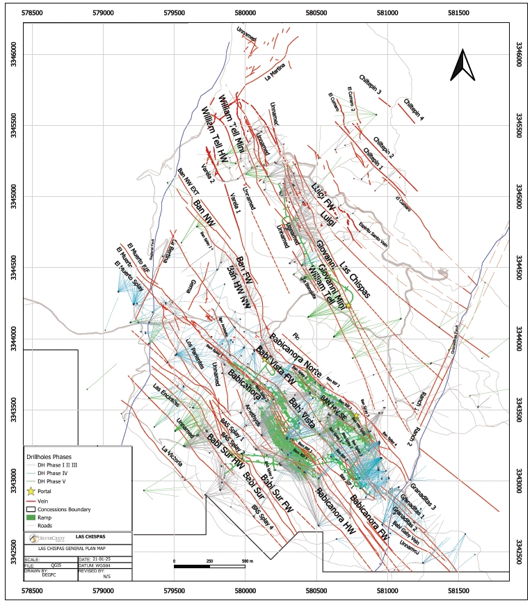
Source: SilverCrest, July 2024.
| |
| 7.8.1 | Drilling Results |
The information in the following sub-sections is summarized from Barr (2016, 2018), and Barr et al. (2019).
Phase 1: March 2016 to October 2016
During the Phase 1 drilling program, 4,793 core samples totaling 6,867 m were collected and assayed. The program targeted the historical Las Chispas Vein to verify the location of the vein and the existence of mineralization along trend of the mapped historical workings. All the drill holes intercepted quartz stockwork veinlets, veining and (or) breccia, and variable amounts of gold and silver mineralization. The results confirmed the presence of the mineralized structure or vein and suggested that relatively unexplored and unmined areas existed proximal to the historical workings.
Additional drilling targeting the William Tell Vein intercepted the mineralized structure or vein in four (4) of seven (7) drill holes.
The 2016 program also included three (3) drill holes (LV16-01, LV16-02, and LV16-03) in the La Victoria Area, located 800 m southwest of the Babicanora Vein, which intersected only low-grade mineralization.
Phase II: October 2016 to February 2018
During the Phase II drilling program, 20,236 core samples totaling 21,757 m were collected and assayed. The program targeted delineation and expansion of known vein targets at the Las Chispas, William Tell, and Babicanora Veins and tested new targets, such as the La Varela, La Blanquita, Granaditas, and Amethyst Veins.
Phase III: February 2018 to February 2019
During the Phase III drilling program, 33661 core samples totaling 36,547 m were collected and assayed. The program targeted delineation and expansion of known vein targets in the Babicanora Area, including the Area 51 Zone, Babicanora HW, Babicanora FW, and Babicanora Sur Veins as well as the newly discovered Babicanora Norte Vein, in addition to the Giovanni Vein in the Las Chispas area. Other newly tested targets for the Phase III program included the Luigi and Ranch Veins in the Las Chispas area.
| 7.8.6.1.1 | Babicanora (Main) Vein |
Delineation and expansion drilling in the Babicanora Area during Phase III focused on the southeast portion of the Babicanora Vein, mainly the area around the high-grade Area 51 Zone. This drilling was accessed via a high-elevation road from the ridge crest permitting drill access to the vein from the hangingwall side. Numerous high-grade intercepts were encountered in this area.
Drilling established strong lithological control on the upper portion of the Area 51 Zone, where welded dacite-rhyodacite crystal tuff (RDCLF) overlies a more permeable lapilli or lithic tuff, which is host to the high-grade mineralization. Mineralization transects the contact; however, it is reduced in both thickness and grade due to permeability contrasts between the lithic and welded tuff units. The orientation of this lithological contact appears to be a controlling feature on the southeast-directed plunge of mineralization within the Babicanora Vein. A lower boundary is less well defined.
| |
| 7.8.6.1.2 | Babicanora Footwall (FW) Vein |
The Babicanora FW Vein is immediately adjacent to the Babicanora Vein and was discovered at the same time as the Babicanora Vein Area 51 Zone, in late-2017. This vein can be observed on surface in select locations and underground in the Babicanora Central adit and Santa Rosa Decline.
| 7.8.6.1.3 | Babicanora Norte Vein |
Surface drilling commenced on the Babicanora Norte Vein in March 2018 and the vein was discovered with the second drill hole, BAN18-02. The vein is located near the portal of the Babicanora Central adit and projects under historical mine stockpiles. Initial drilling was directed 50 m below a shallow shaft where the high-grade vein was intercepted. After discovery, the Babicanora Norte Vein was systematically drilled to the northwest and southeast along strike.
In contrast to the Babicanora Vein, the Babicanora Norte Vein is hosted in welded RDCLF as a discordant extensional vein of consistent width and sharp contacts with host rock. Current interpretation of drilling results has identified a flexure in the Babicanora Norte Vein with change in orientation from 160° azimuth in the northwestern portion to 125° azimuth. This flexure may reflect the presence of a fault, consistent with displacement of local lithologies.
| 7.8.6.1.4 | Babicanora Sur Vein |
The Babicanora Sur Vein is located 300 m southwest and is oriented parallel to the Babicanora Vein. Drilling commenced on Babicanora Sur in the southwest portion of the Las Chispas Operation area, based on availability and access of surface drill rigs on roads constructed in the Babicanora Area.
| 7.8.6.1.5 | Granaditas Vein |
The Granaditas Vein is parallel to the Babicanora and Babicanora Norte veins and consists of similar southeastward-plunging high-grade precious metal mineralization. However, copper, lead and zinc grades increase to the southeast and down-plunge, confirming that the zonation of mineralization originates to the southeast of the Babicanora Area. Drilling during Phase III focused on delineating the high-grade footprint.
| 7.8.6.1.6 | Luigi Vein |
The Luigi Vein was discovered in the footwall of the Las Chispas Vein in mid-2017 but remained unnamed until there was sufficient drilling to delineate a mineralization vein. The Phase III program focused on delineating the vein through underground drilling on the 550 and 600 Level of the historical Las Chispas workings.
| 7.8.6.1.7 | Ranch Veins |
Surface drilling commenced in the Babicanora Ranch area during Phase III, with 13 drill holes planned as condemnation holes in the area surrounding potential processing facilities. Results were low-grade, with several wide intersections of calcite veins and veinlets.
| |
| 7.8.6.1.8 | Espíritu Santo Vein |
The Espíritu Santo historical workings are located to the southeast of the Las Chispas and William Tell Veins. Phase III drilling here targeted two adits and a shaft in this area with three (3) holes being completed. Results were negative and the drilling was considered to be below the potential projected plunge of mineralization.
Phase III Extended: February 2019 to October 2020
| 7.8.6.1.9 | General |
Expansion and in-fill of the Babicanora and Las Chispas Areas during the Phase III Extended program focused on all the main veins (Babicanora, Babicanora FW, Babicanora Norte, Babicanora Sur, Babi Vista and Las Chispas), with adjacent footwall and hangingwall veins and splays to support potential classification upgrades of Mineral Resources.
A systematic drill hole vein piercing pattern of 35 m by 35 m was used to support the conversion of Inferred to Indicated Mineral Resources.
In August 2020, the gold to silver ratio (Ag:Au) used for estimating AgEq was changed from 75:1 to 86.9:1 (see Section 11.1.14), in order to reflect updates in metal prices and metallurgical recoveries.
| 7.8.6.1.10 | Babicanora (Main) Vein |
Drilling on the Babicanora Vein continued to establish lithological controls on the upper and lower precious metal mineralization boundaries, where welded rhyodacite to dacite crystal lithic tuff (RDCLF1 unit, Figure 6‑2) overlies more permeable lapilli or lithic tuff (LAT1 unit), which is the main host to high-grade mineralization. Underlaying the lapilli tuff and establishing the lower boundary is a similar welded unit of rhyodacite tuff (RDCLF2 unit). The downward plunge of the in-vein high-grade mineralization appears to be limited, based on recent drilling that shows vein intersections with low to no grade. These results may indicate the presence of a barren zone to the southeast toward the postulated source of mineralization, typical of epithermal systems (Figure 6‑9).
The Babicanora Vein has a near-parallel hangingwall and footwall vein.
| 7.8.6.1.11 | Babicanora Footwall (FW) Vein |
The Babicanora FW Vein is immediately adjacent to the Babicanora Vein and infill drilling has defined the limits of high-grade mineralization showing several semi-continuous zones or pods. These zones are associated with near-vertical crosscutting structures and shallower southeast plunging in-vein mineralization related to the lapilli tuff host, as observed in association with Babicanora mineralization similar to the adjacent Babicanora Vein.
| 7.8.6.1.12 | Babicanora Norte (Main) Vein |
After discovery in March 2018, the Babicanora Norte Vein was systematically infill-drilled to the northwest and southeast along strike. Infill drilling has defined the limits of high-grade mineralization, showing several semi-continuous zones or pods similar to the nearby Babicanora FW Vein; however, the lithological relationship of mineralization in this vein is within the RDCLF2 unit, which is considered to be a less favorable host. The southeast plunge of high-grade mineralization is still present.
| |
Numerous high-grade in-fill drilling intercepts were made in a newly defined zone, named Area 200 (Figure 6‑9).
The Babicanora Norte Vein has near parallel hangingwall and footwall veins.
| 7.8.6.1.13 | Babicanora Sur (Main) Vein |
The Babi Sur Vein is located 300 m southwest of, and is oriented parallel to, the Babicanora Vein. Infill drilling has defined the limits of high-grade mineralization, showing several semi-continuous zones, or pods, similar to the nearby Babicanora FW Vein.
The Babi Sur Vein has a near-parallel hangingwall and footwall vein (Figure 6‑15).
| 7.8.6.1.14 | Babi Vista (Main) Vein |
The Babi Vista Vein is located 250 m northeast of, and is oriented parallel to, the Babicanora Vein. Drilling commenced on Babi Vista using both underground drilling from access on the Santa Rosa Decline (while developing to the Babicanora Vein), and surface drilling. Discovery and infill drilling defined the limits of high-grade mineralization and showed the presence of several semi-continuous zones, or pods, similar to the nearby Babicanora Norte Vein (Figure 6‑12).
The Babi Vista Vein has a near-parallel footwall vein.
| 7.8.6.1.15 | Babi Vista Vein Splay |
The Babi Vista Vein Splay is located along the southeast strike of the Babi Vista Vein and appears to be a splay off the main Babi Vista Vein. The orientation and zones of mineralization are similar to the Babi Vista Vein. Infill drilling defined the limits of high-grade mineralization and demonstrated the presence of several semi-continuous zones or pods similar to those encountered at the nearby Babicanora Norte Vein.
| 7.8.6.1.16 | Las Chispas Vein |
The Las Chispas Vein is located 1 km northeast of the Babicanora Area and is an area of historical mining activity. The Phase III Extended drilling focused on delineating and in-filling the newly defined Area 118 that had lacked previous mining on the vein. Infill drilling defined the limits of high-grade mineralization and showed that not only is the LAT1 lithology a favorable host, but also that the FIAT unit (fluvial andesite tuff, Figure 6‑2) appears to be a stratigraphically less favorable host (Figure 6‑15).
The Las Chispas Vein has several hangingwall and footwall veins, including the Giovanni, GioMini, Luigi and Luigi FW veins. The Las Chispas Vein is the dominant vein in this area.
Phase IV: October 2020 to June 2022
| 7.8.6.1.17 | General |
During the Phase IV drilling program, 655,466 core samples totaling 53,919 m were collected and assayed. The drill program targeted delineation and expansion of known vein targets in the Babicanora, Babicanora Norte, Babi Vista, and Babicanora Sur veins. Through this drilling several bifurcations and splays were intercepted in multiple vein systems. Newly tested targets in Phase IV included the Las Encinitas Vein.
| |
This phase of drilling also incorporated the underground definition drilling program, which was planned to decrease the drill spacing to 10 to 15 m spaced centers within the Mineral Reserves of the Babicanora Area. The information gained has been used to support both short-range and long-range models.
| 7.8.6.1.18 | Babicanora Main Vein, HW, FW, Splays and Bifurcations |
Drilling in Babicanora Main, including its HW, and FW veins and splays and bifurcations, focused on testing geological theories about the controls on mineralization around high-grade shoots and to re-drill the areas where previous drilling had poor recovery. The information obtained from this program was used to define the Mineral Resource estimation parameters. Further drilling was completed along the lithic (LAT1 unit) and rhyolite (RDCLF1 unit) upper contact, in order to define the controls along the mineralized zone.
The Babicanora Area was targeted by the ongoing definition drilling program. This program was designed to reduce the spacing of the drill hole pierce points from 30 to 35 m to 10 to 15 m centers.
The drill program on El Muerto Zone, located within the Babicanora Vein Area, focused mainly on the infill of Inferred Mineral Resources along the main pods to Indicated Mineral Resources. The drilling also targeted expansion of known veins along strike in the system.
| 7.8.6.1.19 | Babicanora Norte Main Vein, HW, FW, Splays and Bifurcations |
Babicanora Norte Main drilling aimed to prove the extent of the high-grade shoots down-plunge and down-dip, in order to aid definition of the Mineral Resource modelling parameters. Expansion of the Babicanora NW pod along strike to the northwest identified 300 m of previously untested strike length. This phase also targeted the expansion of the Babicanora HW SE vein and infill of the currently identified high-grade shoots to support conversion to Indicated Mineral Resources. The Babicanora Norte HW Splay was identified during this program.
The Babicanora Norte Vein System was targeted during the ongoing definition drilling program. This drilling reduced the drill hole pierce point spacing from 25 to 30 m to 10 to 15 m centers.
| 7.8.6.1.20 | Babi Vista Main Vein, HW, FW, Splays and Bifurcations |
Drilling in the Babi Vista Main vein was completed to support conversion of Inferred to Indicated Mineral Resources around the Babi Vista Splay Zone, which was identified as being part of the Babi Vista Main Vein, and to support expansion along strike and high-grade shoots.
Expansion drilling resulted in the discovery of an additional 500 m of mineralized strike length previously untested to the NW of the structure, which was drilled to Indicated Mineral Resource spacing around high-grade shoots. This area is referred to as the “Babi Vista NW Extension” pod. While testing the extension of this pod to depth, the “Babi Vista Andesite” structure was identified.
A drilling program aiming to test the extension of high-grade shoots inside of previously defined Mineral Resource, in order to support the modelling parameters was conducted in Babi Vista Main Vein.
| |
A zone of sub-parallel veining located on the footwall (north) side of the Babi Vista Main Vein was discovered during the infill-drilling program on the Babi Vista Splay Zone. The area consists of a set of quartz veins, veinlets, and stockwork that splay off the main structure. These splays have been named Babi Vista Splay 1 to 3 and, along with the Babi Vista FW vein, have collectively been labelled as “Babi Vista FW Zone”.
Granaditas drilling tested the extension of the structure to the southeast and infilling of the high-grade material to Indicated Mineral Resources. The Granaditas Vein system was identified as the continuation of the Babi Vista System on the footwall block of the Granaditas Fault.
The Babi Vista System has been targeted by the ongoing definition drilling program. This drilling reduced the spacing of the drill hole pierce points from 25 - 30 m to 10 - 15 m centers in the mineralized zones within the Mineral Reserves, in order to support the mine plan.
| 7.8.6.1.21 | Babicanora Sur Main Vein & Las Encinitas |
During Phase IV, very limited drilling was completed in the Babicanora Sur Main Vein. The drilling of this vein focused on testing the structure near surface around a vein intercept in a drill hole from an earlier phase that was re-interpreted as part of Babicanora Sur.
A drill program targeted the Las Encinitas structure that had been mapped on surface for 200 m of strike length. The vein was drilled at 50 m centers and extended the mineralization for an additional strike length of 400 m.
| 7.8.6.1.22 | Las Chispas Vein |
Drilling in Las Chispas was limited to the remaining program that was planned after the cut-off date for the Phase III of drilling. This plan targeted expansion of the Las Chispas Main and Giovanni veins along strike and to depth.
Phase V: June 2022 to March 2023
| 7.8.6.1.23 | General |
During the Phase V drilling program, 52,770 drill core samples totaling 52,616 m were collected and assayed. The program targeted mainly the expansion along strike and to depth of known veins, with the objective of defining new Inferred Mineral Resources. Newly tested targets from Phase V include the Las Gemas and La Bertina systems.
| 7.8.6.1.24 | Babicanora Main Vein, HW, FW, Splays and Bifurcations |
Drilling in the Babicanora System during Phase V focused on the ongoing definition program being conducted from the underground development. This plan targeted primarily the Babicanora Main Vein and secondarily the Babicanora FW and Babicanora HW veins. This drilling had the objective of reducing the drill hole spacing inside of the Mineral Reserves to an average center spacing of 10 to 15 m, in order to support the mine plan.
Limited drilling from surface targeted the extension of the high-grade shoot near surface in Babicanora Main. Additionally, two drill holes targeted the connection of mineralized pods in the El Muerto Zone.
| |
| 7.8.6.1.25 | Babicanora Norte Vein, HW, FW, Splays and Bifurcations |
The Babicanora Norte Main Vein was targeted for expansion along strike to the northwest and southeast ends. This work included a program to define the newly discovered Babicanora Norte NW Extension to Inferred Mineral Resource spacing. Part of the program was directed to test Babicanora Norte Central and Babicanora Norte SE on trend with open mineralization.
The ongoing definition drilling program continued to work on reducing the drill spacing inside the Mineral Reserves in Babicanora Norte SE and Babicanora Norte HW SE and their splays, with the objective to support the mine plan.
| 7.8.6.1.26 | Babi Vista Main Vein, HW, FW, Splays and Bifurcations |
The surface drill program in Babi Vista targeted infill drilling to inferred spacing on the Babi Vista Andesite vein, and the extension of the open mineralization of shoots along strike, to depth and near surface.
Underground drilling in Babi Vista consisted mainly in the definition drilling program and some exploration drill holes that were planned to provide inputs into the Mineral Resource modelling parameters.
| 7.8.6.1.27 | Babicanora Sur Main Vein |
Phase V drilling in Babicanora Sur Main Vein was planned to expand to the extents of mineralization to depth at the southeast end and to near surface at the northwest end. The program extended the mineralized footprint of the vein by 600 m and was drilled at an average of 50 to 60 m spacing. These portions of the vein are part of the Inferred Mineral Resources.
| 7.8.6.1.28 | La Victoria Vein |
During Phase V, a total of seven drill holes targeted La Victoria Area for testing the extents of the structure mapped on surface. This work resulted in the identification of 550 m of mineralized strike within the structure that remains open on all directions.
| 7.8.6.1.29 | Ranch Area |
From Q4 2022 to Q1 2023, a drill program testing the northeast extension of the Ranch Veins intersected quartz vein mineralization on a cross-cutting trend to the main target. This structure is currently interpreted to be the southeastern extension of Los Chiltepines or Espíritu Santo trends. Mineralization was first discovered on the footwall block of the Granaditas Fault. Since then, veining that could represent the displaced continuity of this mineralization has also been intersected on the hangingwall block too.
This is an open exploration target with potential strike length between 1.5 to 2 km.
| 7.8.6.1.30 | Espíritu Santo Vein |
The Espíritu Santo and El Carman workings were targeted by seven drill holes in Phase V that tested 300 m of strike length around the historical working in the area. Potential continuation of this vein remains open for future testing. Historical documents note the production of multi-kilo ounce grades of silver from the historical mine.
| |
| 7.8.6.1.31 | Gema Vein |
The Gema vein system was targeted by four drill holes that tested 250 m of surface mapped strike length. The program intersected quartz veining, which remains open for future drilling at depth and along strike.
| 7.8.6.1.32 | Las Chispas Vein |
Las Chispas Vein southeast extension was targeted by two exploration drill holes in Q1 2023. The program intersected quartz stockwork on the expected targets with the highest-grade assay containing 0.95 g/t Au and 125 g/t Ag.
| 7.8.6.1.33 | Varela Area |
During Q4 2022, three drill holes tested the deep extension of the Varela and Los Sheiks veins and intersected weak quartz veining. Significant gold or silver mineralization was not found during this program. Channel samples on the historical workings in these veins have shown high-grade gold and silver mineralization, and it continues to be considered a future exploration target for the Company.
Phase V Extended: March 2023 to October 2024
The Phase V Extended program included completion of 1,358 drill holes totaling 154,831 m and a total of 75,199 samples collected for assay analysis (Table 7-6). The Phase V Extended Program included exploration, infill, definition, geotechnical and service drilling in the mineralized vein systems at Babicanora and at Las Chispas.
Infill Conversion Program
| 7.8.6.1.34 | Babicanora Norte |
Drilling in Babicanora Norte vein was completed in two areas to support conversion of Inferred to Indicated Mineral Resources, including the Babi Norte NW Extension zone which occurs 800 m northwest of the Babi Norte Central zone, and the BAN Splay 3 vein which occurs as a hangingwall splay to the Babi Norte Central vein near to existing underground waste development. Drilling of the BAN Splay 3 vein successfully extended the vein both down dip and along strike and linking the Babi HW vein to the Babi Norte Central vein.
| 7.8.6.1.35 | Babi Vista FW |
The Babi Vista FW as part of the Babi Vista FW zone comprise narrow structurally controlled mineralized shoots in the footwall to Babi Main and projecting towards the Babi Norte veins. Infill drilling on the Babi Vista FW vein successfully intersected mineralized veining but was unsuccessful in infilling the high grades previously reported in Inferred resource in the area. Portions of the Inferred vein remain untested for future Infill drilling.
| 7.8.6.1.36 | Babi Sur |
This drilling program focused on infill areas near existing reserves testing the BAS Main and BAS FW veins. New drilling intercepts at 35 m spacing generally confirmed thickness and grade of Inferred resources and expanded the mineralized footprint along mineralized shoots in the central and upper portions of the BAS Main vein. The BAS Deep target remains open and will be drill tested upon completion of a 200 m exploration ramp being completed in the FW to the Babi Sur veins.
| |
| 7.8.6.1.37 | William Tell |
New drilling was completed on the northwestern extent of the previously defined Inferred Resource in William Tell at 35 m drill hole spacing helping to refine the mineralized vein shape and size of William Tell, William Tell HW and William Tell Mini.
| 7.8.6.1.38 | El Muerto |
Drilling in the El Muerto areas focused on conversion of Inferred Resources in the El Muerto Splay vein. Improved confidence in this vein was required to support development costs for accessing other areas in El Muerto mine planning activities. The drilling program successfully intersected mineralized veining at 35 m drill spacing, providing confidence in the area for further consideration in mine planning.
| 7.8.6.1.39 | Encinitas |
The Encinitas vein is located 150 m on the hangingwall side of the Babi Sur vein and was first drill tested in Q2 2021. The infill drilling program completed in 2023 successfully intersected the structure and delineated the mineralized vein shape at 35 m drill hole spacing. The northwestern extent of the vein terminates near the Santa Elena regional fault, where exploration potential for vein continuity exists on the downthrown hangingwall side of the fault.
Exploration Program
| 7.8.6.1.40 | La Victoria and La Colorada |
Exploration drilling conducted at La Victoria aimed to test mineralization to the southeast and down plunge from the existing Inferred Resource in 3 holes. These holes successfully intersected the La Victoria vein with low mineral concentration. Intersections of a new wide low grade gold structure occurred in the up-hole direction, on the hangingwall side of La Victoria. The new mineralized structure, called La Colorada, remains open as an exploration target both along strike and dip. Additionally, the northwestern extent of La Victoria vein terminates near the Santa Elana regional fault, where exploration potential for vein continuity exists on the downthrown hangingwall side of the fault.
| 7.8.6.1.41 | Las Chispas Extension |
The Las Chispas Extension drilling program continued from the Phase V drilling program and tested the southeastern extension of the Las Chispas Area veins following intersection of a blind vein that was intersected in the new Las Chispas Ramp in Q2 2023 230 m southeast of the edge of drill tested mineralization in the in Las Chispas Area. The drilling program intersected several additional vein and stockwork systems, and successfully defined the Las Chispas Extension and La Portal vein trending along 150° azimuth, and intersections with the Sorpresa and Sorpresa Splay veins trending on 130° azimuth.
In the northwest, mineralization in the Las Chispas area is hosted in younger volcanic rocks of the MADAT, FIAT 1 and FIAT 5. Following the southeast extension along plunge of mineralization, the mineralization becomes hosted in older volcanic rocks of the RDCLF 1, LAT and RDCLF2 which is similar to the mineralization in the Babicanora area. This program presents several opportunities for exploration targets within the older volcanic rock sequence underneath the northwestern Las Chispas area, and to fill gaps in drilling information that exist between the Babicanora and Las Chispas areas.
| |
| 7.8.6.1.42 | Ranch-Granaditas |
The Ranch-Granaditas vein target is located in the footwall of the Granaditas-Ranch fault system approximately 1.6 km north of the Granaditas deposits. Known fault movement of 150-200 m vertically within the Granaditas-Ranch fault results in upward relative offset in the footwall block as evidenced from stratigraphy and from the offset seen between the Babi Vista Main vein in continuity with the Granaditas veins. The Ranch-Granaditas exploration program successfully intersected two veins with mineralization hosted within northerly dipping LAT and RDCLF2 volcanic units. These veins show textural, alteration, mineralogical and geochemical characteristics that correspond mainly to the deep zone of a low sulfidation epithermal system, showing low to moderate anomalies of Pb, Zn and Cu and is interpreted to be the southeasterly continuation of the Chiltepins structure, uplift with the footwall to the Granaditas-Ranch fault.
| 7.8.6.1.43 | Los Chiltepins and Cumaro |
Previously drilling in the Los Chiltepin targeted mineralization in the younger volcanic host rocks of the MADAT, FIAT 1 and FIAT 5. A broad drilling campaign was initiated in Q4 2024 to test these veins to the northwest and southeast of previous drilling, in addition to test mineral potential within the older RDCLF 1, LAT and RDCLF 2 volcanic units. The drilling campaign was in progress at the end of December 2024.
| 7.8.6.1.44 | Los Sheiks |
Los Sheiks was first tested by drilling in Q4 2022. Resampling of historical development in the area, 100 m in length on one level, returned assay values up to 40.90 g/t Au. Local surface mapping at scale of 1:500 in addition to remapping of the historical workings completed in 2024 outlined several mineral controlling structures including thin stockwork veinlets with 150° strike and 75 to 80° inclined to the southwest mostly and a mineralized fault with 150° strike and 80° inclined to the northeast. Exploration drilling commenced in Q4 2024 to test projected structural intersections down plunge from mineralization trends mapping in the historical workings and from surface mapping. Drilling was ongoing in this area at the end of December 2024.
| |
| 8 | SAMPLE PREPARATION, ANALYSIS AND SECURITY |
Coeur Mining has not completed any exploration or sampling on the Las Chispas Property. The following is a summary of the sample preparation, analyses and security as implemented by SilverCrest at Las Chispas Operations.
To date, four types of sample collection programs have been conducted at the Las Chispas Operation:
| • | Underground and surface sampling as chip samples and (or) channel samples; |
| • | Stockpile/backfill sampling as intact muck from historic draw points and (or) placed or remobilized muck within underground development; |
| • | Drill core sampling as hand-split core or wet saw-cut core; and |
| • | Surface stockpile trenching and sampling. |
The sample collection approaches completed on the Property are described in the following subsections. A sample processing facility was established where core samples were logged, bulk density measurements collected, drill core photographed, sampled, bagged and tagged, and stored on-site prior to being transported to the laboratory by Las Chispas Operations staff. Underground chip samples were bagged and tagged at the point of collection and also stored at the sample processing facility. All coarse reject materials and pulps were stored in a covered building.
| 8.1 | Underground Chip Sample Collection Approach (up to December 2021) |
This subsection describes the approach to underground rock sample collection for historical underground workings and newly developed in-vein drifting, which consisted of the following steps:
| • | Underground continuous chip and channel samples were marked by a geologist, per lithology or mineralization contacts, using spray paint prior to sample collection; |
| • | Samples were collected using a small sledgehammer, a hand maul and chisel, and a small tarp on the floor to collect the chips, or a power saw for channelling; |
| • | Samples were collected and placed into clear plastic sample bags with a sample tab, secured with a zip tie, labelled, and stored in the semi-secure core storage facility at Las Chispas prior to being transported to ALS Chemex Hermosillo or the Bureau Veritas Minerals Laboratories (Bureau Veritas), also located in Hermosillo; |
| • | Samples were collected along development ribs as longitudinal samples, along backs and overhead stope pillars as transverse samples, and along some crosscuts as transverse samples. The collection program was eventually modified to allow identification of each sample type in the geological database; |
| • | For the historical workings, a follow-up program was initiated to collect duplicate and new samples using a power saw to cut a channel along the initial chip path. Saw-cut samples were collected at every five to eight samples, depending on access; |
| • | Each sample path was labelled with a sample number written on a piece of flagging tape, which was anchored to the development wall; and |
| |
| • | Las Chispas Operations senior geologist and exploration manager conducted a follow-up review of the sampling program to ensure that all development drifts near the mineralization zone were sampled, that transverse samples were properly collected across veins, and that the samples were clearly and properly labeled. |
| 8.2 | Underground Muck/Stockpile Sample Collection Approach (up to December 2021) |
Underground muck and (or) stockpile sample collection steps consisted of:
| • | Samples were collected at random within the existing historic muck and material stockpiles in the Las Chispas, William Tell, and Babicanora workings; |
| • | The average mass of the samples collected was 4 kg; |
| • | Sample spacing along continuous muck piles was 10 m, suggesting that each sample could represent 20 t to 40 t of material, depending on the size of the pile; |
| • | Sample collection was completed by hand or shovel, from near surface material, as non-selective collection to represent both the fine and coarse fragment portions of the muck piles; |
| • | The muck samples were then collected and placed into clear plastic sample bags with a sample tab, secured with a zip tie, labelled, and stored in the semi-secure core storage facility at Las Chispas prior to being transported to ALS Chemex, Hermosillo; and |
| • | Las Chispas Operations senior geologist and Vice President of Exploration and Technical Services conducted a follow-up review of the sampling program to ensure all appropriate muck piles were sampled and the samples clearly and properly labelled. |
| 8.3 | Drill Core Sample Collection Approach |
This subsection describes the approach taken to drill core sample collection, which consisted of the following steps:
| • | Project geologists logged the drill holes, and the senior geologist reviewed the logs; |
| • | For a newly discovered vein, the first 10 drill holes were completely sampled. Additional drill holes could be entirely sampled, if such sampling was needed to establish an understanding of geology and mineralization; |
| • | Sample intervals were laid out for mineralization, veining, and structure. 10 m before and after each mineralization zone was included in the sampling intervals. A minimum of 0.5 m sample lengths of mineralized material was taken up to a maximum of 3 m in non-mineralization rock; |
| • | Each sample interval was either split using a hand splitter or cut using a wet core saw, perpendicular to veining, where possible, to leave representative core in the box and to reduce any potential bias in the sampled mineralization submitted with the sample; |
| • | Half of the core was placed into clear plastic sample bags with a sample tab, secured with a zip tie, labelled, and stored in the semi-secure core storage facility at Las Chispas before being transported to ALS Chemex Hermosillo; and |
| |
| • | A follow-up review of the core sampling program, to ensure that each sample was properly split/cut the sample intervals were clearly marked, representative core samples remain in the core box, and sample tags were stapled to the core boxes in sequential order. |
| 8.4 | Bulk Density Determinations |
A total of 641 bulk density measurements were collected on-site by Las Chispas Operations staff using the water immersion method. Core fragments >5 cm in length were dried and weighed prior to being suspended and submerged from a scale in a bucket of water using a wire basket. The measurements tested various mineralized and non-mineralized material types at 20 m downhole intervals. Where rock material was highly fragmented or strongly clay altered, samples were not collected. The bulk density ranged from 1.53 to 4.02 t/m3, with a mean value of 2.52 t/m3.
Seventy-two (72) samples were tested by ALS Chemex Hermosillo for wax-coated bulk density to validate the on-site measurements. The samples were collected from non-mineralization hangingwall and footwall materials, and mineralized material free of clay alteration. The overall average bulk density was 2.50 t/m3, with 2.50 t/m3 and 2.49 t/m3 for the Las Chispas Area and for the Babicanora Area, respectively.
In November 2018, two (2) samples were collected and sent to Geotecnia del Noroeste S.A. de C.V. based in Hermosillo, Sonora, for wax coated dry bulk density testing. Each sample was split into two (2) sub-samples. The measured values ranged from 2.48 t/m³ to 2.60 t/m³, with an average dry bulk density of 2.56 t/m³.
A total of 21 independent verification samples were collected by the site visit QP in March 2022, and 17 independent verification samples during a follow up December 2024 site visit. The bulk density of all samples was measured by water displacement method at ALS in Hermosillo. A comparison between the Company’s database results and the QP’s independent verification samples analyzed at ALS is given in Table 8‑1. The QP considers there is an acceptable correlation between the data collected by Las Chispas Operations personnel and the site visit QP.
A uniform mean bulk density of 2.55 t/m³ was applied to all rock types in the Mineral Resource Estimate based on the results of the bulk density test work completed above by Las Chispas Operations and the two laboratories.
| Table 8‑1: | Summary of Bulk Density Measurements at Las Chispas Operation |
| Measurements Collected By | No. of Samples | Minimum Value | Maximum Value | Mean Value |
| Sil/On-site | 641 | 1.53 | 4.02 | 2.52 |
| SIL/ALS Hermosillo | 72 | - | - | 2.50 |
| SIL/Geotécnica del Noroeste S.A. Hermosillo | 2 | 2.48 | 2.60 | 2.56 |
| P&E/ALS Hermosillo | 32 | 2.31 | 2.81 | 2.49 |
| P&E/ALS Hermosillo | 17 | 2.40 | 2.65 | 2.53 |
Source: P&E, 2024.
| 8.5 | Sample Analytical Methods |
All assays were completed by ALS Chemex Hermosillo, ALS Chemex Vancouver, BC, Canada, Bureau Veritas, Hermosillo, and SGS Arizpe.
| |
| 8.5.1 | ALS Chemex Laboratories and Bureau Veritas |
ALS Chemex has developed and implemented strategically designed processes and a global quality management system at each of its locations that meets all requirements of International Standards ISO/IEC 17025:2017 and ISO 9001:2015. All ALS geochemical hub laboratories are accredited to ISO/IEC 17025:2017 for specific analytical procedures.
Bureau Veritas is a leading provider of laboratory testing, inspection, and certification, operating in 1,430 offices and laboratories in 140 countries. Bureau Veritas is ISO 9001 compliant and, for selected methods, ISO 17025 compliant and has an extensive Quality Assurance/Quality Control (QA/QC, or QC) program to ensure that clients receive consistently high-quality data. Both ALS Chemex and Bureau Veritas are independent of SilverCrest and Coeur Mining.
Las Chispas Operations personnel delivered all the samples collected from the Las Chispas site to either ALS Chemex, Hermosillo or Bureau Veritas, Hermosillo. Standard analytical procedures were as follows:
All samples were received, registered, and dried per the following procedures:
| • | All samples were crushed to 75% (ALS Chemex, Hermosillo) or 70% (Bureau Veritas) <2 mm, then mixed and split with a riffle splitter; |
| • | A split from all samples was then pulverized to 80% (ALS Chemex, Hermosillo) or 85% (Bureau Veritas) <75 µm; |
| • | All pulverized splits were submitted for multi-element aqua regia digestion with inductively coupled plasma (“ICP”)-mass spectrometry (“MS”), atomic emission spectroscopy (“AES”) or optical emission spectroscopy (“OES”) detection; and |
| • | All pulverized splits were submitted for gold fire assay fusion with atomic absorption spectroscopy (“AAS”) detection (30 g). |
Silver analyses were completed per the following criteria:
| • | Samples returning grades above the upper detection limit of >100 g/t silver from ICP analysis were re-run using aqua regia digestion and ICP-AES detection, and diluted to adjust for grade detection limits (<1,500 g/t); and |
| • | Where silver grades were ≥1,500 g/t Ag, the sample was re-run using fire assay fusion (FA) with gravimetric detection. |
Gold analyses were completed per the following criteria:
| • | During Phase I (March 2016 to October 2016), all samples were analyzed for gold by 30 g fire assay with AAS detection; |
| • | During Phase II (October 2016 to February 2018), samples were analyzed by ICP-MS. Where gold values were >1 g/t Au, the samples were re-run using FA with gravimetric detection, and where gold values were >10 g/t Au, the samples were re-run using 30 g FA with AAS detection; |
| |
| • | During Phase III (February 2018 to February 2019), selective metallic screen analysis was completed at SGS Durango; |
| • | During Phase III Extended (February 2019 to October 2020), gold and silver were analyzed using 30 g FA with gravimetric finish; |
| • | For the definition and exploration drilling undertaken from October 2020 to October 2024, gold was analyzed using 30 g FA with gravimetric finish; and |
| • | Samples returning grades of >10,000 ppm of zinc, lead, or copper from ICP-MS analysis were re-run using aqua regia digestion with ICP-AES finish. |
| 8.5.2 | SGS (Arizpe) |
SGS entered into Agreement with SGS de Mexico S.A. de C.V, a subsidiary of the global SGS SA, to construct and operate a sample preparation and analytical laboratory in the nearby community of Arizpe, Sonora, Mexico. The facility commenced operations in April 2022 initially receiving grade control samples from Las Chispas Operations. In December of 2023, SGS announced that the Arizpe laboratory had obtained ISO/IEC 17025:2017 accreditation from the Mexican Accreditation Entity (EMA), with ISO/IEC 17025:2017 accreditation specifying the requirements for the competence, impartiality and constant operation of quality management in the lab. Since then, all definition and exploration drilling samples were also sent to SGS Arizpe, making the facility the primary lab used by Las Chispas Operations.
All samples were prepared as follows:
| • | All samples were received, registered, dried at 105°C, and weighed; |
| • | All samples were crushed to 75% <2 mm, homogenized and a 500 g split generated with a riffle splitter; and |
| • | The 500 g split was pulverized to ≥85% <75µm (the “primary pulp”). |
Underground Channel and Chip Samples were analyzed at SGS, Arizpe per the following criteria:
| • | From April 2022 to October 2024, all underground channel and chip samples were analyzed for gold by 30 g fire assay with AAS detection (GO_FAG37V). Samples returning grades >100 g/t Au were further analyzed by fire assay with gravimetric finish (GC_FAG33V); and |
| • | From April 2022 to November 2023, underground channel and chip samples were analyzed for silver by fire assay with AAS finish (GO_FAG37V) and by Aqua Regia digestion with ICP-OES finish (GE_ICP21B). From November 2023, method GE_ICP21B was discontinued. Samples returning grades >10,000 g/t Ag were further analyzed by fire assay with gravimetric finish (GC_FAG33V). |
Definition drilling samples were analyzed at SGS, Arizpe per the following criteria:
| • | From the time of accreditation at the Arizpe lab in December 2023, all definition drilling samples were sent to SGS for analysis; |
| |
| • | Samples were analyzed for gold by 30 g fire assay with AAS detection (GO_FAG37V). Samples returning grades >100 g/t Au were further analyzed by fire assay with gravimetric finish (GC_FAG33V); and |
| • | Samples were initially analyzed for silver by fire assay with AAS finish (GO_FAG37V) and by Aqua Regia digestion with ICP-OES finish (GE_ICP21B). From June 2024, method GO_FAG37V was discontinued. Samples returning grades >10,000 g/t Ag were further analyzed by fire assay with gravimetric finish (GC_FAG33V). |
Exploration drilling samples were analyzed at SGS, Arizpe per the following criteria:
| • | From the time of accreditation at the Arizpe lab in December 2023, all exploration drilling samples were sent to SGS for analysis; |
| • | Samples were analyzed for gold by 30 g fire assay with AAS detection (GO_FAA30V); and |
| • | Samples were analyzed for silver by Aqua Regia digestion with ICP-OES finish (GE_ICP21B). Samples returning grades >100 g/t Ag were further analyzed by fire assay with AAS finish (GO_FAG37V). |
| 8.6 | Las Chispas Operations Staff QA/QC Approach |
The descriptions below of the QA/QC protocol for Phases I through III programs (Sections 8.6.1 through 8.6.3) are summarized from Barr (2018) and Barr and Huang (2019). The QP has reviewed the QA/QC data for all three of these phases of drilling and concurs with the following assessment.
| 8.6.1 | Phase I QA/QC Program |
At the exploration stage, Las Chispas Operations implemented a program of certified reference material (CRM or standards), blank sample insertions for all sample types being collected, and duplicate samples for some underground chip samples.
For review and assurance of analytical accuracy in the lab, CRMs are inserted at an interval of 1:50. The CRMs being used by Las Chispas Operations were CDN-ME-1312 and CDN-ME-1409. A total of 99 CRM samples were reviewed by the QP, as was a scatter plot showing the analytical results for the CRMs plotted in relation to their referenced error of two standard deviations.
For monitoring of in-situ contamination or contamination of sample crushing, grinding and sorting equipment, Las Chispas Operations staff inserted a benign rock sample at an interval of 1:50. The material used for blanks was collected from a nearby silica cap. A total of 101 blank insertions were noted in the database and results were reviewed by the QP. Of these, only one is located adjacent to a sample with >50 g/t Ag.
| 8.6.2 | Phase II QA/QC Program |
During the Phase II program, Las Chispas Operations implemented a program of CRM and blank sample insertions for all sample types being collected, and duplicate samples for some underground chip samples, core pulps, and coarse rejects.
| |
| 8.6.2.1 | Certified Reference Materials |
CRM in 1 kg plastic bottles were purchased from CDN Resource Laboratories Ltd. (CDN Labs). The CRM material was selected to contain Ag/Au grades and a matrix that is consistent with the grades of the known mineralization and similar lithology to the host rocks. At the Las Chispas Operation’s core logging facility, 70 g of the reference material were weighed, placed in a paper envelope, and added to the sample stream, as directed by the field geologists. Insertion frequency of the standards was 1:50 samples.
A total of 612 CRMs were inserted into the sample stream during this phase of drilling. Each CRM and corresponding sample number were recorded in a QA/QC sample tracking spreadsheet.
A CRM failure was defined by receipt of a standard >3 deviations (SD) above or below the expected value of either gold or silver. The protocol for re-assaying the standard failures was to re-analyze the pulps within a range of 10 samples above and 10 samples below the failed standard.
In cases where the standard failures occurred in “non-mineralization” rock (generally in zones returning <0.1 g/t Au or <5 g/t Ag), no action was taken.
Assessment of the CRM performance concluded that CDN-ME-1301 had a significant number of failures (47%), whereas CDN-ME-1505 and CDN-ME-1312 had relatively fewer failures. CDN-ME-1601 had a high failure rate, but with a statistically insignificant population. A total of 16 batches (including 306 samples) that were identified as having potential error due to performance of the CRMs. CDN-ME-1301 and CDN-ME-1505 were re-submitted to ALS using coarse reject materials. New reference standard sample material was added at the lab by an Operations geologist. At the time of the re-runs, CDN Labs Ltd. had run out of CDN-ME-1301, and therefore CDN-ME-1601 was used instead, as the Ag/Au values were similar.
Comparison of the re-analyses and the original gold and silver assay grades were completed using a relative percent difference (“RPD”) and scatterplot approach. This approach was selected to assess whether the assays were reproduced with a reliable precision and to identify whether high RPD values were associated with high- or low-grade ranges. Since the re-analyses were conducted using coarse reject material, the expected performance threshold would be 90% of the samples with <20% RPD. The results of the analysis indicated that 81% of silver assays and 63% of gold assays reproduced with <20% RPD. It is noted, however, that the sample pairs with anomalous RPD values are mainly in the low-grade range where Ag <45 g/t and Au <0.65 g/t.
A total of 16 CRMs were inserted with the batch re-analysis. CRM performance results show that there were no failures with CRM ME-1505 and 40% failure rate of CRM ME-1601, consistent with the original analyses. The results suggested that analytical method during the fire assay fluxing process may have affected the results. However, the error may have been produced during the manual preparation of the CRM for sample insertion. To resolve the homogeneity issue, the standards were subsequently ordered pre-packaged.
| 8.6.2.2 | Blanks |
For monitoring of in-situ contamination or contamination of sample crushing, grinding, and sorting equipment, ~1 kg of non-mineralization rock samples were inserted at a sample interval of 1:50. The material being used for blanks was collected from a nearby silica cap and the particle size was >2 cm. Blanks were inserted both randomly and at the end of suspected mineralization intervals, to check for contamination carry-over between samples.
| |
The failure threshold for the blanks was five (5) times the detection limits of the analytical method, specifically 25 g/t Ag and 0.25 g/t Au for fire assay (gravimetric). A total of 555 blank samples were inserted during the drill program. Blank failures were indicated by returning results >5 times the detection limit. Evidence of sample contamination was not observed on review of the analytical results.
| 8.6.2.3 | Duplicate Program |
A total of 126 duplicate samples were collected for assessment of sample analytical precision. The samples were collected from drill core (n = 38), underground channel samples (n = 56), and surface stockpile samples (n = 32). Sample rejects were first homogenized, and then a subsample was prepared from a 250 g split. This subsample split was pulverized and both pulp duplicates (analytical duplicates) selected from this split. This method of duplicate preparation allowed for assessment of sample preparation at the reject stage (comparison of original assay with assay from the new coarse reject split), in addition to assessment of sample preparation at the pulp stage by comparing the two new pulp splits.
The duplicate sample pairs were assessed using RPD and scatterplot methods. This approach was selected to determine whether the assays were able to be reproduced with reliable precision and to identify whether high RPD values were associated with high- or low-grade ranges. The expected performance threshold for duplicate re-analysis using coarse reject material would be 90% of the samples with <20% RPD, and for pulp materials would be 90% of the samples with <10% RPD. The results of the analysis indicated that Ag duplicate analysis reproduced successfully above the 90% threshold for both coarse reject and pulp samples. On the other hand, the Au duplicate analysis indicated that only 81% of the coarse rejects had RPD of <20%, and only 63% of pulps had <10%, which did not meet the expected threshold. Sample pairs with anomalous RPD values were in the low-grade range, where Ag was <45 g/t and
Au <0.65 g/t.
| 8.6.3 | Phase III QA/QC Program |
| 8.6.3.1 | Certified Reference Materials |
CRMs were purchased from CDN Labs in pre-packaged sachets. The CRMs were selected to contain gold/silver grades, a matrix consistent with the grades of the known mineralization, and lithology similar to the host rocks. At the Las Chispas Operation’s core logging facility, 100 g of reference material was weighed, placed in a paper envelope, and added to the sample stream as directed by the field geologists. These samples were used to test the precision and accuracy of both gold and silver assays and to monitor the consistency of the laboratory’s performance. Insertion frequency of the standards was one in every 50 samples (2.9%).
A total of 389 standards were inserted into the sample stream during this phase of drilling. Each standard and corresponding sample number was recorded in a QA/QC sample tracking spreadsheet. Standard results >2 SD and <3 SD were flagged for review.
A CRM failure was defined by receipt of analytical results for a standard that was >3 SD above or below the expected value of either gold or silver. The protocol for re-assaying the standard failures was to re-analyze the pulps within a range of 10 samples above and 10 samples below the failed standard. In cases where standard failures occurred in a batch of samples comprised of “non-mineralization” rock (generally in zones returning <0.1 g/t gold or <5 ppm silver), no action was taken.
| |
Assessment of the CRM performance concluded that CDN-ME-1601 had a significant number of failures (33.3% in silver and 25% in gold, respectively), whereas CDN-ME-1505 performed better (11.1% for silver and 0% for gold). Both standards were used infrequently (combined only 31 samples, or 8% of standard insertions) and provided insufficient data to properly validate overall standard performance. Use of the CRM CDN-ME-1601 was discontinued.
CRM CDN-GS-P4A was the primary standard used during the Phase III drill program and returned a high failure rate for gold of 14.2% and a more acceptable of 1.1% for silver.
The QP notes that the use of multiple standards covering a range of gold values, including overlimit values, would have provided a more robust QA/QC database.
| 8.6.3.2 | Blanks |
To monitor for contamination or contamination of sample crushing, grinding, and sorting equipment, a benign rock sample was inserted at an interval of one for every 20 samples. The material used for blanks was collected from a nearby silica cap. A total of 644 blank insertions were noted in the database reviewed by the QP.
The failure threshold for the blanks is five (5) times the detection limits of the analytical equipment: 0.25 g/t Au and 25 g/t Ag for the fire assay (gravimetric) method and 1 g/t Ag for the aqua regia (ICP) method. No contamination was identified in the fire assay stream, for high-grade analysis (one gold sample returned a value of 0.23 ppm Au; however, the previous sample was below the detection limit, therefore contamination was not a factor).
Minor contamination could have been observed in the ICP silver analytical stream, where five (5) of the six (6) failing blanks followed high-grade silver samples. However, the overall failure rate of 1.4% is not considered by the QP to indicate any systematic contamination issues.
| 8.6.3.3 | Duplicate Program |
A routine duplicate sampling program was not conducted as part of the Phase III program.
| 8.6.4 | Extended Phase III QA/QC Program |
| 8.6.4.1 | Certified Reference Materials |
CRMs were purchased from CDN Labs in pre-packaged sachets. The CRMs were selected to contain silver/gold grades and matrix consistent with the grades of the known mineralization, and a similar host rock lithology to the host rocks in the Las Chispas Operation area. At the drill core logging facility, 100 g of a CRM was weighed, placed in a paper envelope, and added to the sample stream as directed by the field geologists. These samples were used to test the precision and accuracy of the gold and silver assays and to monitor the consistency of the laboratory’s performance. The CRM insertion frequency was one to every 43 samples (2.3%).
A total of 81,262 drill core samples were analyzed during the Extended Phase III program. A total of 1,869 CRMs were inserted into the sample stream during this phase of drilling. Each CRM and corresponding sample number were recorded in a QA/QC sample tracking spreadsheet. Results >2 SD and <3 SD were flagged as ‘cautionary for review’.
A CRM failure was defined by receipt of analytical results for a CRM that were >3 SD above or below the expected gold or value. The protocol for re-assaying the CRM failures was to re-analyze the pulps within a range of 10 samples above and 10 samples below the failed CRM. In cases where the CRM failures occurred in a batch of samples consisting of “non-mineralized” rock (generally in zones returning <0.1 g/t Au or <5 g/t Ag), no action was taken.
| |
Multiple standards covering a range of gold and silver grades, including overlimit values, were used, allowing for a more robust assessment of the QA/QC database. The standards used during the Extended Phase III drill program include: CDN-ME-1805 (2.67 g/t Au and 2,236 g/t Ag), CDN-ME-1806 (3.425 g/t Au and 365 g/t Ag), CDN-ME-1901 (7.74 g/t Au and 371 g/t Ag), and CDN-GS-P6A (0.738 g/t Au and 81 g/t Ag). Assessment of the CRM performance concluded that all four (4) CRMs performed reasonably well with an overall failure rate of 3% for both gold and silver. CRMs with the most failures were CDN-ME-1805 for both gold and silver and CDN-GS-P6A for gold only. Both CRMs were used sparingly. CDN-ME-1901, the primary CRM used throughout Extended Phase III, composed 69% of the CRM data and returned very few failures, specifically 1% for gold and 4% for silver.
| 8.6.4.2 | Blanks |
In order to monitor for contamination or contamination of sample crushing, grinding, and sorting equipment, a non-mineralized rock sample was inserted at an interval of one for every 19 samples (5.3%). The material used for blanks was collected from a nearby silica cap. A total of 4,344 blank insertions were observed in the database reviewed by the QP.
The failure threshold for the blanks was 10 times the detection limits of the analytical equipment: that is, 50 g/t Ag and 0.5 g/t Au for the FA (gravimetric) method. Material contamination was not identified in the FA stream, and the QP does not consider contamination to be a concern for the Mineral Resource Estimate.
| 8.6.4.3 | Duplicate Program |
A routine duplicate sampling program was not conducted as part of the Extended Phase III program.
| 8.6.5 | Phase IV QA/QC Program – Drilling |
All samples recovered from diamond drilling were analyzed at the ALS laboratory. The QAQC program used for these samples is summarized below.
| 8.6.5.1 | Certified Reference Materials |
CRMs were purchased from CDN Labs in pre-packaged sachets. The CRM insertion frequency was one to every 25 samples (4.0%) for the definition drilling samples and one to every 32 samples (3.1%) for the exploration drilling samples.
A total of 86,895 drill core samples were analyzed for drilling carried out from January 2020 to June 2022. A total of 2,797 CRMs were inserted into the sample stream during this phase of drilling. Each CRM and corresponding sample number was recorded in a QA/QC sample tracking spreadsheet. Results >2 SD and <3 SD were flagged as cautionary for review.
A CRM failure was defined by receipt of analytical results for a CRM that was >3 SD above or below the expected value in either gold or silver. The protocol for re-assaying the CRM failures was to re-analyze the pulps within a range of 10 samples above and 10 samples below the failed CRM. In cases where the CRM failures occurred in a batch of samples consisting of “non-mineralized” rock (generally in zones returning <0.1 g/t Au or <5 g/t Ag), no action was taken. The CRM expected values and failure rates are listed in Table 8-2.
| |
| Table 8‑2: | Standards Expected Au and Ag Values and the Failure Rates for January 2020 to June 2022 Drilling |
| Standards | Expected Au Values, ± 3SD (g/t) | Expected Ag Values, ± 3SD (g/t) | Sent | Au Failures (%) |
| CDN-ME-1805 | 2.67, ± 0.255 | 2,236, ± 111 | 250 | 9 |
| CDN-ME-1901 | 7.74, ± 0.975 | 371, ± 27 | 1,749 | 0.5 |
| CDN-ME-1902 | 5.38, ± 0.63 | 356, ± 28.50 | 798 | 3 |
Source: P&E, 2023.
Multiple standards covering a range of gold and silver grades were used, including overlimit values, allowing for a more robust assessment of the QA/QC database. Assessment of the CRM performance concluded that collectively, all three (3) CRMs performed reasonably, with an overall failure rate of 2% for gold and 6% for silver. The CDN-ME-1805 CRM again recorded the most failures for both gold and silver (see Table 8‑3); however, this CRM accounts for only 9% of the CRMs inserted during this phase of drilling. The primary CRMs used throughout the most recent phase of drilling, constitute 91% of the total CRM data and returned relatively few failures: a failure rate of 0.5% and 3% for gold and 6% for silver in the CDN-ME-1901 and CDN-ME1902 CRMs, respectively.
| 8.6.5.2 | Blanks |
Non-mineralized rock samples were used to monitor for contamination, or contamination of sample crushing, grinding, and sorting equipment, at an interval of one for every 16 samples (6%). The material used for blanks was collected from a nearby silica cap. A total of 5,654 blank insertions were recorded in the database reviewed by the QP. The failure threshold for the blanks is 10 times the detection limits of the analytical equipment. Material contamination was not identified in the analytical stream, and the QP does not consider contamination to be a concern for the Mineral Resource Estimate.
| 8.6.5.3 | Laboratory Duplicates |
The QP undertook review of the primary laboratory’s internal duplicate pairs for the 2020 and 2021 period. The AU-GRA21 and AG-GRA21 analyses were examined for the available 2020 and 2021 data. There were 3,353 laboratory duplicate pairs for Au and 1,438 for Ag for the 2020 period and 4,009 for Au and 692 for Ag for the 2021 period. Data were scatter graphed and coefficients of determination (R2) and average coefficients of variation (CVAV) were calculated (see Table 8‑3 for summarized results). Duplicate samples with combined means of <15 times the detection limit of 0.05 ppm Au and 5 ppm Ag were excluded from the CVAV data, where higher grade variations are more likely to occur. Precision was found to be acceptable for all lab data assessed.
| |
| Table 8‑3: | Standards Expected Au and Ag Values and the Failure Rates for Jan 2020 to Jun 2022 Drilling |
| Year | AU-GRA21 | AU-GRA21 | ||
R2 | CVAVE | R2 | CVAVE | |
| 2020 | 0.9995 | 6.0 | 0.9997 | 3.8 |
| 2021 | 0.9989 | 6.5 | 0.9996 | 2.0 |
Source: P&E, 2023.
| 8.6.6 | Phase IV QA/QC Program – Underground Channel Samples |
While the SGS lab was in process of its ramp up and accreditation processes, a QA/QC program was implemented to monitor the quality of the assay results as described below.
| 8.6.6.1 | Certified Reference Materials |
A total of 1,266 samples were sent to the SGS-Arizpe facility between April and June 2022, including 1,237 face channels and 29 back chip samples. A total of 149 CRMs were inserted into the sample stream at a frequency of 1 CRM per sampled face. Each CRM and corresponding sample number was recorded in a QA/QC sample tracking spreadsheet. Results >2 SD and <3 SD were flagged as cautionary for review.
Table 8‑4 shows the expected values and failure rates for the CRMs.
| Table 8‑4: | Standards Expected Au and Ag Values and the Failure Rates for SGS-Arizpe, April to June, 2022 |
| Standards | Expected Au Values, ± 3SD (g/t) | Expected Ag Values, ± 3SD (g/t) | Sent | Au Failures (%) |
| CDN-ME-1805 | 2.67, ± 0.255 | 2,236, ± 111 | 250 | 9 |
| CDN-ME-1901 | 7.74, ± 0.975 | 371, ± 27 | 1,749 | 0.5 |
| CDN-ME-1902 | 5.38, ± 0.63 | 356, ± 28.50 | 798 | 3 |
Source: P&E, 2023.
| 8.6.6.2 | Blanks |
A total of 166 blanks were sent to SGS as part of the QA/QC program at a frequency of 1 blank per sampled face. The control showed a 99.9% compliance metric for gold, with only 1 sample plotting outside of the 10x detection limit threshold gold and no samples plotting outside of the 10x detection limit threshold for silver.
| 8.6.6.3 | Field Duplicates |
Duplicate samples were collected from underground development headings to test consistency in sampling methodology and to quantify expected error in the channel sample assays. A total of 10 field duplicates were collected between April 2022 and June, 2022, from a secondary channel cut immediately above the high-grade sample in a mapped face.
The assays for duplicate samples were paired with the assay of the primary sample and assessed using half relative difference (HARD) with scatter regression, and half absolute relative difference (HARD) assessment, with target threshold for field duplicates of 90% samples having <60% RPD. The results of the duplicate program are summarized below for gold and silver assays.
| |
Analysis of the Au assay field duplicate pairs revealed that 90% of samples have a HARD of 46.7%, which is below the target threshold of HARD 60% for field duplicates, and a correlation value of 0.965. 90% of The Ag field duplicate pair samples have a HARD of 65.7%, which is above the target threshold of HARD 60% for field duplicates. The paired data have linear regression r-squared correlation value of 0.88.
| 8.6.6.4 | Independent Laboratory Duplicates |
SGS-Arizpe collected 100 g pulverized duplicate splits from coarse rejects at frequency of 1:20 from all samples sent from the Mine Geology team. The duplicate pulps were transported to ALS-Hermosillo by Las Chispas Operations personnel at the end of every month. ALS conducted verification tests on the pulp sample preparation, in addition to verification analysis for gold and silver using the analytical methods described in Section 8.5.1.
The assays for duplicate samples were paired with the assay of the primary sample and assessed using half relative difference (HARD) with scatter regression, and half absolute relative difference (HARD) assessment, with target threshold for coarse reject duplicates of 90% samples having <40% RPD. The results of the duplicate program are summarized below for gold and silver assays.
Assessment of the Au lab duplicate pairs >0.05 g/t, reveal that 90% of samples have a HARD of 40.6%, meeting the target threshold of HARD 40% for field duplicates. The paired data have linear regression correlation value of 0.87. Examination of the Ag assays >5 g/t, show that 90% of samples have a HARD of 32.4%, which is below the target threshold of HARD 40% for field duplicates. The paired data have linear regression r-squared correlation value of 0.99.
| 8.6.6.5 | Internal Laboratory QA/QC – SGS, Arizpe |
The SGS-Arizpe on-site lab undertook internal laboratory QA/QC procedures, including monitoring data accuracy and precision utilizing CRM and replicate-duplicate samples. The QP assessed the internal laboratory data for all analyses for the April to June 2022 period, which totaled 279 CRM samples for silver and 142 samples for gold, and 657 replicate-duplicate samples for silver and 550 for gold. The QP considers the performance of all CRM and replicate-duplicate data to be acceptable.
| 8.6.7 | Phase V QA/QC Program – Definition Drilling (Jul 2022 to Oct 2024) |
All definition drilling core samples were analyzed at ALS from the period of July 2022 to December 2023, and at SGS, Arizpe from December 2023 until October 2024. The QAQC program used for these samples is summarized below.
| 8.6.7.1 | Certified Reference Materials |
CRMs, in the form of pre-packaged sachets, continued to be purchased, selected and utilized at the Property during the July 2022 through October 2024 phase. In addition to the commercially available CRMs, three custom CRMs (LC-2022-LOW, LC-2022-MID and LC-2022-HIGH) were also prepared by CDN Labs using material extracted from the Las Chispas Mine, to reduce the reliance on other non-matrix matched CRMs and target desired grade ranges.
The CRM insertion frequency was one to every 21 samples (4.9%) for the definition drilling samples.
A total of 34,642 definition drill core samples were analyzed for drilling carried out from July 2022 to October 2024. A total of 1,683 CRMs were inserted into the sample stream during this phase of drilling. Each CRM and corresponding sample number was recorded in a QA/QC sample tracking spreadsheet. Results >2 SD and <3 SD were flagged as cautionary for review.
| |
A CRM failure was defined by receipt of analytical results for a CRM that were >3 SD above or below the expected gold or silver grade. The protocol for re-assaying the CRM failures was to re-analyze the pulps within a range of 10 samples above and 10 samples below the failed CRM. In cases where the CRM failures occurred in a batch of samples consisting of “non-mineralized” rock (generally in zones returning <0.1 g/t Au or <5 g/t Ag), no action was taken. Expected values and failure rates for the CRMs are listed in Table 8-5. The results of the CRM performance analysis for sampling completed from July 2022 to October 2024 are graphed in Figure 8-1 to Figure 8-12.Source: P&E, 2023.
| Table 8‑5: | Standards Expected Au and Ag Values and the Failure Rates for Jul 2022 to Oct 2024 Definition Drilling |
| Standards | Expected Au | Expected Ag | ALS | SGS | ||||
| Values, ± 3SD | Values, ± 3SD | Sent | Au Failures | Ag Failures | Sent | Au Failures | Ag Failures | |
| (g/t) | (g/t) | (N=) | (%) | (%) | (N=) | (%) | (%) | |
| CDN-ME-1805 | 2.67, ± 0.255 | 2,236, ± 111 | 64 | 7.8 | 7.8 | -- | -- | -- |
| CDN-ME-2104 | 2.388, ± 0.348 | 126, ± 10.50 | 62 | 1.6 | 0.0 | -- | -- | -- |
| CDN-ME-1902 | 5.38, ± 0.63 | 356, ± 28.50 | 631 | 1.0 | 4.4 | 4 | 0.0 | 0.0 |
| LC-2022-LOW | 1.95, ± 0.18 | 221, ± 16.50 | 35 | 5.7 | 2.9 | 359 | 2.2 | 3.9 |
| LC-2022-MID | 5.84, ± 0.54 | 567, ± 34.50 | -- | -- | -- | 437 | 1.8 | 1.8 |
| LC-2022-HIGH | 7.76, ± 0.60 | 1,156, ± 70.5 | -- | -- | -- | 83 | 0.0 | 0.0 |
| Total | 792 | 1.8 | 4.3 | 883 | 1.8 | 2.5 | ||
Source: P&E, 2024.
| |
| Figure 8‑1: | Definition Drilling CRM CDN-ME 1805 Analysis for Gold |

Source: P&E, 2024.
| Figure 8‑2: | Definition Drilling CRM CDN-ME-1805 Analysis for Silver |

Source: P&E, 2024.
| |
| Figure 8‑3: | Definition Drilling CRM CDN-ME 2104 Analysis for Gold |

Source: P&E, 2024.
| Figure 8‑4: | Definition Drilling CRM CDN-ME-2104 Analysis for Silver |
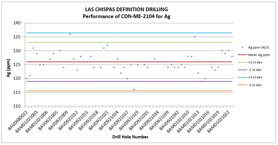
Source: P&E, 2024.
| |
| Figure 8‑5: | Definition Drilling CRM CDN-ME 1902 Analysis for Gold |

Source: P&E, 2024.
| Figure 8‑6: | Definition Drilling CRM CDN-ME 1902 Analysis for Silver |

Source: P&E, 2024.
| |
| Figure 8‑7: | Definition Drilling CRM LC-2022-LOW Analysis for Gold |

Source: P&E, 2024.
| Figure 8‑8: | Definition Drilling CRM LC-2022-LOW Analysis for Silver |
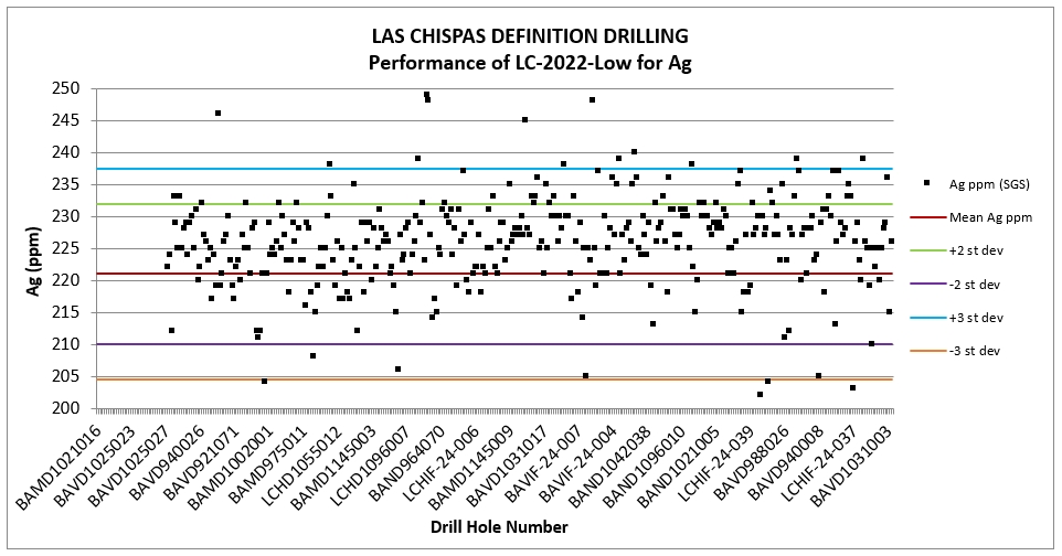
Source: P&E, 2024.
| |
| Figure 8‑9: | Definition Drilling CRM LC-2022-MID Analysis for Gold |

Source: P&E, 2024.
| Figure 8‑10: | Definition Drilling CRM LC-2022-MID Analysis for Silver |

Source: P&E, 2024.
| |
| Figure 8‑11: | Definition Drilling CRM LC-2022-HIGH Analysis for Gold |

Source: P&E, 2024.
| Figure 8‑12: | Definition Drilling CRM LC-2022-HIGH Analysis for Silver |

Source: P&E, 2024.
| |
Multiple CRMs covering a range of gold and silver grades were used, including overlimit values, allowing for a more robust assessment of the QA/QC database. Assessment of the CRM performance concluded that collectively, all six (6) CRMs performed reasonably, with an overall failure rate of 2% for gold and 4% for silver at ALS, and 2% for gold and 3% for silver at SGS. The CDN-ME-1805 CRM (only sent to ALS) again recorded the most failures for both gold and silver (refer to Table 8‑3); however, this CRM accounts for only 8% of the CRMs sent to ALS during this phase of drilling. The primary CRM used at ALS (the CDN-ME-1902) throughout the most recent phase of definition drilling, constitutes 80% of the total CRM data and returned relatively few failures, with failure rates of 1% for gold and 4% for silver. The primary CRMs used at SGS (the LC-2022-LOW and LC-2022-MID), constitute 90% of the total CRM data at SGS and returned failure rates of 2% for gold and 4% for silver for the LC-2022-LOW standard and 2% for both gold and silver for the LC-2022-MID standard.
| 8.6.7.2 | Blanks |
In order to monitor for contamination, or contamination of sample crushing, grinding, and sorting equipment, non-mineralized rock samples were inserted at an interval of one for every 12 samples (8.4%). The material used for the coarse blanks was collected from a nearby barren outcrop. A total of 2,900 blank insertions were recorded in the database reviewed by the QP. The results of the Blank performance analysis for sampling completed from July 2022 to October 2024 are graphed in Figure 8-13 and Figure 8-14.
The failure threshold for the blanks is 10 times the detection limits of the analytical equipment. Material contamination was not identified in the analytical stream, and the QP does not consider contamination to be a concern for the Mineral Resource Estimate.
| Figure 8‑13: | Analytical Results for Gold Grades from Definition Drilling QA/QC Blank Sample Insertions |

Source: P&E, 2024.
| |
| Figure 8‑14: | Analytical Results for Silver Grades from Definition Drilling QA/QC Blank Sample Insertions |

Source: P&E, 2024.
| 8.6.7.3 | Duplicates |
Insufficient field duplicate samples were taken to undertake meaningful review, and laboratory duplicates were not analyzed by the QP for the definition drilling sample data.
| 8.6.8 | Phase V QA/QC Program – Exploration Drilling at (Jul 2022 to Oct 2024) |
All exploration drill core samples were analyzed at ALS from the period of July 2022 to January 2024 and at SGS, Arizpe from January 2024 until October 2024. The QA/QC program used for these samples is summarized below.
| 8.6.8.1 | Certified Reference Materials |
Commercial standards and Las Chispas custom standards were purchased from CDN Labs in pre-packaged sachets. The CRM insertion frequency was one to every 49 samples (2%) for the exploration drilling samples.
A total of 93,766 exploration drill core samples were analyzed for drilling carried out from July 2022 to October 2024. A total of 1,897 CRMs were inserted into the sample stream during this phase of drilling. Each CRM and corresponding sample number was recorded in a QA/QC sample tracking spreadsheet. Results >2 SD and <3 SD were flagged as cautionary for review.
A CRM failure was defined by receipt of analytical results that were >3 SD above or below the expected gold or silver grade. The protocol for re-assaying the CRM failures was to re-analyze the pulps within a range of 10 samples above and 10 samples below the failed CRM. In cases where the CRM failures occurred in a batch of samples consisting of “non-mineralized” rock (generally in zones returning <0.1 g/t Au or <5 g/t Ag), no action was taken. The expected values and failure rates for the CRMs are shown in Table 8-6. The results of the CRM performance analysis for sampling completed from July 2022 to October 2024 are graphed in Figure 8-15 to Figure 8-24.Source: P&E, 2023.
| |
| Table 8‑6: | Standards Expected Au and Ag Values and the Failure Rates for Jul 2022 to Oct 2024 Exploration Drilling |
| Standards | Expected Au | Expected Ag | ALS | SGS | ||||
| Values, ± 3SD | Values, ± 3SD | Sent | Au Failures | Ag Failures | Sent | Au Failures | Ag Failures | |
| (g/t) | (g/t) | (N=) | (%) | (%) | (N=) | (%) | (%) | |
| CDN-ME-1805 | 2.67, ±0.255 | 2,236, ±111 | 13 | 0.0 | 0.0 | 10 | 10.0 | 10.0 |
| CDN-ME-1902 | 5.38, ±0.63 | 356, ±28.50 | 1405 | 1.0 | 4.9 | 227 | 0.9 | 7.5 |
| LC-2022-LOW | 1.95, ±0.18 | 221, ±16.50 | 19 | 5.3 | 0.0 | 108 | 1.9 | 2.8 |
| LC-2022-MID | 5.84, ±0.54 | 567, ±34.50 | -- | -- | -- | 122 | 0.0 | 0.0 |
| LC-2022-HIGH | 7.76, ±0.60 | 1,156, ±70.5 | -- | -- | -- | 3 | 33.3 | 33.3 |
| Total | 1437 | 1.0 | 4.8 | 460 | 1.1 | 4.6 | ||
Source: P&E, 2024.
| Figure 8‑15: | Exploration Drilling CRM CDN-ME 1805 Analysis, Gold |

Source: P&E, 2024.
| |
| Figure 8‑16: | Exploration Drilling CRM CDN-ME-1805 Analysis for Silver |
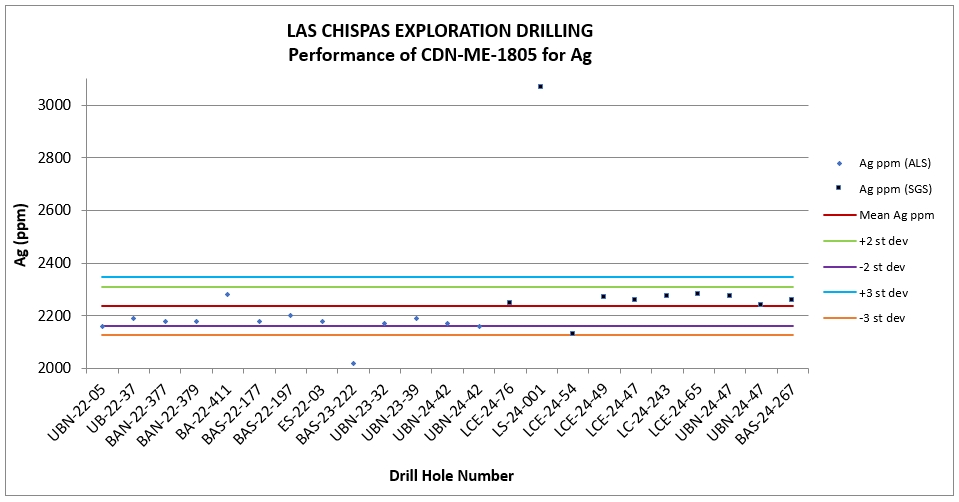
Source: P&E, 2024.
| Figure 8‑17: | Exploration Drilling CRM CDN-ME 1902 Analysis for Gold |

Source: P&E, 2024.
| |
| Figure 8‑18: | Exploration Drilling CRM CDN-ME 1902 Analysis for Silver |
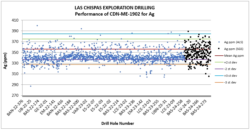
Source: P&E, 2024.
| Figure 8‑19: | Exploration Drilling CRM LC-2022-LOW Analysis for Gold |
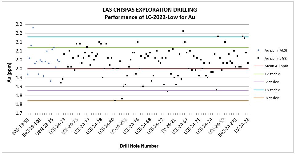
Source: P&E, 2024.
| |
| Figure 8‑20: | Exploration Drilling CRM LC-2022-LOW Analysis for Silver |

Source: P&E, 2024.
| Figure 8‑21: | Exploration Drilling CRM LC-2022-MID Analysis for Gold |
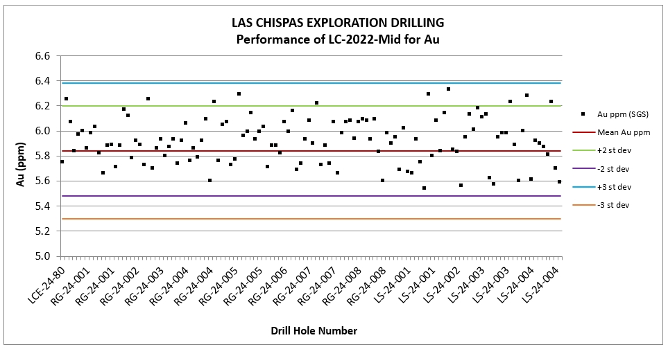
Source: P&E, 2024.
| |
| Figure 8‑22: | Exploration Drilling CRM LC-2022-MID Analysis for Silver |
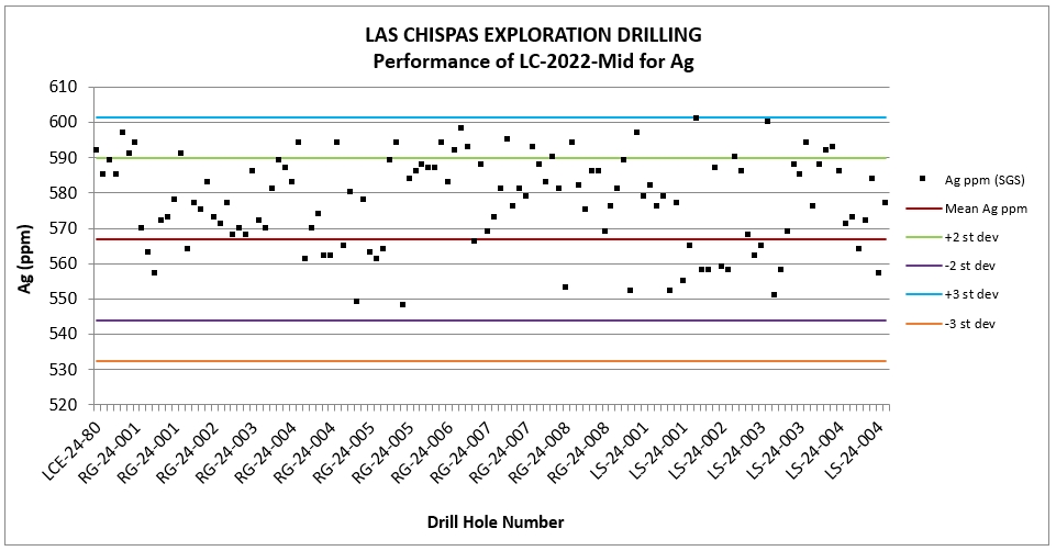
Source: P&E, 2024.
| Figure 8‑23: | Exploration Drilling CRM LC-2022-HIGH Analysis for Gold |

Source: P&E, 2024.
| |
| Figure 8‑24: | Exploration Drilling CRM LC-2022-HIGH Analysis for Silver |
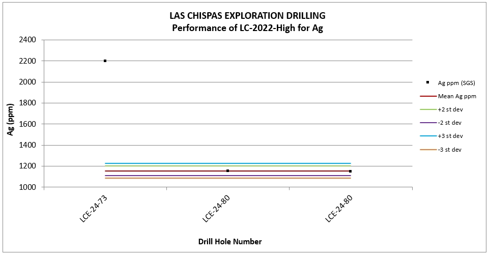
Source: P&E, 2024.
Multiple CRMs covering a range of gold and silver grades were used, including overlimit values, as for the definition drilling program. Assessment of the CRM performance concluded that collectively, all five (5) CRMs performed reasonably, with an overall failure rate of 1% for gold and 5% for silver at ALS, and 1% for gold and 5% for silver at SGS. Relatively high failure rates were recorded for the LC-2022-HIGH standard for both gold and silver and the CDN-ME-1805 standard for silver; however, these standards were used briefly, and the failures are not statistically significant. The CDN-ME-1902 CRM recorded the most failures (7.5% failure rate) for silver at SGS (see Table 8‑3). All other CRMs returned relatively few failures with failure rates of <5% for gold and silver at both laboratories.
| 8.6.8.2 | Blanks |
In order to monitor for contamination, or contamination of sample crushing, grinding, and sorting equipment, non-mineralized rock samples were inserted at an interval of one for every 16 samples (6.3%). The material used for the coarse blanks was collected from a nearby barren outcrop. A total of 5,935 blank insertions were recorded in the database reviewed by the QP. The results of the Blank performance analysis for sampling completed from July 2022 to October 2024 are graphed in Figure 8-25 and Figure 8-26.
The failure threshold for the blanks is 10 times the detection limits of the analytical equipment. Material contamination was not identified in the analytical stream, and the QP does not consider contamination to be a concern for the Mineral Resource Estimate.
| |
| Figure 8‑25: | Analytical Results for Gold Grades from Definition Drilling QA/QC Blank Sample Insertions |
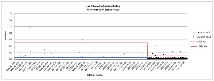
Source: P&E, 2024.
| Figure 8‑26: | Analytical Results for Silver Grades from Definition Drilling QA/QC Blank Sample Insertions |
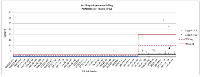
Source: P&E, 2024.
| 8.6.8.3 | Duplicates |
Field and laboratory pulp duplicate data were examined for the Phase V exploration drilling program at the Property. A total of 203 gold and silver field duplicates analyzed at ALS, and 57 at SGS, were reviewed by the QP. Data were plotted on scatter charts (Figure 8.27 to Figure 8.30) and the R2 value for the gold field duplicates estimated at 0.962 for the ALS data and 0.927 for SGS, and 0.979 and 0.936, respectively, for the silver field duplicates.
| |
There were 205 gold and silver field duplicates analyzed at ALS and 51 at SGS. Scatter chart plots estimated the R2 value for the gold laboratory duplicates at 0.935 for the ALS data and 0.997 for SGS, and 0.954 and 1, respectively, for the silver lab duplicates. The QP considers precision at both the field and pulp level to be acceptable.
| Figure 8‑27: | Exploration Drilling Field Duplicate Analytical Results for Gold |
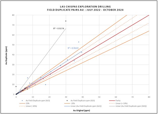
Source: P&E, 2024.
| |
| Figure 8‑28: | Exploration Drilling Field Duplicate Analytical Results for Silver |

Source: P&E, 2024.
| |
| Figure 8‑29: | Exploration Drilling Laboratory Duplicate Analytical Results for Gold |

Source: P&E, 2024.
| |
| Figure 8‑30: | Exploration Drilling Laboratory Duplicate Analytical Results for Silver |
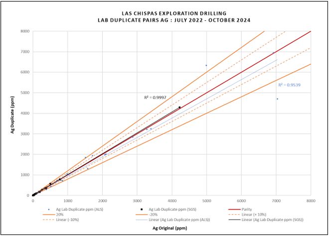
Source: P&E, 2024.
| 8.6.9 | Phase V QA/QC Program – Underground Channel Samples |
All samples from the underground channel sampling at the Property were analyzed at SGS, Arizpe and a QA/QC program was implemented to monitor the quality of the assay results as presented below.
| 8.6.9.1 | Certified Reference Materials |
Commercial and Las Chispas custom CRMs were purchased from CDN Labs in pre-packaged sachets. A total of 26,147 samples were sent to the SGS-Arizpe facility between July 2022 to October 2024. A total of 1,677 CRMs were inserted into the sample stream at a frequency of 1 CRM per sampled face (~1:16 samples). Each CRM and corresponding sample number were recorded in a QA/QC sample tracking spreadsheet. Results >2 SD and <3 SD were flagged as cautionary for review.
The expected values and failure rates of the CRMs are shown in Table 8-7. The results of the CRM performance analysis for sampling completed from July 2022 to October 2024 are shown in Figure 8-31 to Figure 8-40.
| |
| Table 8‑7: | Standards Expected Au and Ag Values and the Failure Rates for SGS-Arizpe, July 2022 to October 2024 Underground Channel Sampling |
| Standards | Expected Au | Expected Ag Values, ± 3SD (g/t) | SGS | ||
Values, ± 3SD (g/t) | Sent (N=) | Au Failures (%) | Ag Failures (%) | ||
| CDN-ME-1805 | 2.67, ± 0.255 | 2,236, ± 111 | 269 | 5.9 | 8.2 |
| CDN-ME-2104 | 2.388, ± 0.348 | 126, ± 10.50 | 430 | 0.7 | 5.1 |
| CDN-ME-1902 | 5.38, ± 0.63 | 356, ± 28.50 | 47 | 0.0 | 4.3 |
| LC-2022-LOW | 1.95, ± 0.18 | 221, ± 16.50 | 454 | 5.3 | 5.1 |
| LC-2022-MID | 5.84, ± 0.54 | 567, ± 34.50 | 289 | 0.7 | 1.4 |
| LC-2022-HIGH | 7.76, ± 0.60 | 1,156, ± 70.5 | 188 | 2.7 | 2.1 |
| Total | 1,677 | 3.0 | 4.6 | ||
Source: P&E, 2024.
| Figure 8‑31: | Underground Channel Sampling CRM CDN-ME-1805 Analysis for Gold |

Source: P&E, 2024.
| |
| Figure 8‑32: | Underground Channel Sampling CRM CDN-ME-1805 Analysis for Silver |

Source: P&E, 2024.
| Figure 8‑33: | Underground Channel Sampling CRM CDN-ME-1902 Analysis for Gold |

Source: P&E, 2024.
| |
| Figure 8‑34: | Underground Channel Sampling CRM CDN-ME-1902 Analysis for Silver |

Source: P&E, 2024.
| Figure 8‑35: | Underground Channel Sampling CRM LC-2022-LOW Analysis for Gold |
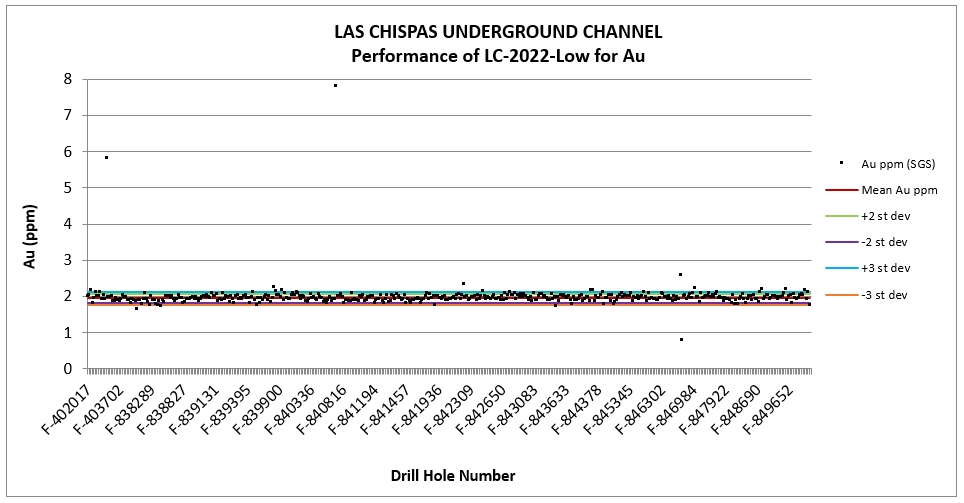
Source: P&E, 2024.
| |
| Figure 8‑36: | Underground Channel Sampling CRM LC-2022-LOW Analysis for Silver |

Source: P&E, 2024.
| Figure 8‑37: | Underground Channel Sampling CRM LC-2022-MID Analysis for Gold |
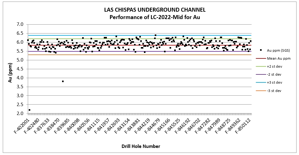
Source: P&E, 2024.
| |
| Figure 8‑38: | Underground Channel Sampling CRM LC-2022-MID Analysis for Silver |
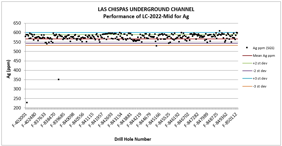
Source: P&E, 2024.
| Figure 8‑39: | Underground Channel Sampling CRM LC-2022-HIGH Analysis for Gold |
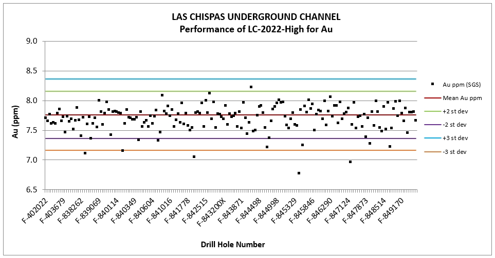
Source: P&E, 2024.
| |
| Figure 8‑40: | Underground Channel Sampling CRM LC-2022-HIGH Analysis for Silver |

Source: P&E, 2024.
Multiple CRMs covering a range of gold and silver grades were used, including overlimit values, as for the definition and exploration drilling programs. Assessment of the CRM performance concluded that collectively, all six (6) CRMs performed reasonably, with an overall failure rate of 3% for gold and 5% for silver (all samples were analyzed at SGS laboratory only). Relatively high failure rates were again apparent for the CDN-ME-1805 standard for both gold and silver, with failure rates of 5.9% and 8.2%, respectively (see Table 8-7). All other CRMs returned relatively few failures with failure rates of 5% or lower for both gold and silver.
| 8.6.9.2 | Blanks |
To monitor for contamination, or contamination of sample crushing, grinding, and sorting equipment, non-mineralized rock samples were inserted at an interval of one for every 16 samples (6.4%). The material used for the coarse blanks was collected from a nearby barren outcrop. A total of 1,172 blank insertions were observed in the database reviewed by the QP. The results of the Blank performance analysis for sampling completed from July 2022 to October 2024 are shown in Figure 8-41 and Figure 8-42.
The failure threshold for the blanks is 10 times the detection limit of the analytical equipment. Material contamination was not identified in the analytical stream, and the QP does not consider contamination to be a concern for the Mineral Resource Estimate.
| |
| Figure 8‑41: | Analytical Results for Gold Grades from Underground Channel Sampling QA/QC Blank Sample Insertions |

Source: P&E, 2024.
| Figure 8‑42: | Analytical Results for Ag Grades from Underground Channel Sampling QA/QC Blank Sample Insertions |

Source: P&E, 2024.
| 8.6.9.3 | Duplicates |
Field and laboratory coarse reject duplicate data were examined for the Phase V underground channel sampling at the Property. Field duplicate samples were obtained from the same channel section as the original sample, but 10 cm below the original sample. A total of 834 gold and silver field duplicates and 282 coarse reject duplicates, analyzed at SGS, were examined. Data were plotted on scatter charts (Figure 8.43 to Figure 8.46) and the R2 value for the gold field duplicates was estimated at 0.792 and 0.827 for silver, and 0.995 and 0.997, respectively, for the coarse reject duplicates. Precision for the channel sample field duplicates is poor for both gold and silver, but consistent with expectations for this type of sampling. An obvious improvement is noted in the coarse reject duplicates with excellent precision displayed at the coarse reject level. The QP considers precision at both the field and coarse reject level to be acceptable.
| |
| Figure 8‑43: | Underground Channel Sampling Field Duplicate Analytical Results for Gold |
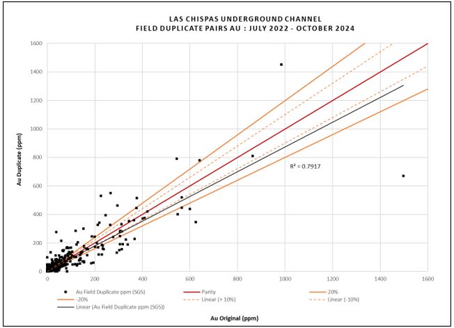
Source: P&E, 2024.
| |
| Figure 8‑44: | Underground Channel Sampling Field Duplicate Analytical Results for Silver |

Source: P&E, 2024.
| |
| Figure 8‑45: | Underground Channel Sampling Coarse Reject Duplicate Analytical Results for Gold |

Source: P&E, 2024.
| |
| Figure 8‑46: | Underground Channel Sampling Coarse Reject Duplicate Analytical Results for Silver |

Source: P&E, 2024.
| 8.7 | Comments on Sample Preparation, Analysis and Security |
The sample preparation, analysis, and security program implemented at Las Chispas Operations was designed with the intent to support collection of a large volume of data. Sample collection and handling routines were well documented. The laboratory analytical methods, detection limits, and grade assay limits are suited to the style, grade and distribution of mineralization.
The QA/QC methods implemented at the Property enabled assessment of sample security, assay accuracy, precision, and potential for contamination. There were no other significant concerns related to the integrity of sample collection and analysis.
Quality Assurance procedures are instituted at the Las Chispas Operations and the QP reviewed sample collection and handling procedures, including standard operating procedures, laboratory analytical methods, QA/QC methods, and QA/QC program results and considers these methods are adequate to support the current Mineral Resource Estimate.
| |
| 9 | DATA VERIFICATION |
| 9.1 | Data Verification and Validation |
| 9.1.1 | P&E Data Verification |
Prior to Coeur Mining’s acquisition, Las Chispas Operations developed an extensive dataset for Las Chispas that is stored and managed using a Geospark™ database. The QPs of this Chapter have reviewed the data compilation and have audited the Geospark™ database.
The QPs completed verification of the Las Chispas databases for gold and silver by comparison of the database entries with assay certificates in comma-separated values (.csv) and Excel (.xls) file formats, obtained directly by the QPs from ALS Webtrieve™ and SGS QLab.
Assay data were previously verified for five separate datasets: Las Chispas, Las Chispas Underground, Babicanora Underground, William Tell Underground, and Babi Vista.
Assessment of the Las Chispas data was carried out on the constrained data only and involved verification of 95% (4,440 out of 4,662 samples) of that data. A total of four discrepancies were observed.
Assessment of the Las Chispas Underground data was also undertaken on the constrained data only, with verification of 42% (2,821 of 3,884 samples) of that data completed. No discrepancies were encountered.
Babicanora Underground constrained data involved verification of 13% (132 out of 1,011 samples) of the data and three discrepancies were encountered.
All data for the William Tell Underground dataset were included in the verification data, with a total of 42% (128 out of 305 samples) of the data verified. No errors were encountered during the verification process.
Assessment of the Babi Vista data was undertaken on the constrained data only and involved verification of 98% (189 out of 192 samples) of that data, with no errors encountered.
The QPs of this Chapter completed further verification of the Las Chispas assay data for gold and silver in December of 2024. Assay data ranging from July 2022 to October 2024 were verified for the Las Chispas definition drilling, exploration drilling and surface chip-channel datasets. Just over 10% of the definition drilling assay data (3,634 of 34,706 samples) and surface chip-channel data (1,806 of 17,935 samples) were verified for gold and silver. 20% of the exploration drilling assay data (20,266 of 93,766 samples) were also verified for gold and silver. Very few minor errors were encountered in the data during the December 2024 verification process, which are not considered material to the current Mineral Resource Estimate. The QPs of this Report Chapter consider the databases provided to be reliable and do not consider the few minor discrepancies encountered during the verification process to be of material impact to the Mineral Resource data.
| 9.1.2 | Data Validation |
The QPs also validated the Mineral Resource database in GEMS™ by checking for inconsistencies in analytical units, duplicate entries, interval, length or distance values less than or equal to zero, blank or zero-value assay results, out-of-sequence intervals, intervals or distances greater than the reported drill hole length, inappropriate collar locations, survey and missing interval and coordinate fields. A few errors were identified and corrected in the database.
| |
| 9.2 | Site Visits and Independent Sampling |
| 9.2.1 | P&E Site Visit and Independent Sampling March 2022 |
The Las Chispas Operation was visited by Mr. David Burga, P.Geo., of P&E from March 12 to 14, 2022, for the purpose of completing a site visit that included visiting surface and underground drilling and channel sampling sites, verifying the location of select drill hole collars, discussions with technical personnel, and due diligence sampling.
Mr. Burga arrived on site on the afternoon of March 12, 2022, and toured the northeastern side of the Property, where drill holes BV-21-343, BV-21-353, BV-21-380, and BV21-382 are located. The following day, Mr. Burga met with the Las Chispas Operations geology team and viewed a presentation of the Mineral Resource, the mineralized structures on the Property, and the underground mine layout. Mr. Burga also reviewed the sampling protocols and procedures used at Las Chispas. An underground tour was completed later by one of Las Chispas Operations mine geologists. Access to the mine was gained through the Santa Rosa portal and an active sampling face was visited during the tour. The geologist marked the mineralized structure and the sites for sampling. Subsequently, a mat was used to collect the sample. The site visit QP considers that the sampling was completed to industry standards.
On March 14, 2022, Mr. Burga completed independent core sampling by collecting 32 samples from 16 diamond drill holes. A list of various potential samples was sent to Las Chispas Operations in advance of the site visit; however, the specific samples selected were not known to them prior to the QP’s arrival. All samples were selected from drill holes completed in 2021 and 2022. A range of high-, medium- and low-grade samples were selected from the stored NQ-sized drill core. Samples were collected by taking a quarter drill core, with the other quarter core remaining in the drill core box. Particular care was taken to collect the fines during the sampling process. Each sample was placed in a plastic bag with a uniquely numbered tag, before being securely closed. All samples were then collectively placed in a larger bag. Mr. Burga sent the samples by courier directly to the ALS laboratory in Hermosillo for analysis.
Following independent sample collection, Mr. Burga verified more collar locations by GPS and a portable drill rig set- up on drill hole BV-22-214.
Samples at ALS were analyzed for gold and silver by fire assay with gravimetric finish. Bulk density determinations were also made for each of the samples.
ALS has developed and implemented strategically designed processes and a global quality management system at each of its locations. The global quality program includes internal and external inter-laboratory test programs and regularly scheduled internal audits that meet all requirements of ISO/IEC 17025:2017 and ISO 9001:2015. All ALS geochemical hub laboratories are accredited to ISO/IEC 17025:2017 for specific analytical procedures.
A comparison of the P&E independent sample verification results versus the original assay results are presented in Figure 9‑1 and Figure 9‑2.
| |
| Figure 9‑1: | March 2022 Site Visit Sample Comparison for Gold |

Source: P&E, 2023.
| Figure 9‑2: | March 2022 Site Visit Sample Comparison for Silver |
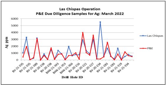
Source: P&E, 2023.
| |
| 9.2.2 | P&E Site Visit and Independent Sampling December 2024 |
The Las Chispas Operation was visited again by Mr. David Burga, P.Geo., of P&E from December 3 to 4, 2024, for the purpose of completing a site visit that included visiting surface and underground drilling and channel sampling sites, verifying the location of select drill collars, discussions with technical personnel, and due diligence sampling.
Mr. Burga also reviewed the sampling protocols and procedures used at Las Chispas. An underground tour was later completed with one of Las Chispas Operations mine geologists. Access to the mine was gained through the Santa Rosa portal and an active sampling face was visited during the tour. The geologist marked the mineralized structure and the locations to be sampled. Subsequently, a mat was used to collect the sample. The site visit QP considers that the sampling was completed to industry standards.
On December 4, 2024, Mr. Burga completed independent core sampling, collecting 17 samples from nine diamond drill holes. A list of potential samples was sent to Las Chispas Operations prior to the site visit; however, the specific samples selected were not known to Operations personnel prior to the QP’s arrival. All samples were selected from drill holes completed in 2023 and 2024. A range of high-, medium- and low-grade samples were selected from the stored drill core. Samples were collected by taking a quarter drill core, with the other quarter core remaining in the drill core box. Particular care was taken to collect the fines during the sampling process. Each sample was placed in a plastic bag with a uniquely numbered tag before being securely closed. All samples were then collectively placed in a larger bag. Mr. Burga sent the samples by courier directly to the ALS laboratory in Hermosillo for analysis.
Following independent sample collection, Mr. Burga verified more collar locations by GPS.
Samples at ALS, an ISO/IEC 17025:2017 accredited laboratory, were analyzed for gold and silver by fire assay with gravimetric finish. Bulk density determinations were also taken on all samples.
A comparison of the P&E 2024 independent sample verification results versus the original assay results are presented in Figure 9‑3 and Figure 9-4.
| |
| Figure 9‑3 | December 2024 Site Visit Sample Comparison for Gold |

Source: P&E, 2024.
| Figure 9‑4: | December 2024 Site Visit Sample Comparison for Silver |
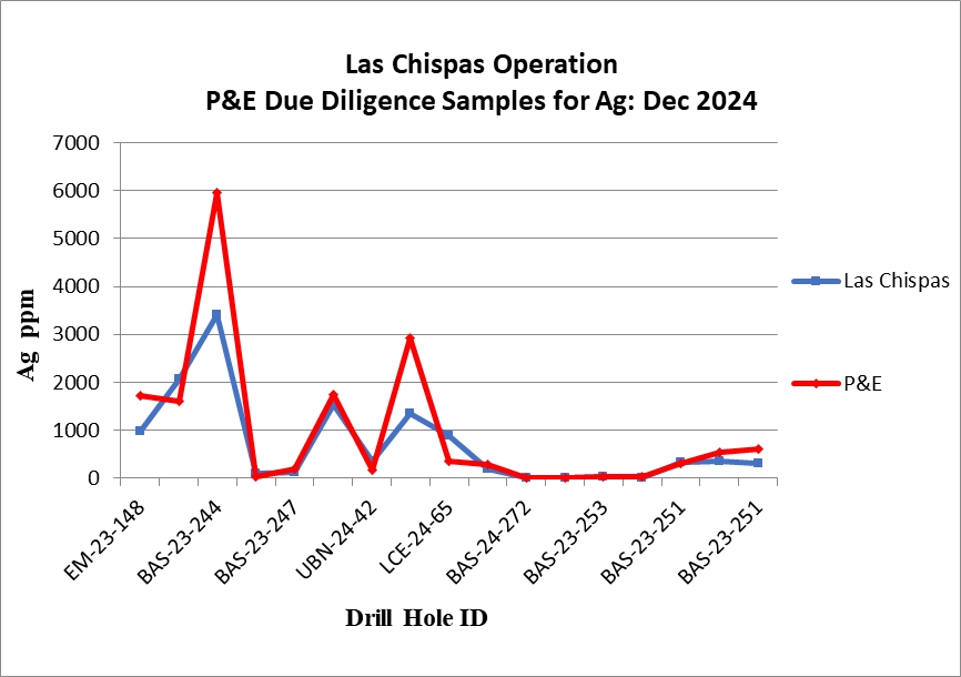
Source: P&E, 2024.
| |
Additional QP site inspections are noted in Section 2.4.
| 9.3 | Processing, Environmental and Permitting Data Verification |
James Millard conducted a data verification process by reviewing the environmental and permitting reports included in this document. His review focused on ensuring the accuracy, consistency, and completeness of the information presented, aligning with regulatory requirements and industry best practices.
| 9.4 | Comments on Data Verification |
The independent site visit samples match closely to the Las Chispas Operation data for both gold and silver, and the QPs consider the the due diligence results to be acceptable.
Based on the assessment of the QA/QC program previously undertaken at Las Chispas Operations, and due diligence sampling and database verification, it is the QPs' opinion that the data are robust and suitable for use in the current Mineral Resource Estimate.
| |
| 10 | MINERAL PROCESSING AND METALLURGICAL TESTING |
| 10.1 | Introduction |
Mineral deposits in the Las Chispas district are classified as gold and silver, low to intermediate sulphidation epithermal systems, typical of many deposits in northeastern Sonora and are mined using variations of longhole stoping and cut and fill mining methods via several access drifts and ramps. Ore is processed through a primary jaw crusher, SAG mill in closed circuit with hydrocyclones, cyanide leaching, Merrill-Crowe metal recovery and tailings filtration. Section 14 shows the detailed explanation of the recovery process.
| 10.2 | Process Plant Operating Performance |
The Las Chispas plant began operations in June 2022, with operating data becoming available shortly afterwards. During 2024, feed material to the Process Plant was made up of ore from the Babicanora Main zone (BAM), Babicanora Central Zone (BAC), Babicanora Norte zone (BAN), Babi-Vista zone (BAV), and the historic stockpiles (HS).
The current operating strategy of bypassing the flotation circuit and processing the whole ore stream through the bulk leach circuit at ~2,000mg/L free cyanide is achieving expected gold and silver recoveries. The detox circuit has been modified to operate on solution or on slurry but is typically being by-passed. The operating strategy is linked to maintaining solution in the North Pond below the ICMC limits.
| 10.2.1 | Gold Recovery |
The operating data for gold recovery is presented in Figure 10‑1 as a function of time in 2024.
| Figure 10‑1: | 2024 Daily Operating Gold Recoveries at Las Chispas |
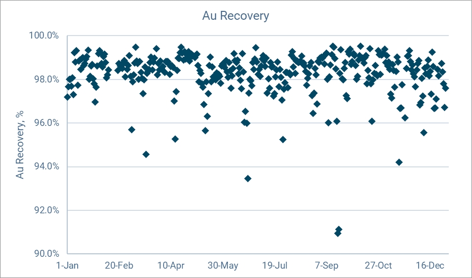
Source: Ausenco, 2025.
| |
The recovery in 2024 has been consistent between 98% and 99% demonstrating that the process is efficient and stable. The recoveries dropped below 97% due to sporadic operational issues in the process plant.
The operating data is presented in Figure 10‑2 with test results from the 2021 FS Report to demonstrate that the plant is meeting or exceeding recovery expectations.
| Figure 10‑2: | Gold Recovery as a Function of Head Grade |

Source: Ausenco, 2025.
Based on the operating data and the ongoing blending strategy of the operation, it has been decided to maintain a fixed recovery estimate of 98% for Au for the operation.
| 10.2.2 | Silver Recovery |
The operating data for silver recovery is presented in Figure 10‑3 as a function of time in 2024.
Silver recovery was consistent through 2024. Operating data for silver recovery as well as historical test work is presented in Figure 10‑3 and Figure 10‑4.
Based on the operating data and the ongoing blending strategy of the operation, it has been decided to use a fixed recovery estimate of 97% for Ag for the operation.
| |
| Figure 10‑3: | 2024 Daily Operating Silver Recoveries as a Function of Time |

Source: Ausenco, 2025.
| Figure 10‑4: | Silver Recovery as a Function of Head Grade |

Source: Ausenco, 2025.
| |
| 10.2.3 | Recovery Projections |
Table 10‑1 presents the average gold and silver recovery forecasts calculated from the analysis of all testwork results, operating data and blending strategy with operations of the Las Chispas (whole ore leach) flowsheet.
| Table 10‑1: | Forecast Life of Mine Average Au and Ag Recovery |
| Processing Flowsheet | Overall Recovery (%) | |
| Au | Ag | |
| WOL | 98.0 | 97.5 |
| 10.3 | Comments on Mineral Processing and Metallurgical Testing |
The QP had full access to the operational data. The data demonstrates that Las Chispas Process Plant continues to operate well and there is nothing indicating that the Process Plant will not continue achieving the gold and silver recoveries indicated.
Operating data from 2024 was reviewed and compared to the testwork. Both gold and silver recoveries using a WOL flowsheet with >2,000 mg/L free cyanide presented better results when compared to the testwork.
Based on the analysis and comparison of laboratory testwork and current plant operations of grade blending and whole ore cyanide leach, it is reasonable to use fixed LOM recoveries of 98.0% for Au and 97.5% for Ag for blended mill feed materials of >3 g/t Au and >350 g/t Ag.
| |
| 11 | MINERAL RESOURCE ESTIMATES |
| 11.1 | Introduction |
The purpose of this Technical Report Summary section is to present the 2024 Las Chispas Operations Mineral Resource Estimate, which is based on drilling and underground sampling programs as of October 31, 2024. This initial Mineral Resource Estimate includes in-situ narrow vein gold and silver mineralization in the Babicanora and Las Chispas Areas.
The Mineral Resources Estimate presented herein is reported in accordance with S-K 1300. Confidence in the estimate of an Inferred Mineral Resource is insufficient to allow the meaningful application of technical and economic parameters, or to enable an evaluation of economic viability worthy of public disclosure. Mineral Resources may be affected by further infill and exploration drilling that may result in increases or decreases in subsequent Mineral Resource Estimate. Mineral Resources in this Estimate are stated exclusive of the Mineral Reserves stated in Section 12.
This Mineral Resource Estimate was undertaken with Leapfrog™ software by Las Chispas Operations, and was reviewed and accepted by Yungang Wu, P.Geo. and Eugene Puritch, P.Eng., FEC, CET of P&E Mining Consultants Inc. (P&E) of Brampton, Ontario. Messrs. Wu and Puritch are independent of Coeur Mining as defined in S-K 1300.
The effective date of this Mineral Resource Estimate is December 31, 2024.
| 11.2 | Database |
The database supporting this Mineral Resource Estimate consisted of exploration drilling, definition drilling and underground channel and chip samples for the in-situ narrow veins in both Babicanora and Las Chispas Areas (Table 11‑1). The database cut-off data was October 31, 2024. Babicanora and Las Chispas drill hole plans are shown in Figure 11‑1 and Figure 11‑2.
| Table 11‑1: | Drillhole Database Summary |
| Data Type | Total Number | Total Meters |
| Exploration GeoSpark Database Drill Holes* | 2,572 | 755,224 |
| Mine Geology GeoSpark Database Drill Holes | 1,958 | 108,790 |
| Total Drill Holes | 4,530 | 864,014 |
| Underground Channel Samples in Babicanora and Las Chispas Areas | 28,102 | 19,843 |
| Underground Channel/chip Samples (point data) in Las Chispas Area only** | 6,511 | NA |
Note: * 12 water well drill holes named with POZO were excluded. ** Muck samples were excluded
| |
| Figure 11‑1: | Babicanora Drill Hole Plan |

Source: P&E, 2025
| |
| Figure 11‑2: | Las Chispas Drill Hole Plan |

Source: P&E, 2025
The database contains assays for gold and silver and other elements of non-economic importance. The basic gold and silver raw assay statistics are presented in Table 11‑2.
| |
| Table 11‑2: | Las Chispas Assay Database Summary |
| Dataset | Variable | Au | Ag |
| Drill Holes | Number of Samples | 332,485 | 332,487 |
| Minimum Value * | 0.001 | 0.20 | |
| Maximum Value * | 3,366 | 114,814 | |
| Mean * | 0.29 | 25.35 | |
| Median * | 0.05 | 0.90 | |
| Variance | 78.03 | 326,428 | |
| Standard Deviation | 8.83 | 571.34 | |
| Coefficient of Variation | 30.52 | 22.54 | |
| Skewness | 210.22 | 83.03 | |
| Kurtosis | 68,811 | 10,401 | |
| UG Channel/Chip Samples | Number of Samples | 28,102 | 28,102 |
| Minimum Value * | 0.005 | 0.20 | |
| Maximum Value * | 2,766.00 | 266,110.00 | |
| Mean * | 6.00 | 587.45 | |
| Median * | 0.05 | 10.00 | |
| Variance | 1,822.68 | 15,083,427.98 | |
| Standard Deviation | 42.69 | 3,883.74 | |
| Coefficient of Variation | 7.11 | 6.61 | |
| Skewness | 25.04 | 24.55 | |
| Kurtosis | 1,033.39 | 1,091.46 | |
| UG Channel/Chip Samples of Las Chispas Area | Number of Samples | 6,511 | 6,511 |
| Minimum Value * | 0.002 | 0.20 | |
| Maximum Value * | 136.00 | 10,000 | |
| Mean * | 0.78 | 118.85 | |
| Median * | 0.05 | 9.00 | |
| Variance | 10.35 | 168,938 | |
| Standard Deviation | 3.22 | 411.02 | |
| Coefficient of Variation | 4.14 | 3.46 | |
| Skewness | 17.75 | 10.32 | |
| Kurtosis | 564.44 | 171.97 |
Note: UG = underground. *Au and Ag units are g/t.
All drill hole survey and assay values are expressed in metric units, with grid coordinates reported using the WGS84, Zone 12N UTM system.
| |
| 11.3 | Data Verification |
The QPs verified the Mineral Resource database by checking for inconsistencies in analytical units, duplicate entries, interval, length, or distance values less than or equal to zero, blank or zero-value assay results, out-of-sequence intervals, intervals, or distances greater than the reported drill hole length, inappropriate collar locations, survey and missing interval and coordinate fields. A few errors were identified and corrected in the databases. A total of 358 drill holes and 335 underground channel samples in the Babicanora area and 298 underground channel/chip samples in the Las Chispas area were ignored from the Mineral Resource Estimate, mainly due to a higher level of confidence in the closely spaced delineation drilling and underground development sampling data. The QPs are of the opinion that the supplied database is suitable for Mineral Resource estimation.
| 11.4 | Domain Interpretation |
The mineralized vein wireframes were interpreted and constructed by Las Chispas Operations using Seequent Limited Leapfrog® Geo. The QPs reviewed the vein models and consider the wireframes to reasonably represent the assay data and are suitable for Mineral Resource estimation.
Models were developed for each vein by manually tagging drill hole and channel sample intercepts using the drill core field logs, maps, and assays. The vein models represent the continuous zones of structurally hosted gold and silver mineralization and the structural extensions of the veins, which were named as “unclipped” solids.
A total of 76 unclipped wireframes (50 in Babicanora area and 26 in Las Chispas area) were developed to represent the mineralized veins and splays. The “unclipped” solids were clipped to include mineralized areas with ≥150 g/t AgEq (where AgEq = Ag g/t + (Au g/t * 79.51)). The clipping boundary was placed at the midpoint of the drill hole intercepts ≥150 g/t AgEq and the drill hole intersects <150 g/t AgEq; the clipped solid was extended a maximum distance of 60 m from drill hole intercepts into untested areas along strike and down-dip. In some cases, samples <150 g/t AgEq were included within the clipped domain to maintain the mineralized continuity. Minimum mining width was not applied, and the mineralized vein wireframe is considered to be undiluted. The clipped wireframes were used as constraining boundaries during Mineral Resource estimation, for rock coding, statistical analysis, and compositing limits. The Babicanora and Las Chispas clipped 3-D domains are presented in Figure 11‑3 and Figure 11‑4.
A topographical surface was provided by Las Chispas Operations. All mineralized veins were clipped and removed above that surface. The wireframes of mined areas were created by Las Chispas Operations. Block model volumes captured within the mined depletion wireframe model were excluded from the Mineral Resource Estimate.
| |
| Figure 11‑3: | Babicanora 3D Domains |
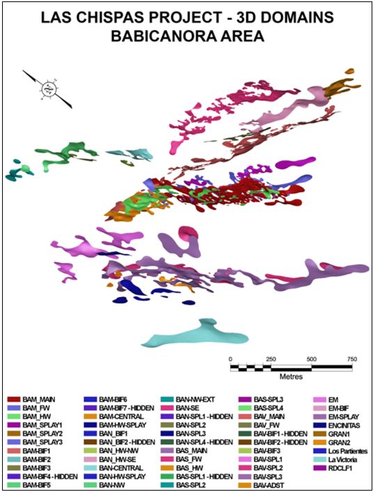
Source: P&E , 2025
| |
| Figure 11‑4: | Las Chispas 3D Domains |
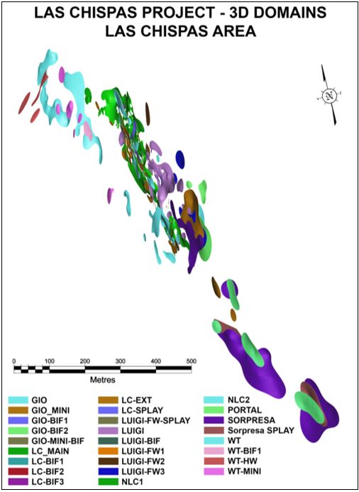
Source: P&E, 2025
| |
| 11.5 | Rock Code Determination |
A unique rock code was assigned to each wireframe and model blocks contained within each clipped vein in the Mineral Resource model, as presented in Table 11‑3. Material outside the “clipped” veins was treated as external waste and not considered in the Mineral Resource Estimate.
| Table 11‑3: | Rock Codes Used for the Mineral Resource Estimate |
| Area | Vein Group | Vein Name | Vein Code | Rock Code |
| Babicanora | Babi (BAM) | Babi Main | BAM Main | 1000 |
Babi Main RDCLF1 | BAM RDCLF1 | 1001 | ||
Babi Main Central | BAM CEN | 1002 | ||
Babi Main Bifurcation 1 | BAM BIF 1 | 1003 | ||
Babi Main Bifurcation 2 | BAM BIF 2 | 1004 | ||
Babi FW | BAM FW | 1005 | ||
Babi Main Bifurcation 3 | BAM BIF 3 | 1006 | ||
Babi Main Bifurcation 4 | BAM BIF 4 | 1007 | ||
Babi Main Bifurcation 5 | BAM BIF 5 | 1008 | ||
Babi Main Bifurcation 6 | BAM BIF 6 | 1009 | ||
Babi Main Bifurcation 7 | BAM BIF 7 | 1011 | ||
Babi HW | BAM HW | 1010 | ||
Babi Splay 1 | BAM Splay 1 | 1015 | ||
Babi Splay 2 | BAM Splay 2 | 1020 | ||
| El Muerto (EM) | El Muerto | EM | 1050 | |
El Muerto Bifurcation | EM BIF | 1055 | ||
El Muerto Splay | EM Splay | 1060 | ||
| Babi Norte (BAN) | Babi Norte SE | BAN SE | 1102 | |
Babi Norte NW | BAN NW | 1103 | ||
Babi Norte CEN | BAN CEN | 1104 | ||
Babi Norte HW SE | BAN HW SE | 1105 | ||
Babi Norte HW NW | BAN HW NW | 1106 | ||
| Babi Norte NW Extension | BAN NW EXT | 1107 | ||
Babi Norte HW Splay | BAN HW Splay | 1110 | ||
Babi Norte Bifurcation 2 | BAN BIF 2 | 1116 | ||
Babi Norte Splay 1 | BAN Splay 1 | 1130 | ||
Babi Norte Splay 2 | BAN Splay 2 | 1135 |
| |
| Area | Vein Group | Vein Name | Vein Code | Rock Code |
Babi Norte Splay 3 | BAN Splay 3 | 1140 | ||
Babi Norte Splay 4 | BAN Splay 4 | 1145 | ||
| Babi Sur (BAS) | Babi Sur Main | BAS Main | 1200 | |
Babi Sur FW | BAS FW | 1205 | ||
Babi Sur HW | BAS HW | 1210 | ||
Babi Sur Splay 1 | BAS Splay 1 | 1220 | ||
Babi Sur Splay 2 | BAS Splay 2 | 1221 | ||
Babi Sur Splay 3 | BAS Splay 3 | 1222 | ||
Babi Sur Splay 4 | BAS Splay 4 | 1223 | ||
| Granaditas (GRAN) | Granaditas 1 | GRAN 1 | 1300 | |
Granaditas 2 | GRAN 2 | 1305 | ||
| Babi Vista (BAV) | Babi Vista Main | BAV Main | 1400 | |
Babi Vista BIF 1 | BAV BIF 1 | 1401 | ||
Babi Vista BIF 2 | BAV BIF 2 | 1402 | ||
Babi Vista BIF 3 | BAV BIF 3 | 1403 | ||
Babi Vista Splay 1 | BAV Splay 1 | 1410 | ||
Babi Vista Splay 2 | BAV Splay 2 | 1415 | ||
Babi Vista Splay 3 | BAV Splay 3 | 1420 | ||
Babi Vista FW | BAV FW | 1450 | ||
Babi Vista Andesite | BAV AND | 1455 | ||
| Los Parientes | Los Parientes | LP | 1500 | |
| Encinitas | Encinitas | Encinitas | 1600 | |
| La Victoria | La Victoria | LV | 1700 | |
Las Chispas | Giovanni | Giovanni | GIO | 2001 |
Giovanni Mini | GIO_MINI | 2002 | ||
Giovanni Bifurcation 1 | GIO BIF 1 | 2004 | ||
Giovanni Bifurcation 2 | GIO BIF 2 | 2005 | ||
Giovanni Mini Bifurcation 1 | GIO Mini BIF 1 | 2006 | ||
| Las Chispas | Las Chispas Main | LC Main | 2003 | |
Las Chispas Bifurcation 1 | LC BIF 1 | 2007 | ||
Las Chispas Bifurcation 2 | LC BIF 2 | 2008 | ||
Las Chispas Bifurcation 3 | LC BIF 3 | 2009 | ||
Las Chispas Extension | LC EXT | 2010 |
| |
| Area | Vein Group | Vein Name | Vein Code | Rock Code |
Las Chispas Splay | LC Splay | 2011 | ||
North Las Chispas 01 | NLC 01 | 2012 | ||
North Las Chispas 02 | NLC 02 | 2013 | ||
| William Tell | William Tell | WT | 3001 | |
William Tell HW | WT_HW | 3002 | ||
William Tell Mini | WT_MINI | 3003 | ||
William Tell Bifurcation 1 | WT BIF 1 | 3004 | ||
| Luigi | Luigi | Luigi | 4001 | |
Luigi_FW 1 | Luigi_FW 1 | 4002 | ||
Luigi Bifurcation 1 | LUIGI BIF 1 | 4003 | ||
Luigi FW 2 | Luigi FW 2 | 4004 | ||
Luigi FW 3 | Luigi FW 3 | 4005 | ||
Luigi FW Splay | Luigi FW Splay | 4006 | ||
| Sorpresa | Sorpresa | Sorpresa | 5000 | |
Sorpresa Splay | Sorpresa Splay | 5001 | ||
Portal vein | Portal vein | 5002 |
| 11.6 | Wireframe Constrained Assays |
Wireframe constrained assays were back coded in the assay database with rock codes that were derived from intersections of the clipped mineralized solids and drill holes. The basic statistics of clipped mineralized wireframe constrained assays are presented in Table 11‑4.
| Table 11‑4: | Basic Statistics of All Assays Constrained Within Clipped Vein Wireframes |
Veins/Data type | Variable | Au | Ag | Length |
BAM Drill Holes | Number of Samples | 1,994 | 1,994 | 1,994 |
| Minimum Value * | 0.01 | 0.2 | 0.10 | |
| Maximum Value * | 1,115.00 | 33,380 | 3.10 | |
| Mean * | 9.64 | 888 | 0.72 | |
| Median * | 1.68 | 245 | 0.61 | |
| Geometric Mean * | 1.26 | 249 | 0.65 | |
| Variance | 1,466.99 | 5,014,962 | 0.12 | |
| Standard Deviation | 38.30 | 2,239 | 0.35 | |
| Coefficient of Variation | 3.97 | 2.52 | 0.49 |
| |
| Veins/Data type | Variable | Au | Ag | Length |
BAM UG Channel Samples | Number of Samples | 5,339 | 5,339 | 5,339 |
| Minimum Value * | 0.01 | 0.4 | 0.14 | |
| Maximum Value * | 1,438.00 | 66,738 | 2.59 | |
| Mean * | 13.18 | 1,121 | 0.62 | |
| Median * | 1.99 | 282 | 0.57 | |
| Geometric Mean * | 1.77 | 299 | 0.58 | |
| Variance | 1,936.56 | 9,218,250 | 0.06 | |
| Standard Deviation | 44.01 | 3,036 | 0.25 | |
| Coefficient of Variation | 3.34 | 2.71 | 0.39 | |
BAN Drill Holes | Number of Samples | 804 | 804 | 804 |
| Minimum Value * | 0.01 | 0.2 | 0.30 | |
| Maximum Value * | 1,045.00 | 66,552 | 2.38 | |
| Mean * | 16.02 | 1,899 | 0.57 | |
| Median * | 2.50 | 377 | 0.54 | |
| Geometric Mean * | 2.74 | 384 | 0.54 | |
| Variance | 3,356.99 | 29,455,130 | 0.04 | |
| Standard Deviation | 57.94 | 5,427 | 0.21 | |
| Coefficient of Variation | 3.62 | 2.86 | 0.36 | |
BAN Channel Samples | Number of Samples | 866 | 866 | 866 |
| Minimum Value * | 0.01 | 0.2 | 0.14 | |
| Maximum Value * | 1,498.00 | 140,330 | 2.79 | |
| Mean * | 23.72 | 3,162 | 0.57 | |
| Median * | 2.68 | 413 | 0.51 | |
| Geometric Mean * | 2.68 | 438 | 0.52 | |
| Variance | 6,406.51 | 92,739,266 | 0.08 | |
| Standard Deviation | 80.04 | 9,630 | 0.28 | |
| Coefficient of Variation | 3.37 | 3.05 | 0.48 | |
BAS Drill Holes | Number of Samples | 421 | 421 | 421 |
| Minimum Value * | 0.01 | 0.2 | 0.31 | |
| Maximum Value * | 167.00 | 7,311 | 2.51 | |
| Mean * | 7.27 | 376 | 0.72 | |
| Median * | 1.95 | 139 | 0.61 | |
| Geometric Mean * | 1.87 | 119 | 0.68 | |
| Variance | 366.63 | 626,183 | 0.08 | |
| Standard Deviation | 19.15 | 791 | 0.29 | |
| Coefficient of Variation | 2.63 | 2.10 | 0.40 |
| |
| Veins/Data type | Variable | Au | Ag | Length |
BAV Drill Holes | Number of Samples | 1,014 | 1,014 | 1,014 |
| Minimum Value * | 0.01 | 0.2 | 0.27 | |
| Maximum Value * | 3,366.00 | 114,814 | 2.44 | |
| Mean * | 26.88 | 2,118 | 0.53 | |
| Median * | 3.41 | 349 | 0.50 | |
| Geometric Mean * | 3.90 | 367.59 | 0.50 | |
| Variance | 17,451.70 | 47,506,086 | 0.04 | |
| Standard Deviation | 132.10 | 6,892 | 0.20 | |
| Coefficient of Variation | 4.91 | 3.25 | 0.39 | |
BAV Channel Samples | Number of Samples | 1,305 | 1,305 | 1,305 |
| Minimum Value * | 0.01 | 1 | 0.09 | |
| Maximum Value * | 1,707.00 | 140,270 | 1.63 | |
| Mean * | 45.79 | 4,167 | 0.56 | |
| Median * | 6.10 | 620 | 0.50 | |
| Geometric Mean * | 6.23 | 653 | 0.50 | |
| Variance | 17,067.97 | 108,178,900 | 0.07 | |
| Standard Deviation | 130.64 | 10,401 | 0.26 | |
| Coefficient of Variation | 2.85 | 2.50 | 0.47 | |
Drill Holes | Number of Samples | 61 | 61 | 61 |
| Minimum Value * | 0.05 | 1.5 | 0.49 | |
| Maximum Value * | 114.00 | 78,872 | 1.62 | |
| Mean * | 9.09 | 2,220 | 0.71 | |
| Median * | 2.14 | 274 | 0.59 | |
| Geometric Mean * | 2.32 | 288 | 0.67 | |
| Variance | 411.98 | 101,870,654 | 0.07 | |
| Standard Deviation | 20.30 | 10,093 | 0.27 | |
| Coefficient of Variation | 2.23 | 4.55 | 0.38 | |
EM Drill Holes | Number of Samples | 98 | 98 | 98 |
| Minimum Value * | 0.05 | 0.5 | 0.50 | |
| Maximum Value * | 21.80 | 2,178 | 2.06 | |
| Mean * | 3.96 | 303 | 0.86 | |
| Median * | 2.78 | 202 | 0.71 | |
| Geometric Mean * | 2.18 | 151 | 0.80 | |
| Variance | 15.38 | 121,857 | 0.14 | |
| Standard Deviation | 3.92 | 349 | 0.37 | |
| Coefficient of Variation | 0.99 | 1.15 | 0.43 |
| |
| Veins/Data type | Variable | Au | Ag | Length |
Los Parientes, Encinitas & La Victoria Drill Holes | Number of Samples | 37 | 37 | 37 |
| Minimum Value * | 0.42 | 0.2 | 0.50 | |
| Maximum Value * | 190.50 | 2,760 | 1.90 | |
| Mean * | 11.04 | 266 | 0.76 | |
| Median * | 2.56 | 86 | 0.60 | |
| Geometric Mean * | 3.54 | 54 | 0.70 | |
| Variance | 1,066.53 | 285,026 | 0.12 | |
| Standard Deviation | 32.66 | 534 | 0.35 | |
| Coefficient of Variation | 2.96 | 2.01 | 0.46 | |
Drill Holes | Number of Samples | 141 | 141 | 141 |
| Minimum Value * | 0.01 | 0.2 | 0.24 | |
| Maximum Value * | 316.00 | 26,540 | 2.00 | |
| Mean * | 7.30 | 829 | 0.63 | |
| Median * | 2.30 | 334 | 0.53 | |
| Geometric Mean * | 2.32 | 320 | 0.58 | |
| Variance | 774.13 | 5,536,438 | 0.09 | |
| Standard Deviation | 27.82 | 2,353 | 0.30 | |
| Coefficient of Variation | 3.81 | 2.84 | 0.47 | |
Giovanni UG Channel/Chip Samples | Number of Samples | 46 | 46 | N/A |
| Minimum Value * | 0.00 | 0.8 | N/A | |
| Maximum Value * | 33.30 | 8,340 | N/A | |
| Mean * | 1.99 | 333 | N/A | |
| Median * | 0.07 | 13 | N/A | |
| Geometric Mean * | 0.18 | 24 | N/A | |
| Variance | 31.45 | 1,550,019 | N/A | |
| Standard Deviation | 5.61 | 1,245 | N/A | |
| Coefficient of Variation | 2.82 | 3.74 | N/A |
| |
| Veins/Data type | Variable | Au | Ag | Length |
Las Chispas Drill Holes | Number of Samples | 261 | 261 | 261 |
| Minimum Value * | 0.01 | 0.2 | 0.30 | |
| Maximum Value * | 513.00 | 42,322 | 2.25 | |
| Mean * | 7.79 | 945 | 0.67 | |
| Median * | 1.51 | 231 | 0.58 | |
| Geometric Mean * | 1.15 | 154 | 0.63 | |
| Variance | 1,372.77 | 12,516,080 | 0.08 | |
| Standard Deviation | 37.05 | 3,538 | 0.28 | |
| Coefficient of Variation | 4.76 | 3.74 | 0.41 | |
Las Chispas UG Channel/Chip Samples | Number of Samples | 1,732 | 1,732 | N/A |
| Minimum Value * | 0.00 | 0.3 | N/A | |
| Maximum Value * | 136.00 | 10,000 | N/A | |
| Mean * | 2.24 | 341 | N/A | |
| Median * | 0.71 | 136 | N/A | |
| Geometric Mean * | 0.52 | 89 | N/A | |
| Variance | 31.22 | 411,873 | N/A | |
| Standard Deviation | 5.59 | 642 | N/A | |
| Coefficient of Variation | 2.49 | 1.88 | N/A | |
William Tell Drill Holes | Number of Samples | 60 | 60 | 60 |
| Minimum Value * | 0.01 | 0.2 | 0.35 | |
| Maximum Value * | 15.10 | 1,445 | 2.00 | |
| Mean * | 2.87 | 348 | 0.76 | |
| Median * | 1.93 | 253 | 0.59 | |
| Geometric Mean * | 1.16 | 156 | 0.71 | |
| Variance | 9.09 | 109,613 | 0.10 | |
| Standard Deviation | 3.02 | 331 | 0.31 | |
| Coefficient of Variation | 1.05 | 0.95 | 0.41 | |
William Tell UG Channel/Chip Samples | Number of Samples | 182 | 182 | N/A |
| Minimum Value * | 0.01 | 0.7 | N/A | |
| Maximum Value * | 52.20 | 2,730 | N/A | |
| Mean * | 2.94 | 249 | N/A | |
| Median * | 0.70 | 106 | N/A | |
| Geometric Mean * | 0.61 | 87 | N/A | |
| Variance | 35.53 | 166,934 | N/A | |
| Standard Deviation | 5.96 | 409 | N/A | |
| Coefficient of Variation | 2.03 | 1.64 | N/A |
| |
| Veins/Data type | Variable | Au | Ag | Length |
Luigi Drill Holes | Number of Samples | 124 | 124 | 124 |
| Minimum Value * | 0.05 | 0.3 | 0.25 | |
| Maximum Value * | 26.30 | 3,720 | 2.35 | |
| Mean * | 2.98 | 385 | 0.63 | |
| Median * | 1.44 | 214 | 0.55 | |
| Geometric Mean * | 1.32 | 167 | 0.58 | |
| Variance | 20.58 | 330,895 | 0.08 | |
| Standard Deviation | 4.54 | 575. | 0.29 | |
| Coefficient of Variation | 1.52 | 1.49 | 0.46 | |
Luigi UG Channel/Chip Samples | Number of Samples | 268 | 268 | N/A |
| Minimum Value * | 0.04 | 4.3 | N/A | |
| Maximum Value * | 22.90 | 3,990 | N/A | |
| Mean * | 1.75 | 296 | N/A | |
| Median * | 0.83 | 141 | N/A | |
| Geometric Mean * | 0.59 | 93 | N/A | |
| Variance | 8.93 | 279,699 | N/A | |
| Standard Deviation | 2.99 | 529 | N/A | |
| Coefficient of Variation | 1.70 | 1.79 | N/A | |
| Sorpresa | Number of Samples | 42 | 42 | 42 |
| Minimum Value * | 0.25 | 47 | 0.30 | |
| Maximum Value * | 24.90 | 4,220 | 0.99 | |
| Mean * | 3.12 | 536 | 0.57 | |
| Median * | 1.22 | 232 | 0.54 | |
| Geometric Mean * | 1.70 | 296 | 0.56 | |
| Variance | 21.04 | 630,017 | 0.02 | |
| Standard Deviation | 4.59 | 794 | 0.13 | |
| Coefficient of Variation | 1.47 | 1.48 | 0.23 |
Note: N/A = not applicable.
* Au & Ag units are g/t and length units are meters. Values are not weighted to sample length.
| 11.7 | Compositing and Capping |
Due to the nature of the narrow veins and in order to regularize the assay sampling intervals for grade interpolation, a 0.5 m compositing length was selected for the sample intervals that fell within the constraints of the above-mentioned vein wireframes. The composites were calculated for gold and silver over 0.5 m lengths, starting at the first point of intersection between assay data hole and hanging wall of the 3-D zonal constraint. The compositing process was halted on exit from the footwall of the 3-D wireframe constraint. Non-assayed intervals and below detection limit assays were set to 0.001 g/t gold and silver. If the last composite interval was <0.25 m, the composite length was adjusted to make all composite interval lengths of the vein intercept equal. This process would not introduce any short sample bias in the grade interpolation process. The constrained composite data were extracted to a point area file for grade capping analyses. The composite statistics of the clipped wireframes are summarized in Table 11‑5.
| |
| Table 11‑5: | Basic Statistics of Composites Constrained Within Clipped Vein Wireframes |
Vein Group (Data Type) | Variable | Au Composite | Au Cap | Ag Composite | Ag Cap | Length |
BAM Drill Holes | Number of Samples | 2,855 | 2,855 | 2,855 | 2,855 | 2,855 |
| Minimum Value * | 0.00 | 0.00 | 0 | 0 | 0.25 | |
| Maximum Value * | 981.34 | 270.40 | 27,168 | 15,598 | 0.75 | |
| Mean * | 8.23 | 7.66 | 754 | 728 | 0.50 | |
| Median * | 1.88 | 1.88 | 241 | 241 | 0.50 | |
| Variance | 877.84 | 418.63 | 2,964,087 | 2,437,692 | 0.00 | |
| Standard Deviation | 29.63 | 20.46 | 1722 | 1561 | 0.07 | |
| Coefficient of Variation | 3.60 | 2.67 | 2.28 | 2.15 | 0.14 | |
BAM Channel Samples | Number of Samples | 5,127 | 5,127 | 5,127 | 5,127 | 5,127 |
| Minimum Value * | 0.01 | 0.01 | 0.9 | 0.9 | 0.25 | |
| Maximum Value * | 1,438.00 | 98.74 | 66,738 | 11,913 | 0.74 | |
| Mean * | 12.31 | 10.13 | 1,084 | 958 | 0.50 | |
| Median * | 2.61 | 2.61 | 305.00 | 305.00 | 0.50 | |
| Variance | 1,722.38 | 358.69 | 8,650,898 | 3,374,352 | 0.00 | |
| Standard Deviation | 41.50 | 18.94 | 2,941 | 1,836 | 0.07 | |
| Coefficient of Variation | 3.37 | 1.87 | 2.71 | 1.92 | 0.14 | |
BAN Drill Holes | Number of Samples | 921 | 921 | 921 | 921 | 921 |
| Minimum Value* | 0.00 | 0.00 | 0 | 0 | 0.25 | |
| Maximum Value * | 713.61 | 330.50 | 51,257 | 35,604 | 0.74 | |
| Mean * | 15.04 | 13.78 | 1,797 | 1,711 | 0.50 | |
| Median * | 2.74 | 2.74 | 403 | 403 | 0.50 | |
| Variance | 2,208.29 | 1,304.59 | 21,535,965 | 15,556,677 | 0.01 | |
| Standard Deviation | 46.99 | 36.12 | 4,640 | 3,944 | 0.09 | |
| Coefficient of Variation | 3.12 | 2.62 | 2.58 | 2.30 | 0.19 | |
BAN Channel Samples | Number of Samples | 1,029 | 1,029 | 1,029 | 1,029 | 1,029 |
| Minimum Value* | 0.01 | 0.01 | 0.2 | 0.2 | 0.25 | |
| Maximum Value * | 1,468.06 | 162.40 | 140,330 | 39,625 | 0.74 | |
| Mean * | 21.67 | 17.24 | 2,976 | 2,712 | 0.48 | |
| Median * | 3.43 | 3.43 | 487 | 487 | 0.50 | |
| Variance | 4,525.74 | 1,153.23 | 71,091,055 | 36,852,878 | 0.01 | |
| Standard Deviation | 67.27 | 33.96 | 8,431 | 6,070 | 0.10 | |
| Coefficient of Variation | 3.10 | 1.97 | 2.83 | 2.24 | 0.21 |
| |
Vein Group (Data Type) | Variable | Au Composite | Au Cap | Ag Composite | Ag Cap | Length |
BAS Drill Holes | Number of Samples | 604 | 604 | 604 | 604 | 604 |
| Minimum Value * | 0.00 | 0.00 | 0 | 0 | 0.25 | |
| Maximum Value * | 155.60 | 110.50 | 7,310 | 3,280 | 0.74 | |
| Mean * | 7.57 | 6.80 | 332 | 315 | 0.51 | |
| Median * | 2.01 | 2.01 | 136 | 134 | 0.50 | |
| Variance | 375.27 | 246.21 | 468,917 | 341,373 | 0.00 | |
| Standard Deviation | 19.37 | 15.69 | 684 | 584 | 0.07 | |
| Coefficient of Variation | 2.56 | 2.31 | 2.06 | 1.85 | 0.13 | |
BAV Drill Holes | Number of Samples | 1,084 | 1,084 | 1,084 | 1,084 | 1,084 |
| Minimum Value * | 0.00 | 0.00 | 0 | 0. | 0.25 | |
| Maximum Value * | 2,775.91 | 366 | 94,867 | 32,741 | 0.75 | |
| Mean * | 25.67 | 20.86 | 1,948 | 1,776 | 0.50 | |
| Median * | 3.59 | 3.59 | 360 | 360 | 0.50 | |
| Variance | 12,658.30 | 2,538.50 | 32,722,746 | 18,320,711 | 0.01 | |
| Standard Deviation | 112.51 | 50.38 | 5,720 | 4,280 | 0.09 | |
| Coefficient of Variation | 4.38 | 2.42 | 2.94 | 2.41 | 0.19 | |
BAV Channel Samples | Number of Samples | 1,467 | 1,467 | 1,467 | 1,467 | 1,467 |
| Minimum Value * | 0.01 | 0.01 | 1 | 1 | 0.25 | |
| Maximum Value * | 1,600.35 | 377.20 | 88,490 | 39,643 | 0.74 | |
| Mean * | 36.65 | 32.63 | 3,429 | 3,202 | 0.48 | |
| Median * | 7.11 | 7.11 | 666 | 666 | 0.50 | |
| Variance | 8,826.24 | 4,488.95 | 58,903,491 | 42,995,539 | 0.01 | |
| Standard Deviation | 93.95 | 67.00 | 7,674 | 6,557 | 0.10 | |
| Coefficient of Variation | 2.56 | 2.05 | 2.24 | 2.05 | 0.21 | |
GRAN Drill Holes | Number of Samples | 85 | 85 | 85 | 85 | 85 |
| Minimum Value * | 0.05 | 0.05 | 1.5 | 1.5 | 0.25 | |
| Maximum Value * | 114.00 | 80.00 | 78,871 | 11,685 | 0.73 | |
| Mean * | 9.89 | 9.45 | 2,070 | 1,277 | 0.51 | |
| Median * | 2.54 | 2.54 | 269 | 269 | 0.50 | |
| Variance | 403.33 | 333.52 | 76,063,208 | 7,136,209 | 0.01 | |
| Standard Deviation | 20.08 | 18.26 | 8,721. | 2,671 | 0.08 | |
| Coefficient of Variation | 2.03 | 1.93 | 4.21 | 2.09 | 0.16 |
| |
Vein Group (Data Type) | Variable | Au Composite | Au Cap | Ag Composite | Ag Cap | Length |
EM Drill Holes | Number of Samples | 166 | 166 | 166 | 166 | 166 |
| Minimum Value * | 0.05 | 0.05 | 0.5 | 0.5 | 0.25 | |
| Maximum Value * | 21.80 | 15.17 | 2,177 | 2,048 | 0.71 | |
| Mean * | 3.80 | 3.69 | 281 | 279 | 0.50 | |
| Median * | 2.75 | 2.75 | 195 | 195 | 0.50 | |
| Variance | 12.57 | 10.03 | 108,740 | 103,583 | 0.01 | |
| Standard Deviation | 3.55 | 3.17 | 329 | 321 | 0.07 | |
| Coefficient of Variation | 0.93 | 0.86 | 1.17 | 1.15 | 0.14 | |
Los Parientes, Encinitas and La Victoria Drill Holes | Number of Samples | 54 | 54 | 54 | 54 | 54 |
| Minimum Value * | 0.42 | 0.42 | 0.2 | 0.2 | 0.27 | |
| Maximum Value * | 190.50 | 74.93 | 2,759 | 1,027 | 0.74 | |
| Mean * | 8.54 | 6.11 | 200 | 152 | 0.52 | |
| Median * | 2.56 | 2.56 | 61 | 61 | 0.52 | |
| Variance | 746.14 | 188.93 | 206,212 | 58,281 | 0.01 | |
| Standard Deviation | 27.32 | 13.75 | 454 | 241 | 0.09 | |
| Coefficient of Variation | 3.20 | 2.25 | 2.27 | 1.58 | 0.18 | |
Giovanni Drill Holes | Number of Samples | 178 | 178 | 178 | 178 | 178 |
| Minimum Value * | 0.00 | 0.00 | 0.0 | 0.0 | 0.25 | |
| Maximum Value * | 316.00 | 55.60 | 26,539 | 7,240 | 0.73 | |
| Mean * | 6.73 | 4.98 | 757 | 641 | 0.49 | |
| Median * | 2.30 | 2.30 | 337 | 332 | 0.50 | |
| Variance | 629.02 | 70.64 | 4,420,769 | 890,228 | 0.01 | |
| Standard Deviation | 25.08 | 8.40 | 2,102 | 943 | 0.09 | |
| Coefficient of Variation | 3.73 | 1.69 | 2.78 | 1.47 | 0.18 | |
Giovanni UG Channel/ Chip Samples | Number of Samples | 19.00 | 19.00 | 19.00 | 19.00 | N/A |
| Minimum Value * | 0.05 | 0.05 | 5 | 5. | N/A | |
| Maximum Value * | 33.30 | 33.30 | 8,340 | 8,340 | N/A | |
| Mean * | 5.44 | 5.44 | 849 | 849 | N/A | |
| Median * | 3.41 | 3.41 | 594 | 594 | N/A | |
| Variance | 56.19 | 56.19 | 3,264,505 | 3,264,505 | N/A | |
| Standard Deviation | 7.50 | 7.50 | 1,806 | 1,806 | N/A | |
| Coefficient of Variation | 1.38 | 1.38 | 2.13 | 2.13 | N/A |
| |
Vein Group (Data Type) | Variable | Au Composite | Au Cap | Ag Composite | Ag Cap | Length |
Las Chispas Drill Holes | Number of Samples | 319 | 319 | 319 | 319 | 319 |
| Minimum Value * | 0.00 | 0.0 | 0 | 0 | 0.25 | |
| Maximum Value * | 464.86 | 245.00 | 38,954 | 13,560 | 0.74 | |
| Mean * | 7.69 | 6.92 | 934 | 774 | 0.50 | |
| Median * | 1.63 | 1.63 | 256 | 256 | 0.50 | |
| Variance | 1,035.77 | 554.75 | 9,828,187 | 3,200,889 | 0.01 | |
| Standard Deviation | 32.18 | 23.55 | 3,134 | 1,789 | 0.07 | |
| Coefficient of Variation | 4.19 | 3.40 | 3.36 | 2.31 | 0.15 | |
Las Chispas UG Channel/ Chip Samples | Number of Samples | 954 | 954 | 954 | 954 | N/A |
| Minimum Value * | 0.01 | 0.01 | 0.3 | 0.3 | N/A | |
| Maximum Value * | 136.00 | 46.50 | 10,000 | 5,770 | N/A | |
| Mean * | 3.05 | 2.94 | 468 | 464 | N/A | |
| Median * | 1.18 | 1.18 | 228 | 228 | N/A | |
| Variance | 45.20 | 27.70 | 547,458 | 481,670 | N/A | |
| Standard Deviation | 6.72 | 5.26 | 739 | 694 | N/A | |
| Coefficient of Variation | 2.21 | 1.79 | 1.58 | 1.50 | N/A | |
William Tell Drill Holes | Number of Samples | 88 | 88 | 88 | 88 | 88 |
| Minimum Value * | 0.00 | 0.00 | 0 | 0 | 0.35 | |
| Maximum Value * | 15.10 | 8.77 | 1,445 | 1,370 | 0.72 | |
| Mean * | 2.67 | 2.50 | 335 | 326 | 0.52 | |
| Median * | 1.93 | 1.93 | 245 | 241 | 0.50 | |
| Variance | 7.62 | 5.17 | 103,538 | 98,792 | 0.00 | |
| Standard Deviation | 2.76 | 2.27 | 321 | 314 | 0.06 | |
| Coefficient of Variation | 1.03 | 0.91 | 0.96 | 0.96 | 0.11 | |
William Tell UG Channel/ Chip Samples | Number of samples | 132 | 132 | 132 | 132 | N/A |
| Minimum Value * | 0.01 | 0.01 | 1 | 1 | N/A | |
| Maximum Value * | 52.20 | 32.50 | 2,730 | 2,170 | N/A | |
| Mean * | 3.60 | 3.45 | 315 | 311 | N/A | |
| Median * | 1.42 | 1.42 | 170 | 170 | N/A | |
| Variance | 42.55 | 30.97 | 207,318 | 189,187 | N/A | |
| Standard Deviation | 6.52 | 5.56 | 455 | 434 | N/A | |
| Coefficient of Variation | 1.81 | 1.61 | 1.44 | 1.40 | N/A | |
Luigi Drill Holes | Number of Samples | 160 | 160 | 160 | 160 | 160 |
| Minimum Value * | 0.05 | 0.05 | 0.3 | 0.3 | 0.25 | |
| Maximum Value * | 26.30 | 23.90 | 3,720 | 3,280 | 0.72 | |
| Mean * | 2.98 | 2.80 | 385 | 370 | 0.49 | |
| Median * | 1.48 | 1.48 | 222 | 222 | 0.50 | |
| Variance | 20.34 | 17.79 | 325,871 | 296,997 | 0.01 | |
| Standard Deviation | 4.51 | 4.22 | 570 | 544 | 0.08 | |
| Coefficient of Variation | 1.51 | 1.51 | 1.48 | 1.47 | 0.17 |
| |
Vein Group (Data Type) | Variable | Au Composite | Au Cap | Ag Composite | Ag Cap | Length |
Luigi UG Channel/ Chip Samples | Number of samples | 166 | 166 | 166 | 166 | N/A |
| Minimum Value * | 0.05 | 0.05 | 5 | 5 | N/A | |
| Maximum Value * | 22.90 | 18.90 | 3,990 | 3,130 | N/A | |
| Mean * | 2.40 | 2.37 | 412. | 403 | N/A | |
| Median * | 1.24 | 1.24 | 210 | 210 | N/A | |
| Variance | 12.18 | 11.05 | 387,499 | 327,272 | N/A | |
| Standard Deviation | 3.49 | 3.32 | 622 | 572 | N/A | |
| Coefficient of Variation | 1.45 | 1.40 | 1.51 | 1.42 | N/A | |
Sorpresa and Portal Drill Holes | Number of Samples | 46 | 46 | 46 | 46 | 46 |
| Minimum Value * | 0.40 | 0.40 | 83 | 83 | 0.25 | |
| Maximum Value * | 24.90 | 18.52 | 4,219 | 3,221 | 0.72 | |
| Mean * | 3.40 | 3.04 | 573 | 522 | 0.52 | |
| Median * | 1.22 | 1.18 | 231 | 227 | 0.51 | |
| Variance | 24.75 | 17.15 | 737,079 | 529,234 | 0.01 | |
| Standard Deviation | 4.97 | 4.14 | 858 | 727 | 0.10 | |
| Coefficient of Variation | 1.47 | 1.36 | 1.50 | 1.39 | 0.20 | |
Sorpresa UG Channel/ Chip Samples | Number of Samples | 12 | 12 | 12 | 12 | N/A |
| Minimum Value * | 0.20 | 0.20 | 66 | 66 | N/A | |
| Maximum Value * | 5.94 | 5.94 | 1,847 | 1,847 | N/A | |
| Mean * | 2.57 | 2.57 | 776 | 776 | N/A | |
| Median * | 1.97 | 1.97 | 644 | 644 | N/A | |
| Variance | 4.56 | 4.56 | 421,462 | 421,462 | N/A | |
| Standard Deviation | 2.14 | 2.14 | 649 | 649 | N/A | |
| Coefficient of Variation | 0.83 | 0.83 | 0.84 | 0.84 | N/A |
Note: N/A = not applicable. * Au & Ag units are g/t and length units are meters.
UG channel/chip samples in Las Chispas area include operation channel samples.
| 11.8 | Capping Strategy |
Grade capping and high-grade transition analyses were undertaken on the 0.5 m composite values in the database within the constraining wireframes to control possible bias resulting from erratic high-grade composites in the database, and to maintain the high-grade local variation. The high-grade transition consists of a restrictive search ellipse and a secondary lower maximum composite value used for interpolation at distances beyond the restrictive search ellipse.
| |
Log-probability plots for gold and silver composites were generated by Las Chispas Operations for each mineralized vein. The drill hole and channel sample composites were analyzed separately for each vein. The QPs of this Technical Report Summary section reviewed and agreed with the capping and high-grade transition methods and selected values.
The capped composite statistics are summarized in Table 11‑5. The grade capping and high-grade transition values for gold and silver are presented in Table 11‑6 and Table 11‑7, respectively. The capped composites were utilized to develop variograms and for block model grade interpolation and classification.
| |
| Table 11‑6: | Gold Grade Capping |
| Vein _ Data Type | Maximum Uncapped Value (Au g/t) | Cap (Au g/t) | Number Samples Capped | Cap Percentile (%) | High Grade Transition Value (Au g/t) | Number Samples for High Grade Transition | High Grade Transition Percentile (%) |
| 981.3 | 270.4 | 4 | 99.8 | 199.30 | 4 | 99.8 | |
| BAM_Main_CH | 1,438 | 98.7 | 83 | 98.3 | none | 0 | 100.0 |
| BAM_Central_DH | 104 | 29.45 | 1 | 99.8 | 16.81 | 7 | 98.6 |
| BAM_Central_CH | 88.4 | none | 0 | 100.0 | none | 0 | 100.0 |
| BAM_FW_DH | 477.1 | 179.7 | 5 | 99.6 | none | 0 | 100.0 |
| BAM_FW_CH | 675.0 | 40.0 | 26 | 97.2 | none | 0 | 100.0 |
| BAM_HW_DH | 91.5 | 16.25 | 5 | 99.5 | none | 0 | 100.0 |
| BAM_HW_CH | 43.2 | none | 0 | 100.0 | none | 0 | 100.0 |
| BAM_BIF 1_DH | 85.3 | 40 | 1 | 99.6 | none | 0 | 100.0 |
| BAM_BIF 1_CH | 15.1 | none | 0 | 100.0 | none | 0 | 100.0 |
| BAM_BIF 2_DH | 76.64 | 69.92 | 2 | 98.7 | none | 0 | 100.0 |
| BAM_BIF 2_CH | 16.01 | none | 0 | 100.0 | none | 0 | 100.0 |
| BAM BIF 3_DH | 20.4 | 18.52 | 2 | 97.5 | none | 0 | 100.0 |
| BAM BIF 3_CH | 27.2 | 20.00 | 1 | 98.1 | none | 0 | 100.0 |
| BAM BIF 4_DH | 51.3 | none | 0 | 100.0 | none | 0 | 100.0 |
| BAM BIF 4_CH | 4.68 | none | 0 | 100.0 | none | 0 | 100.0 |
| BAM BIF 5_DH | 9.74 | 7.59 | 1 | 99.5 | none | 0 | 100.0 |
| BAM BIF 5_CH | 42.8 | none | 0 | 100.0 | none | 0 | 100.0 |
| BAM BIF 6_DH | 37 | 12.53 | 3 | 98.3 | none | 0 | 100.0 |
| BAM BIF 6_CH | 62.80 | none | 0 | 100.0 | none | 0 | 100.0 |
| BAM BIF 7_DH | 1.23 | none | 0 | 100.0 | none | 0 | 100.0 |
| |
| Vein _ Data Type | Maximum Uncapped Value (Au g/t) | Cap (Au g/t) | Number Samples Capped | Cap Percentile (%) | High Grade Transition Value (Au g/t) | Number Samples for High Grade Transition | High Grade Transition Percentile (%) |
| BAM BIF 7_CH | 14.80 | none | 0 | 100.0 | none | 0 | 100.0 |
| BAM_Splay 1_DH | 4.02 | none | 0 | 100.0 | none | 0 | 100.0 |
| BAM_Splay 2_DH | 4.66 | 4.24 | 2 | 99.1 | none | 0 | 100.0 |
| BAM_Splay 2_CH | 6.45 | none | 0 | 100.0 | none | 0 | 100.0 |
| BAM RDCLF1_DH | 83.06 | 31.53 | 1 | 99.5 | none | 0 | 100.0 |
| BAM RDCLF1_CH | 312.0 | 120.3 | 3 | 98.9 | none | 0 | 100.0 |
| EM_DH | 18.1 | 9.58 | 4 | 98.7 | 8.49 | 6 | 98 |
| EM_BIF_DH | 3.63 | 3.38 | 2 | 92.9 | none | 0 | 100.0 |
| EM_SPLAY_DH | 21.8 | 15.17 | 1 | 99.4 | 12.22 | 3 | 98.2 |
| LOS_PARIENTES_DH | 19.95 | 11.07 | 2 | 95.8 | none | 0 | 100.0 |
| BAN_BIF 2_DH | 0.73 | none | 0 | 100.0 | none | 0 | 100.0 |
| BAN_BIF 2_CH | 16.06 | none | 0 | 100.0 | none | 0 | 100.0 |
| BAN_HW_NW_DH | 14.9 | 4.95 | 1 | 99.2 | none | 0 | 100.0 |
| BAN_HW_SE_DH | 20.0 | 16.25 | 3 | 98.6 | 12.00 | 6 | 97.1 |
| BAN_HW_SE_CH | 3.72 | none | 0 | 100.0 | none | 0 | 100.0 |
| BAN_HW Splay_DH | 30.0 | 10.1 | 2 | 97.9 | none | 0 | 100.0 |
| BAN Main CEN_DH | 305 | 71.8 | 2 | 97.0 | 24.85 | 3 | 95.5 |
| BAN Main NW_DH | 66.9 | 31.9 | 1 | 99.4 | 17.59 | 7 | 95.5 |
| BAN Main SE_DH | 713.6 | 330.5 | 4 | 99.6 | 240.20 | 5 | 99.5 |
| BAN Main SE_CH | 1,468 | 162.4 | 27 | 98.1 | none | 0 | 100.0 |
| BAN NW EXT_DH | 27.4 | 24.14 | 1 | 98.2 | none | 0 | 100.0 |
| BAN_Splay 1_DH | 9.22 | 8.04 | 1 | 97.7 | 6.86 | 1 | 97.7 |
| BAN_Splay 2_DH | 109 | 18.72 | 3 | 99.5 | 16.00 | 4 | 99.3 |
| |
| Vein _ Data Type | Maximum Uncapped Value (Au g/t) | Cap (Au g/t) | Number Samples Capped | Cap Percentile (%) | High Grade Transition Value (Au g/t) | Number Samples for High Grade Transition | High Grade Transition Percentile (%) |
| BAN_Splay 2_CH | 95.82 | 15.84 | 8 | 97.2 | none | 0 | 100.0 |
| BAN_Splay 3_DH | 105 | 87.03 | 2 | 98.9 | 70.40 | 2 | 98.9 |
| BAN_Splay 3_CH | 40.31 | none | 0 | 100.0 | none | 0 | 100.0 |
| BAN_Splay 4_DH | 13.75 | 8.22 | 1 | 99.4 | 6.00 | 1 | 99.4 |
| BAN_Splay 4_CH | 2.59 | none | 0 | 100.0 | none | 0 | 100.0 |
| BAV_Main_DH | 2,776 | 366 | 6 | 99.6 | 265.70 | 13 | 99.1 |
| BAV_Main_CH | 1,600 | 377 | 22 | 98.8 | none | 0 | 100.0 |
| BAV_FW_DH | 143 | 67.91 | 1 | 99.4 | 57.99 | 3 | 98.2 |
| BAV_FW_CH | 274 | 120.0 | 2 | 97.9 | none | 0 | 100.0 |
| BAV_Andesite_DH | 124.5 | 118.6 | 2 | 92.3 | 38.61 | 2 | 92.3 |
| BAV_BIF 1_DH | 6.66 | 4.87 | 2 | 99.3 | 4.30 | 2 | 98.3 |
| BAV_BIF 1_CH | 19.00 | none | 0 | 100.0 | none | 0 | 100.0 |
| BAV_BIF 2_DH | 129.8 | 43.27 | 3 | 99.5 | 19.77 | 4 | 99.3 |
| BAV_BIF 2_CH | 631 | 11.8 | 21 | 95.4 | none | 0 | 100.0 |
| BAV_BIF 3_CH | 106 | none | 0 | 100.0 | none | 0 | 100.0 |
| BAV_Splay 1_DH | 49.9 | 8.43 | 4 | 96.7 | 7.09 | 2 | 98.2 |
| BAV_Splay 2_DH | 124 | 34.47 | 1 | 99.3 | 19.85 | 3 | 97.8 |
| BAV_Splay 3_DH | 12.6 | 8.24 | 1 | 99.3 | 5.15 | 2 | 98.6 |
| GRAN_1_DH | 114 | 80 | 1 | 99.3 | 53.56 | 5 | 96.2 |
| GRAN_2_DH | 10.05 | 8.2 | 4 | 95.8 | none | 0 | 100.0 |
| BAS_Main | 155.6 | 110.5 | 6 | 99.2 | 48.90 | 12 | 98.3 |
| BAS_HW | 61.8 | 18.9 | 3 | 99.3 | none | 0 | 100.0 |
| BAS_FW | 119 | 18.7 | 2 | 99.5 | none | 0 | 100.0 |
| |
| Vein _ Data Type | Maximum Uncapped Value (Au g/t) | Cap (Au g/t) | Number Samples Capped | Cap Percentile (%) | High Grade Transition Value (Au g/t) | Number Samples for High Grade Transition | High Grade Transition Percentile (%) |
| BAS_Splay 1 | 5.69 | 4.1 | 1 | 99.4 | 3.81 | 1 | 99.4 |
| BAS_Splay 2 | 6.25 | 5.9 | 1 | 99.4 | 5.72 | 1 | 99.4 |
| BAS_Splay 3 | 3.44 | 3.39 | 2 | 98.8 | 3.10 | 3 | 98.2 |
| BAS_Splay 4 | 4.29 | none | 0 | 100.0 | none | 0 | 100.0 |
| Encinitas | 190.5 | 74.93 | 2 | 99.2 | 12.11 | 2 | 99.2 |
| La Victoria | 3.65 | none | 0 | 100.0 | none | 0 | 100.0 |
| Giovanni_CH | 2.08 | none | 0 | 100.0 | none | 0 | 100.0 |
| Giovanni_DH | 316 | 48.6 | 1 | 99.8 | 14.56 | 5 | 98.8 |
| Gio BIF 1_DH | 5.62 | 2.3 | 2 | 97.2 | none | 0 | 100.0 |
| Gio BIF 2_DH | 14.4 | none | 0 | 100.0 | none | 0 | 100.0 |
| Gio Mini_CH | 15.2 | none | 0 | 100.0 | none | 0 | 100.0 |
| Gio Mini_DH | 92.6 | 55.6 | 2 | 99.5 | 15.85 | 5 | 98.8 |
| Gio Mini BIF 1_DH | 2.59 | 2.15 | 2 | 98.3 | none | 0 | 100.0 |
| Las Chispas_CH | 136 | 46.5 | 2 | 99.9 | 42.20 | 6 | 99.6 |
| Las Chispas_DH | 464.86 | 245 | 1 | 99.8 | 76.76 | 6 | 98.9 |
| Las Chispas BIF 1_DH | 12 | none | 0 | 100.0 | none | 0 | 100.0 |
| Las Chispas BIF 2_DH | 10.52 | 8.79 | 2 | 94.6 | none | 0 | 100.0 |
| Las Chispas BIF 3_DH | 7.13 | 6.19 | 1 | 98.9 | none | 0 | 100.0 |
| Las Chispas Ext_DH | 31.5 | 9.51 | 1 | 98.3 | 3.71 | 2 | 96.6 |
| Las Chispas Splay_CH | 9.82 | none | 0 | 100.0 | none | 0 | 100.0 |
| Las Chispas Splay_DH | 23.90 | 23.90 | 2 | 98.1 | none | 0 | 100.0 |
| Luigi_CH | 22.9 | 18.9 | 2 | 99.2 | 14.00 | 3 | 98.9 |
| Luigi_DH | 26.3 | 23.9 | 2 | 99.5 | 17.43 | 4 | 99.0 |
| |
| Vein _ Data Type | Maximum Uncapped Value (Au g/t) | Cap (Au g/t) | Number Samples Capped | Cap Percentile (%) | High Grade Transition Value (Au g/t) | Number Samples for High Grade Transition | High Grade Transition Percentile (%) |
| Luigi BIF 1_DH | 5.64 | 3.32 | 1 | 98.9 | none | 0 | 100.0 |
| Luigi FW 1_DH | 9.20 | 2.89 | 2 | 98.2 | none | 0 | 100.0 |
| Luigi FW 2_DH | 7.69 | 4.59 | 2 | 97.7 | none | 0 | 100.0 |
| Luigi FW 3_DH | 15.35 | 6.87 | 1 | 99.5 | none | 0 | 100.0 |
| Luigi FW Splay_DH | 5.11 | 3.90 | 2 | 96.0 | none | 0 | 100.0 |
| NLC 01_DH | 39.20 | none | 0 | 100.0 | none | 0 | 100.0 |
| NLC 02_DH | 1.44 | none | 0 | 100.0 | none | 0 | 100.0 |
| Portal Vein_DH | 24.90 | 18.52 | 1 | 99.1 | none | 0 | 100.0 |
| Sorpresa_DH | 15.80 | 9.87 | 1 | 99.3 | 5.90 | 5 | 96.4 |
| Sorpresa Splay_DH | 5.25 | 1.06 | 1 | 96.9 | none | 0 | 100.0 |
| William Tell_CH | 52.20 | 32.50 | 1 | 99.4 | 11.15 | 10 | 94.3 |
| William Tell_DH | 15.10 | 7.93 | 1 | 99.8 | 6.65 | 5 | 98.8 |
| William Tell BIF 1_DH | 3.58 | 3.00 | 2 | 96.4 | none | 0 | 100.0 |
| William Tell HW_DH | 6.57 | 5.65 | 4 | 94.7 | none | 0 | 100.0 |
| William Tell Mini_DH | 13.10 | 8.77 | 3 | 98.2 | none | 0 | 100.0 |
Note: CH=Channel, DH=Drill Hole.
| |
| Table 11‑7: | Silver Grade Capping |
| Vein _ Data Type | Maximum Uncapped Value (Ag g/t) | Cap (Ag g/t) | Number Samples Capped | Cap Percentile (%) | High Grade Transition Value (Ag g/t) | Number Samples for High Grade Transition | High Grade Transition Percentile (%) |
| BAM_Main_DH | 27,168 | 15,598 | 3 | 99.8 | 12,996 | 7 | 99.6 |
| BAM_Main_CH | 66,738 | 11,913 | 42 | 99.1 | none | 0 | 100.0 |
| BAM_Central_DH | 2,560 | 2,149 | 4 | 99.2 | 1,764 | 7 | 98.6 |
| BAM_Central_CH | 3,430 | none | 0 | 100.0 | none | 0 | 100.0 |
| BAM_FW_DH | 21,858 | 14,139 | 6 | 99.5 | none | 0 | 100.0 |
| BAM_FW_CH | 46,600 | 5,000 | 26 | 97.2 | none | 0 | 100.0 |
| BAM_HW_DH | 3,916 | 1,034 | 12 | 98.8 | none | 0 | 100.0 |
| BAM_HW_CH | 4,340 | 3,900 | 1 | 99.4 | none | 0 | 100.0 |
| BAM_BIF 1_DH | 9,990 | 5,004 | 1 | 99.6 | none | 0 | 100.0 |
| BAM_BIF 1_CH | 1,829 | none | 0 | 100.0 | none | 0 | 100.0 |
| BAM_BIF 2_DH | 12,100 | 7,015 | 2 | 98.7 | none | 0 | 100.0 |
| BAM_BIF 2_CH | 2,446 | none | 0 | 100.0 | none | 0 | 100.0 |
| BAM BIF 3_DH | 3,210 | 1,708 | 1 | 98.8 | none | 0 | 100.0 |
| BAM BIF 3_CH | 2,770 | 2,511 | 1 | 98.1 | none | 0 | 100.0 |
| BAM BIF 4_DH | 4,180 | none | 0 | 100.0 | none | 0 | 100.0 |
| BAM BIF 4_CH | 460 | none | 0 | 100.0 | none | 0 | 100.0 |
| BAM BIF 5_DH | 1,275 | 951.9 | 1 | 99.5 | none | 0 | 100.0 |
| BAM BIF 5_CH | 5,068 | 5,000 | 1 | 98.3 | none | 0 | 100.0 |
| BAM BIF 6_DH | 5,882 | 1,154 | 2 | 98.9 | none | 0 | 100.0 |
| BAM BIF 6_CH | 4,601 | 3,455.0 | 1 | 99.4 | none | 0 | 100.0 |
| BAM BIF 7_DH | 120 | 76.2 | 1 | 98.8 | none | 0 | 100.0 |
| BAM BIF 7_CH | 1,426 | none | 0 | 100.0 | none | 0 | 100.0 |
| |
| Vein _ Data Type | Maximum Uncapped Value (Ag g/t) | Cap (Ag g/t) | Number Samples Capped | Cap Percentile (%) | High Grade Transition Value (Ag g/t) | Number Samples for High Grade Transition | High Grade Transition Percentile (%) |
| BAM_Splay 1_DH | 527 | 475 | 2 | 96.3 | none | 0 | 100.0 |
| BAM_Splay 2_DH | 559 | 433.2 | 2 | 99.1 | none | 0 | 100.0 |
| BAM_Splay 2_CH | 320.00 | none | 0 | 100.0 | none | 0 | 100.0 |
| BAM RDCLF1_DH | 14,604 | 3,518 | 1 | 99.5 | none | 0 | 100.0 |
| BAM RDCLF1_CH | 56,640 | 41,484 | 2 | 99.3 | none | 0 | 100.0 |
| EM_DH | 952 | 769.8 | 4 | 98.7 | 607 | 5 | 98.4 |
| EM_BIF_DH | 311 | 279.4 | 1 | 96.4 | none | 0 | 100.0 |
| EM_SPLAY_DH | 2,178 | 2,048 | 2 | 98.8 | 1,868 | 3 | 98.2 |
| LOS_PARIENTES_DH | 1,800 | 954.7 | 2 | 95.8 | none | 0 | 100.0 |
| BAN_BIF 2_DH | 92 | none | 0 | 100.0 | none | 0 | 100.0 |
| BAN_BIF 2_CH | 1,625 | none | 0 | 100.0 | none | 0 | 100.0 |
| BAN_HW_NW_DH | 938.4 | 800 | 1 | 99.2 | none | 0 | 100.0 |
| BAN_HW_SE_DH | 5,039 | 4,532 | 1 | 99.5 | 1,626 | 4 | 98.1 |
| BAN_HW_SE_CH | 329 | none | 0 | 100.0 | none | 0 | 100.0 |
| BAN_HW Splay_DH | 5,457 | 1,902 | 2 | 97.9 | none | 0 | 100.0 |
| BAN Main CEN_DH | 13,890 | 6,330 | 1 | 98.5 | 2,790 | 2 | 97.0 |
| BAN Main NW_DH | 6,950 | 2,840 | 1 | 99.4 | 2,491 | 4 | 97.4 |
| BAN Main SE_DH | 51,257 | 35,604 | 4 | 99.6 | 24,641 | 6 | 99.4 |
| BAN Main SE_CH | 140,330 | 39,625 | 9 | 99.4 | none | 0 | 100.0 |
| BAN NW EXT_DH | 3,300 | 3,031 | 1 | 98.2 | none | 0 | 100.0 |
| BAN_Splay 1_DH | 1,040 | 896.7 | 1 | 97.7 | 738 | 1 | 97.7 |
| BAN_Splay 2_DH | 8,340 | 2,406 | 4 | 99.4 | 1,455 | 6 | 98.9 |
| BAN_Splay 2_CH | 7,476 | 1,584 | 10 | 96.5 | none | 0 | 100.0 |
| |
| Vein _ Data Type | Maximum Uncapped Value (Ag g/t) | Cap (Ag g/t) | Number Samples Capped | Cap Percentile (%) | High Grade Transition Value (Ag g/t) | Number Samples for High Grade Transition | High Grade Transition Percentile (%) |
| BAN_Splay 3_DH | 9,630 | 8,053 | 1 | 99.4 | 6,476 | 2 | 98.9 |
| BAN_Splay 3_CH | 6,619 | none | 0 | 100.0 | none | 0 | 100.0 |
| BAN_Splay 4_DH | 1,065 | 1,085 | 1 | 99.4 | 1,051 | 1 | 99.4 |
| BAN_Splay 4_CH | 219.0 | none | 0 | 100.0 | none | 0 | 100.0 |
| BAV_Main_DH | 94,867 | 32,741 | 7 | 99.5 | 20,298 | 16 | 98.9 |
| BAV_Main_CH | 88,490 | 39,643 | 14 | 99.2 | none | 0 | 100.0 |
| BAV_FW_DH | 8,933 | 6,631 | 3 | 98.2 | 3,545 | 5 | 97.1 |
| BAV_FW_CH | 11,492 | 9,303 | 2 | 97.9 | none | 0 | 100.0 |
| BAV_Andesite_DH | 86 | 84.92 | 2 | 92.3 | 45.16 | 2 | 92.3 |
| BAV_BIF 1_DH | 1,039 | 427.4 | 2 | 99.3 | 415 | 2 | 98.3 |
| BAV_BIF 1_CH | 2,275 | none | 0 | 100.0 | none | 0 | 100.0 |
| BAV_BIF 2_DH | 11,950 | 4,926 | 4 | 99.3 | 888.8 | 8 | 98.6 |
| BAV_BIF 2_CH | 34,810 | 920 | 23 | 95.0 | none | 0 | 100.0 |
| BAV_BIF 3_CH | 12,700 | none | 0 | 100.0 | none | 0 | 100.0 |
| BAV_Splay 1_DH | 6,917 | 935.9 | 4 | 96.7 | 893.1 | 1 | 99.1 |
| BAV_Splay 2_DH | 6,930 | 4,292 | 1 | 99.3 | 3,301 | 3 | 97.8 |
| BAV_Splay 3_DH | 1,798 | 1,749 | 1 | 99.3 | 705.4 | 2 | 98.6 |
| GRAN_1_DH | 78,871 | 11,685 | 1 | 99.3 | 6,910 | 5 | 96.2 |
| GRAN_2_DH | 677 | 520 | 2 | 97.9 | none | 0 | 100.0 |
| BAS_Main | 7,311 | 3,280 | 7 | 99.1 | 2,843 | 12 | 98.3 |
| BAS_HW | 138 | 80.9 | 2 | 99.5 | none | 0 | 100.0 |
| BAS_FW | 1,115 | 898 | 2 | 99.5 | 598.6 | 5 | 98.6 |
| BAS_Splay 1 | 609 | 300.9 | 1 | 99.4 | 211 | 2 | 98.9 |
| |
| Vein _ Data Type | Maximum Uncapped Value (Ag g/t) | Cap (Ag g/t) | Number Samples Capped | Cap Percentile (%) | High Grade Transition Value (Ag g/t) | Number Samples for High Grade Transition | High Grade Transition Percentile (%) |
| BAS_Splay 2 | 843 | 574.9 | 1 | 99.4 | 321.9 | 1 | 99.4 |
| BAS_Splay 3 | 145 | none | 0 | 100.0 | 141.8 | 3 | 98.2 |
| BAS_Splay 4 | 233 | none | 0 | 100.0 | none | 0 | 100.0 |
| Encinitas | 2,760 | 1,027 | 1 | 99.6 | 273.1 | 1 | 99.6 |
| La Victoria | 207 | none | 0 | 100.0 | none | 0 | 100.0 |
| Giovanni_CH | 200 | none | 0 | 100.0 | none | 0 | 100.0 |
| Giovanni_DH | 26,540 | 7,240 | 1 | 99.8 | 1,955 | 5 | 98.8 |
| Gio BIF 1_DH | 644 | 426 | 2 | 97.2 | none | 0 | 100.0 |
| Gio BIF 2_DH | 253 | none | 0 | 100.0 | none | 0 | 100.0 |
| Gio Mini_CH | 1,755 | none | 0 | 100.0 | none | 0 | 100.0 |
| Gio Mini_DH | 3,060 | 2,530 | 2 | 99.5 | 2,370 | 4 | 99.1 |
| Gio Mini BIF 1_DH | 354 | 296 | 1 | 99.1 | none | 0 | 100.0 |
| Las Chispas_CH | 10,000 | 5,770 | 2 | 99.9 | 4,220 | 8 | 99.5 |
| Las Chispas_DH | 38,954 | 13,560 | 2 | 99.6 | 11,687 | 5 | 99.1 |
| Las Chispas BIF 1_DH | 1,900 | none | 0 | 100.0 | none | 0 | 100.0 |
| Las Chispas BIF 2_DH | 2,546 | 1,787.44 | 1 | 97.3 | none | 0 | 100.0 |
| Las Chispas BIF 3_DH | 948 | 883 | 1 | 98.9 | none | 0 | 100.0 |
| Las Chispas Ext_DH | 2,179 | 636.00 | 1 | 98.3 | 514 | 2 | 96.6 |
| Las Chispas Splay_CH | 1,135 | 213 | 1 | 96.7 | none | 0 | 100.0 |
| Las Chispas Splay_DH | 3,190 | 3,190 | 0 | 100.0 | none | 0 | 100.0 |
| Luigi_CH | 3,990 | 3,130 | 2 | 99.2 | 2290 | 3 | 98.9 |
| Luigi_DH | 3,720 | 3,280 | 1 | 99.8 | 1,402 | 6 | 98.6 |
| Luigi BIF 1_DH | 761 | 363 | 1 | 98.9 | none | 0 | 100.0 |
| |
| Vein _ Data Type | Maximum Uncapped Value (Ag g/t) | Cap (Ag g/t) | Number Samples Capped | Cap Percentile (%) | High Grade Transition Value (Ag g/t) | Number Samples for High Grade Transition | High Grade Transition Percentile (%) |
| Luigi FW 1_DH | 632 | 448 | 1 | 99.1 | none | 0 | 100.0 |
| Luigi FW 2_DH | 603 | 590 | 1 | 98.9 | none | 0 | 100.0 |
| Luigi FW 3_DH | 1,400 | 732 | 2 | 99.0 | none | 0 | 100.0 |
| Luigi FW Splay_DH | 525 | 313 | 1 | 98.0 | none | 0 | 100.0 |
| NLC 01_DH | 5,930 | 864 | 1 | 99.1 | none | 0 | 100.0 |
| NLC 02_DH | 281 | none | 0 | 100.0 | none | 0 | 100.0 |
| Portal Vein_DH | 4,220 | 3,221 | 2 | 98.1 | none | 0 | 100.0 |
| Sorpresa_DH | 2,870 | 1,986 | 1 | 99.3 | 943 | 3 | 97.8 |
| Sorpresa Splay_DH | 694 | 196 | 1 | 96.9 | none | 0 | 100.0 |
| William Tell_CH | 2,730 | 2,170 | 1 | 99.4 | 1,160 | 7 | 96.0 |
| William Tell_DH | 1,445 | 1,370 | 1 | 99.8 | 835 | 8 | 98.1 |
| William Tell BIF 1_DH | 356 | 249 | 1 | 98.2 | none | 0 | 100.0 |
| William Tell HW_DH | 851 | 395 | 1 | 98.7 | none | 0 | 100.0 |
| William Tell Mini_DH | 392 | 241 | 1 | 99.4 | none | 0 | 100.0 |
Notes: CH=Channel, DH=Drill Hole.
| |
| 11.9 | Variography |
Variography analyses were performed by the Las Chispas Operations using the gold and silver composites within each individual vein wireframe as a guide to determining a grade interpolation search distance and ellipse orientation strategy. The QPs reviewed the variograms and concluded that they were developed reasonably.
Continuity ellipses based on the observed ranges were subsequently generated and utilized as the basis for grade estimation search ranges, distance weighting calculations, and Mineral Resource classification criteria.
| 11.10 | In-situ Bulk Density |
A total of 53,597 bulk density measurements were collected on-site from exploration drill core by Las Chispas Operations using the water immersion method. Drill core fragments >5 cm in length were dried and weighed prior to being suspended and submerged from a scale in a bucket of water using a wire basket. The measurements tested various mineralized and non-mineralized material types at 20 m down-hole intervals. Where rock material was highly fragmented or strongly clay altered, samples were not collected. The bulk density ranged from 1.90 to 3.50 t/m3, with a mean value of 2.55 t/m3.
Seventy-two samples were tested by ALS Chemex in Hermosillo, Mexico, for wax coated bulk density to validate the on-site measurements. The samples were collected from non-mineralized HW and FW materials, and mineralized material free of clay alteration. The overall average bulk density was 2.50 t/m3, with 2.50 t/m3 and 2.49 t/m3 for Las Chispas and Babicanora Areas, respectively.
In November 2018, two samples were collected and sent by Las Chispas Operations to Geotecnia del Noroeste S.A. de C.V. based in Hermosillo, Sonora, for wax coated dry bulk density testing. Each sample was split into two sub-samples. The measured values ranged from 2.48 t/m³ to 2.60 t/m³, with an average dry bulk density of 2.56 t/m³.
Seventeen December 2024 site visit samples by an independent P&E QP were analyzed at ALS Chemex for bulk density with an average of 2.53 t/m3.
A uniform mean bulk density of 2.55 t/m³ was applied to all in-situ rock types in the Mineral Resource Estimate, based on the results of the bulk density test work completed above by Las Chispas Operations and the laboratories mentioned above.
The QPs recommend that the bulk density can be interpolated into density block model with the on-site density measurement data.
| 11.11 | Block Modelling |
The block models were constructed by Las Chispas Operations using Leapfrog™ software. The QPs reviewed and verified the LeapfrogTM block models by comparing to the block models interpolated with GEOVIA GEMS™ software for the main veins (more than 80% of overall contained AgEq oz were rerun). The model reviews were discussed by Las Chispas Operations and the QPs during the course of this Mineral Resource Estimate and a few minor changes were made to the models.
| |
The block model origins and block sizes are presented in Table 11‑8. Each block model consists of separate model attributes for estimated gold and silver grades, rock type (mineralized domains), bulk density, AgEq value, and classification.
The gold and silver grade values were interpolated into the grade blocks using inverse distance weighting to the third power (ID3). Multiple passes were executed for the grade interpolation to progressively capture the sample points, avoid over-smoothing, and preserve local grade variability. The search ellipse direction and range are variable for each vein based on its variogram performance. A variable orientation search was utilized for all the main veins. The high-grade transition was utilized for the grade interpolation, in order to mitigate the high-grade influence.
The high-grade transition values were determined during the grade capping analyses, whereas the range was defined with a percentage of each pass range. The major range of high-grade transition was fixed at 15 m, except where 30 m used for BAM_Main, where the semi-major and minor ranges varied with the pass ranges.
With thorough review and verification of the block grades and adjacent composites, the QPs consider that the grade interpolation methods and parameters were undertaken with common industry best practices and are a reasonable representation of the in-situ Ag and Au grades, tonnages, and resultant metal content.
Grade blocks were interpolated using the parameters in Table 11‑9.
Selected longitudinal projections of AgEq blocks are presented in Figure 11‑5 to Figure 11‑9.
| Table 11‑8: | Block Models Definitions |
| Vein Group | Direction | Minimum Corner Coordinates | No. of Parent Blocks | Parent Block Size (m) | Sub-block Ratio |
| BAM | X | 579,563.574 | 265 | 6 | 16 |
| Y | 3,343,807.956 | 210 | 2 | 32 | |
| Z | 749.458 | 100 | 6 | 8 | |
| Rotation | Rotated clockwise 51.05º around the Z axis | ||||
| X | 579,090.140 | 533 | 5 | 16 | |
| Y | 3,344,733.485 | 114 | 5 | 32 | |
| Z | 716.975 | 92 | 6 | 8 | |
| Rotation | Rotated clockwise 44º around the Z axis | ||||
| BAS | X | 578,956.638 | 395 | 5 | 16 |
| Y | 3,343,713.622 | 133 | 5 | 32 | |
| Z | 464.000 | 156 | 6 | 8 | |
| Rotation | Rotated clockwise 53.76º around the Z axis | ||||
| BAV & Gran | X | 579,503.777 | 471 | 5 | 16 |
| Y | 3,344,147.551 | 52 | 5 | 32 | |
| Z | 648.171 | 105 | 6 | 8 | |
| Rotation | Rotated clockwise 44º around the Z axis | ||||
| |
| Vein Group | Direction | Minimum Corner Coordinates | No. of Parent Blocks | Parent Block Size (m) | Sub-block Ratio |
EM | X | 578,897.644 | 235 | 5 | 16 |
| Y | 3,344,400.945 | 160 | 2.5 | 8 | |
| Z | 374.458 | 195 | 5 | 8 | |
| Rotation | Rotated clockwise 51.05º around the Z axis | ||||
| Las Chispas | X | 580,633.349 | 92 | 5 | 16 |
| Y | 3,343,699.812 | 1,072 | 2 | 32 | |
| Z | 617.353 | 121 | 5 | 8 | |
| Rotation | Rotated clockwise 335º | ||||
| |
| Table 11‑9: | Block Model Grade Interpolation Parameters for the Babicanora Area (11 pages) |
| Vein | Pass | No. of Composites | Search Range (m) | Ellipsoid Direction (°) | High-Grade Transition Range Percent | ||||||
| Min | Max | Max per Hole | Major | Semi- Major | Minor | Dip | Dip Azimuth | Pitch | |||
| BAM Main | 0 | 2 | 12 | 4 | 20 | 15 | 10 | Variable Orientation | NA | ||
| BAM Main | 1 | 2 | 12 | 4 | 40 | 30 | 20 | Variable Orientation | 75 | ||
| BAM Main | 2 | 2 | 12 | 4 | 60 | 40 | 20 | Variable Orientation | 50 | ||
| BAM Main | 3 | 1 | 12 | 4 | 80 | 60 | 20 | Variable Orientation | 50 | ||
| BAM Main RDCLF1 | 0 | 2 | 12 | 4 | 20 | 15 | 10 | Variable Orientation | NA | ||
| BAM Main RDCLF1 | 1 | 2 | 12 | 4 | 40 | 30 | 20 | Variable Orientation | NA | ||
| BAM Main RDCLF1 | 2 | 2 | 12 | 4 | 60 | 40 | 30 | Variable Orientation | NA | ||
| BAM Main RDCLF1 | 3 | 1 | 12 | 4 | 80 | 60 | 30 | Variable Orientation | NA | ||
| BAM Central | 0 | 2 | 12 | 4 | 20 | 15 | 10 | Variable Orientation | 75 | ||
| BAM Central | 1 | 2 | 12 | 4 | 40 | 30 | 20 | Variable Orientation | 50 | ||
| BAM Central | 2 | 2 | 12 | 4 | 60 | 40 | 20 | Variable Orientation | 75 | ||
| BAM Central | 3 | 1 | 12 | 4 | 80 | 60 | 20 | Variable Orientation | 50 | ||
| BAM BIF 1 | 0 | 3 | 10 | 3 | 20 | 15 | 10 | 53 | 232 | 67 | NA |
| BAM BIF 1 | 1 | 2 | 10 | 3 | 40 | 30 | 20 | 53 | 232 | 67 | NA |
| BAM BIF 1 | 2 | 2 | 10 | 3 | 60 | 40 | 20 | 53 | 232 | 67 | NA |
| BAM BIF 2 | 0 | 3 | 10 | 3 | 20 | 15 | 10 | 62 | 228 | 65 | NA |
| BAM BIF 2 | 1 | 2 | 10 | 3 | 40 | 30 | 20 | 62 | 228 | 65 | NA |
| BAM BIF 2 | 2 | 2 | 10 | 3 | 60 | 40 | 20 | 62 | 228 | 65 | NA |
| BAM BIF 3 | 0 | 3 | 10 | 3 | 20 | 15 | 10 | 70 | 239 | 65 | NA |
| BAM BIF 3 | 1 | 2 | 10 | 3 | 40 | 30 | 20 | 70 | 239 | 65 | NA |
| BAM BIF 3 | 2 | 2 | 10 | 3 | 60 | 40 | 20 | 70 | 239 | 65 | NA |
| |
| Vein | Pass | No. of Composites | Search Range (m) | Ellipsoid Direction (°) | High-Grade Transition Range Percent | ||||||
| Min | Max | Max per Hole | Major | Semi- Major | Minor | Dip | Dip Azimuth | Pitch | |||
| BAM BIF 4 | 0 | 3 | 10 | 3 | 20 | 15 | 10 | 68 | 255 | 65 | NA |
| BAM BIF 4 | 1 | 2 | 10 | 3 | 40 | 30 | 20 | 68 | 255 | 65 | NA |
| BAM BIF 4 | 2 | 2 | 10 | 3 | 60 | 40 | 20 | 68 | 255 | 65 | NA |
| BAM BIF 5 | 0 | 3 | 10 | 3 | 20 | 15 | 10 | 73 | 241 | 65 | NA |
| BAM BIF 5 | 1 | 2 | 10 | 3 | 40 | 30 | 20 | 73 | 241 | 65 | NA |
| BAM BIF 5 | 2 | 2 | 10 | 3 | 60 | 40 | 20 | 73 | 241 | 65 | NA |
| BAM BIF 6 | 0 | 3 | 10 | 3 | 20 | 15 | 10 | 62 | 228 | 65 | NA |
| BAM BIF 6 | 1 | 2 | 10 | 3 | 40 | 30 | 20 | 62 | 228 | 65 | NA |
| BAM BIF 6 | 2 | 2 | 10 | 3 | 60 | 40 | 20 | 62 | 228 | 65 | NA |
| BAM BIF 7 | 0 | 3 | 10 | 3 | 20 | 15 | 10 | 72 | 217 | 65 | NA |
| BAM BIF 7 | 1 | 2 | 10 | 3 | 40 | 30 | 20 | 72 | 217 | 65 | NA |
| BAM BIF 7 | 2 | 2 | 10 | 3 | 60 | 40 | 20 | 72 | 217 | 65 | NA |
| BAM FW | 0 | 2 | 12 | 4 | 20 | 15 | 10 | Variable Orientation | NA | ||
| BAM FW | 1 | 2 | 12 | 4 | 40 | 30 | 20 | Variable Orientation | NA | ||
| BAM FW | 2 | 1 | 12 | 4 | 60 | 40 | 20 | Variable Orientation | NA | ||
| BAM HW | 0 | 2 | 12 | 4 | 20 | 15 | 10 | Variable Orientation | NA | ||
| BAM HW | 1 | 2 | 12 | 4 | 40 | 30 | 20 | Variable Orientation | NA | ||
| BAM HW | 2 | 1 | 12 | 4 | 60 | 40 | 20 | Variable Orientation | NA | ||
| BAM Splay 1 | 1 | 2 | 10 | 3 | 40 | 30 | 20 | 62 | 229 | 61 | NA |
| BAM Splay 1 | 2 | 2 | 10 | 3 | 60 | 40 | 20 | 62 | 229 | 61 | NA |
| BAM Splay 2 | 0 | 3 | 10 | 3 | 20 | 15 | 10 | 60 | 235 | 71 | NA |
| BAM Splay 2 | 1 | 2 | 10 | 3 | 40 | 30 | 20 | 60 | 235 | 71 | NA |
| BAM Splay 2 | 2 | 2 | 10 | 3 | 60 | 40 | 20 | 60 | 235 | 71 | NA |
| |
| Vein | Pass | No. of Composites | Search Range (m) | Ellipsoid Direction (°) | High-Grade Transition Range Percent | ||||||
| Min | Max | Max per Hole | Major | Semi- Major | Minor | Dip | Dip Azimuth | Pitch | |||
| EM | 1 | 2 | 12 | 3 | 50 | 45 | 30 | Variable Orientation | 25 | ||
| EM | 2 | 2 | 12 | 3 | 60 | 55 | 30 | Variable Orientation | 18.75 | ||
| EM | 3 | 1 | 12 | 3 | 60 | 55 | 30 | Variable Orientation | 18.75 | ||
| EM BIF | 1 | 2 | 12 | 3 | 40 | 30 | 20 | 73 | 233 | 83 | NA |
| EM BIF | 2 | 2 | 12 | 3 | 60 | 40 | 30 | 73 | 233 | 83 | NA |
| EM Splay | 1 | 2 | 12 | 3 | 40 | 30 | 20 | 64 | 217 | 67 | 37.5 |
| EM Splay | 2 | 2 | 12 | 3 | 60 | 40 | 30 | 64 | 217 | 67 | 18.75 |
| EM Splay | 3 | 1 | 12 | 3 | 80 | 60 | 30 | 64 | 217 | 67 | 18.75 |
| Los Parientes | 1 | 2 | 12 | 2 | 40 | 30 | 20 | 87 | 241 | 72 | NA |
| Los Parientes | 2 | 2 | 12 | 2 | 60 | 40 | 30 | 87 | 241 | 72 | NA |
| Los Parientes | 3 | 1 | 12 | 2 | 80 | 60 | 30 | 87 | 241 | 72 | NA |
| BAN SE | 0 | 4 | 12 | 3 | 20 | 15 | 15 | Variable Orientation | 70 | ||
| BAN SE | 1 | 3 | 12 | 3 | 40 | 30 | 20 | Variable Orientation | 37.5 | ||
| BAN SE | 2 | 1 | 12 | 3 | 60 | 40 | 20 | Variable Orientation | 25 | ||
| BAN NW | 1 | 2 | 12 | 3 | 40 | 30 | 30 | Variable Orientation | 37.5 | ||
| BAN NW | 2 | 2 | 12 | 3 | 60 | 40 | 30 | Variable Orientation | 25 | ||
| BAN NW | 3 | 1 | 12 | 3 | 60 | 40 | 30 | Variable Orientation | 25 | ||
| BAN CEN | 1 | 3 | 12 | 3 | 25 | 20 | 20 | Variable Orientation | 60 | ||
| BAN CEN | 2 | 2 | 12 | 3 | 50 | 40 | 20 | Variable Orientation | 30 | ||
| BAN CEN | 3 | 1 | 12 | 3 | 80 | 60 | 20 | Variable Orientation | 30 | ||
| BAN HW SE | 0 | 3 | 8 | 2 | 20 | 10 | 10 | 72 | 223 | 61 | NA |
| BAN HW SE | 1 | 2 | 10 | 2 | 40 | 30 | 20 | 72 | 223 | 61 | 37.5 |
| BAN HW SE | 2 | 2 | 10 | 2 | 60 | 40 | 20 | 72 | 223 | 61 | 25 |
| |
| Vein | Pass | No. of Composites | Search Range (m) | Ellipsoid Direction (°) | High-Grade Transition Range Percent | ||||||
| Min | Max | Max per Hole | Major | Semi- Major | Minor | Dip | Dip Azimuth | Pitch | |||
| BAN HW SE | 3 | 1 | 10 | 2 | 80 | 60 | 20 | 72 | 223 | 61 | 25 |
| BAN HW NW | 1 | 2 | 10 | 3 | 40 | 30 | 20 | 78 | 249 | 30 | NA |
| BAN HW NW | 2 | 2 | 12 | 3 | 60 | 40 | 20 | 78 | 249 | 30 | NA |
| BAN HW NW | 3 | 1 | 12 | 3 | 60 | 40 | 20 | 78 | 249 | 30 | NA |
| BAN HW Splay | 1 | 2 | 10 | 3 | 40 | 30 | 20 | 75 | 220 | 57 | NA |
| BAN HW Splay | 2 | 2 | 12 | 3 | 60 | 40 | 20 | 75 | 220 | 57 | NA |
| BAN HW Splay | 3 | 1 | 12 | 3 | 80 | 60 | 20 | 75 | 220 | 57 | NA |
| BAN BIF 2 | 0 | 2 | 12 | 2 | 20 | 15 | 15 | 68 | 222 | 66 | NA |
| BAN BIF 2 | 1 | 2 | 12 | 2 | 40 | 30 | 20 | 68 | 222 | 66 | NA |
| BAN BIF 2 | 2 | 2 | 12 | 2 | 60 | 40 | 20 | 68 | 222 | 66 | NA |
| BAN NW EXT | 1 | 2 | 12 | 3 | 40 | 30 | 30 | Variable Orientation | NA | ||
| BAN NW EXT | 2 | 2 | 12 | 3 | 60 | 40 | 30 | Variable Orientation | NA | ||
| BAN NW EXT | 3 | 1 | 12 | 3 | 80 | 60 | 30 | Variable Orientation | NA | ||
| BAN Splay 1 | 1 | 2 | 8 | 2 | 30 | 20 | 20 | 72 | 224 | 135 | 50 |
| BAN Splay 1 | 2 | 2 | 10 | 2 | 60 | 40 | 20 | 72 | 224 | 135 | 25 |
| BAN Splay 1 | 3 | 1 | 10 | 2 | 60 | 40 | 20 | 72 | 224 | 135 | 25 |
| BAN Splay 2 | 0 | 2 | 8 | 2 | 20 | 15 | 15 | 66 | 219 | 69 | NA |
| BAN Splay 2 | 1 | 2 | 10 | 2 | 40 | 30 | 20 | 66 | 219 | 69 | 37.5 |
| BAN Splay 2 | 2 | 1 | 10 | 2 | 60 | 40 | 20 | 66 | 219 | 69 | 25 |
| BAN Splay 3 | 0 | 2 | 8 | 2 | 30 | 20 | 20 | 69 | 262 | 45 | NA |
| BAN Splay 3 | 1 | 2 | 10 | 2 | 60 | 40 | 20 | 69 | 262 | 45 | 25 |
| BAN Splay 3 | 2 | 1 | 10 | 2 | 80 | 60 | 20 | 69 | 262 | 45 | 25 |
| BAN Splay 4 | 0 | 2 | 8 | 2 | 30 | 20 | 20 | 77 | 235 | 66 | NA |
| |
| Vein | Pass | No. of Composites | Search Range (m) | Ellipsoid Direction (°) | High-Grade Transition Range Percent | ||||||
| Min | Max | Max per Hole | Major | Semi- Major | Minor | Dip | Dip Azimuth | Pitch | |||
| BAN Splay 4 | 1 | 2 | 10 | 2 | 60 | 40 | 20 | 77 | 235 | 66 | 25 |
| BAN Splay 4 | 2 | 1 | 10 | 2 | 70 | 50 | 20 | 77 | 235 | 66 | 25 |
| BAS Main | 1 | 4 | 12 | 3 | 40 | 30 | 20 | Variable Orientation | 37.5 | ||
| BAS Main | 2 | 2 | 12 | 3 | 60 | 40 | 20 | Variable Orientation | 25 | ||
| BAS Main | 3 | 1 | 12 | 3 | 120 | 80 | 20 | Variable Orientation | 12.5 | ||
| BAS FW | 1 | 4 | 12 | 3 | 40 | 30 | 20 | Variable Orientation | 37.5 | ||
| BAS FW | 2 | 2 | 12 | 3 | 60 | 40 | 20 | Variable Orientation | 25 | ||
| BAS FW | 3 | 1 | 12 | 3 | 130 | 90 | 20 | Variable Orientation | 11.53 | ||
| BAS HW | 1 | 3 | 8 | 3 | 40 | 30 | 15 | 64 | 220 | 32 | NA |
| BAS HW | 2 | 2 | 12 | 3 | 60 | 40 | 20 | 64 | 220 | 32 | NA |
| BAS HW | 3 | 1 | 12 | 3 | 80 | 60 | 20 | 64 | 220 | 32 | NA |
| BAS Splay 1 | 1 | 3 | 8 | 3 | 45 | 30 | 15 | 57 | 236 | 60 | 33.3 |
| BAS Splay 1 | 2 | 2 | 12 | 3 | 80 | 60 | 30 | 57 | 236 | 60 | 18.75 |
| BAS Splay 1 | 3 | 1 | 12 | 3 | 80 | 60 | 30 | 57 | 236 | 60 | 18.75 |
| BAS Splay 2 | 1 | 2 | 8 | 3 | 60 | 40 | 20 | 62 | 253 | 60 | 25 |
| BAS Splay 2 | 2 | 2 | 12 | 3 | 80 | 60 | 30 | 62 | 253 | 60 | 18.75 |
| BAS Splay 3 | 1 | 2 | 8 | 3 | 60 | 40 | 20 | 65 | 238 | 60 | 25 |
| BAS Splay 3 | 2 | 2 | 12 | 3 | 80 | 60 | 20 | 65 | 238 | 60 | 18.75 |
| BAS Splay 4 | 1 | 2 | 8 | 3 | 60 | 40 | 20 | 72 | 235 | 60 | NA |
| BAS Splay 4 | 2 | 2 | 12 | 3 | 80 | 60 | 20 | 72 | 235 | 60 | NA |
| BAS Splay 4 | 3 | 1 | 12 | 3 | 80 | 60 | 20 | 72 | 235 | 60 | NA |
| Encinitas | 1 | 2 | 8 | 3 | 70 | 50 | 30 | 76 | 232 | 52 | 21.4 |
| Encinitas | 2 | 2 | 12 | 3 | 120 | 80 | 30 | 76 | 232 | 52 | 12.5 |
| |
| Vein | Pass | No. of Composites | Search Range (m) | Ellipsoid Direction (°) | High-Grade Transition Range Percent | ||||||
| Min | Max | Max per Hole | Major | Semi- Major | Minor | Dip | Dip Azimuth | Pitch | |||
| Encinitas | 3 | 1 | 12 | 3 | 120 | 80 | 30 | 76 | 232 | 52 | 12.5 |
| BAV Main | 0 | 4 | 12 | 3 | 20 | 15 | 15 | Variable Orientation | 70 | ||
| BAV Main | 1 | 2 | 12 | 3 | 40 | 30 | 20 | Variable Orientation | 37.5 | ||
| BAV Main | 2 | 2 | 12 | 3 | 60 | 45 | 20 | Variable Orientation | 25 | ||
| BAV Main | 3 | 1 | 12 | 3 | 80 | 60 | 20 | Variable Orientation | 25 | ||
| BAV BIF 1 | 1 | 3 | 12 | 2 | 20 | 15 | 15 | 82 | 57 | 67 | 75 |
| BAV BIF 1 | 2 | 2 | 12 | 2 | 40 | 20 | 15 | 82 | 57 | 67 | 37.5 |
| BAV BIF 1 | 3 | 1 | 12 | 2 | 60 | 40 | 15 | 82 | 57 | 67 | 25 |
| BAV BIF 2 | 1 | 3 | 12 | 2 | 20 | 15 | 20 | 84 | 55 | 66 | NA |
| BAV BIF 2 | 2 | 2 | 12 | 2 | 40 | 30 | 20 | 84 | 55 | 66 | 37.5 |
| BAV BIF 2 | 3 | 1 | 12 | 2 | 60 | 40 | 20 | 84 | 55 | 66 | 25 |
| BAV BIF 3 | 1 | 2 | 12 | 2 | 20 | 15 | 15 | 76 | 230 | 120 | NA |
| BAV BIF 3 | 2 | 2 | 12 | 2 | 40 | 30 | 20 | 76 | 230 | 120 | NA |
| BAV BIF 3 | 3 | 2 | 12 | 2 | 60 | 40 | 20 | 76 | 230 | 120 | NA |
| BAV Splay 1 | 1 | 3 | 12 | 2 | 40 | 30 | 20 | 89 | 236 | 67 | 37.5 |
| BAV Splay 1 | 2 | 2 | 12 | 3 | 60 | 40 | 20 | 89 | 236 | 67 | 25 |
| BAV Splay 1 | 3 | 1 | 12 | 3 | 80 | 60 | 20 | 89 | 236 | 67 | 25 |
| BAV Splay 2 | 1 | 3 | 12 | 2 | 40 | 30 | 20 | 85 | 238 | 65 | 37.5 |
| BAV Splay 2 | 2 | 2 | 12 | 2 | 60 | 40 | 20 | 85 | 238 | 65 | 25 |
| BAV Splay 3 | 1 | 3 | 12 | 2 | 30 | 20 | 15 | 86 | 62 | 114 | 50 |
| BAV Splay 3 | 1 | 2 | 12 | 2 | 60 | 40 | 15 | 86 | 62 | 114 | 25 |
| BAV Splay 3 | 2 | 1 | 12 | 2 | 80 | 60 | 15 | 86 | 62 | 114 | 25 |
| BAV FW | 0 | 4 | 12 | 3 | 20 | 15 | 15 | Variable Orientation | NA | ||
| |
| Vein | Pass | No. of Composites | Search Range (m) | Ellipsoid Direction (°) | High-Grade Transition Range Percent | ||||||
| Min | Max | Max per Hole | Major | Semi- Major | Minor | Dip | Dip Azimuth | Pitch | |||
| BAV FW | 1 | 2 | 12 | 3 | 40 | 25 | 20 | Variable Orientation | 37.5 | ||
| BAV FW | 2 | 2 | 12 | 3 | 60 | 50 | 20 | Variable Orientation | 25 | ||
| BAV FW | 3 | 1 | 12 | 3 | 80 | 60 | 20 | Variable Orientation | 25 | ||
| BAV Andesite | 1 | 2 | 12 | 2 | 40 | 30 | 20 | 81 | 237 | 61 | 37.5 |
| BAV Andesite | 2 | 2 | 12 | 2 | 60 | 40 | 20 | 81 | 237 | 61 | 25 |
| Gran 1 | 1 | 3 | 10 | 3 | 30 | 25 | 20 | Variable Orientation | 50 | ||
| Gran 1 | 2 | 2 | 10 | 3 | 60 | 40 | 20 | Variable Orientation | 25 | ||
| Gran 2 | 1 | 3 | 8 | 3 | 30 | 25 | 15 | 86 | 219 | 67 | NA |
| Gran 2 | 2 | 2 | 10 | 3 | 60 | 30 | 15 | 86 | 219 | 67 | NA |
| Gran 2 | 3 | 1 | 10 | 3 | 80 | 40 | 15 | 86 | 219 | 67 | NA |
| La Victoria | 1 | 2 | 8 | 3 | 70 | 50 | 30 | 66 | 228 | 52 | NA |
| La Victoria | 2 | 2 | 12 | 3 | 120 | 80 | 30 | 66 | 228 | 52 | NA |
| La Victoria | 3 | 1 | 12 | 3 | 120 | 100 | 30 | 66 | 228 | 52 | NA |
| Gio | 0 | 5 | 10 | 2 | 10 | 10 | 5 | 89 | 69 | 67 | NA |
| Gio | 1 | 5 | 10 | 2 | 45 | 30 | 15 | 89 | 69 | 67 | 37.5 |
| Gio | 2 | 3 | 10 | 2 | 60 | 40 | 20 | 89 | 69 | 67 | 25 |
| Gio | 3 | 2 | 10 | 2 | 80 | 80 | 40 | 89 | 69 | 67 | 25 |
| GIO BIF 1 | 1 | 5 | 10 | 2 | 45 | 30 | 15 | 89 | 69 | 67 | NA |
| GIO BIF 1 | 2 | 3 | 10 | 2 | 60 | 50 | 20 | 89 | 69 | 67 | NA |
| GIO BIF 1 | 3 | 2 | 10 | 2 | 80 | 80 | 40 | 89 | 69 | 67 | NA |
| GIO BIF 2 | 1 | 5 | 10 | 2 | 45 | 30 | 15 | 89 | 69 | 67 | NA |
| GIO BIF 2 | 2 | 3 | 10 | 2 | 60 | 50 | 20 | 89 | 69 | 67 | NA |
| GIO BIF 2 | 3 | 2 | 10 | 2 | 80 | 80 | 40 | 89 | 69 | 67 | NA |
| |
| Vein | Pass | No. of Composites | Search Range (m) | Ellipsoid Direction (°) | High-Grade Transition Range Percent | ||||||
Min | Max | Max per Hole | Major | Semi- Major | Minor | Dip | Dip Azimuth | Pitch | |||
| GIO MINI | 1 | 6 | 10 | 2 | 45 | 30 | 15 | 82 | 70 | 68 | 37.5 |
| GIO MINI | 2 | 4 | 10 | 2 | 60 | 40 | 20 | 82 | 70 | 68 | 25 |
| GIO MINI | 3 | 2 | 10 | 2 | 80 | 80 | 30 | 82 | 70 | 68 | 25 |
| GIO MINI | 4 | 1 | 10 | 10 | 10 | 5 | 82 | 70 | 68 | NA | |
| GIO MINI BIF 1 | 1 | 5 | 10 | 2 | 45 | 30 | 15 | 82 | 70 | 68 | NA |
| GIO MINI BIF 1 | 2 | 3 | 10 | 2 | 60 | 40 | 20 | 82 | 70 | 68 | NA |
| GIO MINI BIF 1 | 3 | 2 | 10 | 2 | 80 | 80 | 30 | 82 | 70 | 68 | NA |
| LC | 0 | 4 | 12 | 3 | 10 | 10 | 5 | 87 | 246 | 66 | NA |
| LC | 1 | 7 | 12 | 3 | 45 | 30 | 15 | 87 | 246 | 66 | 37.5 |
| LC | 2 | 5 | 12 | 3 | 60 | 40 | 20 | 87 | 246 | 66 | 25 |
| LC | 3 | 3 | 12 | 3 | 80 | 60 | 30 | 87 | 246 | 66 | 25 |
| LC | 4 | 1 | 12 | 10 | 10 | 5 | 87 | 246 | 66 | 37.5 | |
| LC BIF 1 | 1 | 5 | 12 | 3 | 45 | 30 | 15 | 87 | 246 | 66 | NA |
| LC BIF 1 | 2 | 3 | 12 | 3 | 60 | 40 | 20 | 87 | 246 | 66 | NA |
| LC BIF 1 | 3 | 2 | 12 | 3 | 80 | 60 | 30 | 87 | 246 | 66 | NA |
| LC BIF 2 | 1 | 5 | 12 | 3 | 45 | 30 | 15 | 87 | 246 | 66 | NA |
| LC BIF 2 | 2 | 3 | 12 | 3 | 60 | 40 | 20 | 87 | 246 | 66 | NA |
| LC BIF 2 | 3 | 2 | 12 | 3 | 80 | 60 | 30 | 87 | 246 | 66 | NA |
| LC BIF 3 | 1 | 5 | 12 | 3 | 45 | 30 | 15 | 87 | 246 | 66 | NA |
| LC BIF 3 | 2 | 3 | 12 | 3 | 60 | 40 | 20 | 87 | 246 | 66 | NA |
| LC BIF 3 | 3 | 2 | 12 | 3 | 80 | 60 | 30 | 87 | 246 | 66 | NA |
| LC EXT | 1 | 5 | 12 | 3 | 45 | 30 | 15 | 87 | 246 | 66 | 37.5 |
| LC EXT | 2 | 3 | 12 | 3 | 60 | 40 | 20 | 87 | 246 | 66 | 25 |
| |
| Vein | Pass | No. of Composites | Search Range (m) | Ellipsoid Direction (°) | High-Grade Transition Range Percent | ||||||
Min | Max | Max per Hole | Major | Semi- Major | Minor | Dip | Dip Azimuth | Pitch | |||
| LC EXT | 3 | 1 | 12 | 3 | 80 | 60 | 30 | 87 | 246 | 66 | 25 |
| LC SPLAY | 1 | 5 | 12 | 3 | 45 | 30 | 15 | 87 | 246 | 66 | NA |
| LC SPLAY | 2 | 3 | 12 | 3 | 60 | 40 | 20 | 87 | 246 | 66 | NA |
| LC SPLAY | 3 | 2 | 12 | 3 | 80 | 80 | 30 | 87 | 246 | 66 | NA |
| LC SPLAY | 4 | 2 | 12 | 10 | 10 | 5 | 87 | 246 | 66 | NA | |
| LUIGI | 0 | 4 | 10 | 2 | 10 | 10 | 5 | 79 | 242 | 69 | NA |
| LUIGI | 1 | 6 | 10 | 2 | 45 | 30 | 15 | 79 | 242 | 69 | 37.5 |
| LUIGI | 2 | 4 | 10 | 2 | 60 | 40 | 20 | 79 | 242 | 69 | 25 |
| LUIGI | 3 | 1 | 10 | 2 | 80 | 80 | 30 | 79 | 242 | 69 | 25 |
| LUIGI | 4 | 2 | 10 | 10 | 10 | 5 | 79 | 242 | 69 | 37.5 | |
| LUIGI BIF 1 | 1 | 6 | 10 | 2 | 45 | 30 | 15 | 79 | 242 | 69 | NA |
| LUIGI BIF 1 | 2 | 4 | 10 | 2 | 60 | 40 | 20 | 79 | 242 | 69 | NA |
| LUIGI BIF 1 | 3 | 1 | 10 | 2 | 80 | 80 | 30 | 79 | 242 | 69 | NA |
| LUIGI FW 1 | 1 | 6 | 10 | 2 | 45 | 30 | 15 | 79 | 242 | 69 | NA |
| LUIGI FW 1 | 2 | 4 | 10 | 2 | 60 | 40 | 20 | 79 | 242 | 69 | NA |
| LUIGI FW 1 | 3 | 1 | 10 | 2 | 80 | 80 | 30 | 79 | 242 | 69 | NA |
| LUIGI FW 2 | 1 | 6 | 10 | 2 | 45 | 30 | 15 | 79 | 242 | 69 | NA |
| LUIGI FW 2 | 2 | 4 | 10 | 2 | 60 | 40 | 20 | 79 | 242 | 69 | NA |
| LUIGI FW 2 | 3 | 1 | 10 | 2 | 80 | 80 | 30 | 79 | 242 | 69 | NA |
| LUIGI FW 3 | 1 | 6 | 10 | 2 | 45 | 30 | 15 | 79 | 242 | 69 | NA |
| LUIGI FW 3 | 2 | 4 | 10 | 2 | 60 | 40 | 20 | 79 | 242 | 69 | NA |
| LUIGI FW 3 | 3 | 1 | 10 | 2 | 80 | 80 | 30 | 79 | 242 | 69 | NA |
| LUIGI FW SPLAY | 1 | 6 | 10 | 2 | 45 | 30 | 15 | 79 | 242 | 69 | NA |
| |
| Vein | Pass | No. of Composites | Search Range (m) | Ellipsoid Direction (°) | High-Grade Transition Range Percent | ||||||
Min | Max | Max per Hole | Major | Semi- Major | Minor | Dip | Dip Azimuth | Pitch | |||
| LUIGI FW SPLAY | 2 | 4 | 10 | 2 | 60 | 40 | 20 | 79 | 242 | 69 | NA |
| LUIGI FW SPLAY | 3 | 2 | 10 | 2 | 80 | 80 | 30 | 79 | 242 | 69 | NA |
| NLC 01 | 1 | 5 | 12 | 3 | 45 | 30 | 15 | - | - | - | NA |
| NLC 01 | 2 | 3 | 12 | 3 | 60 | 40 | 20 | - | - | - | NA |
| NLC 01 | 3 | 2 | 12 | 3 | 80 | 60 | 30 | - | - | - | NA |
| NLC 02 | 1 | 5 | 12 | 3 | 45 | 30 | 15 | - | - | - | NA |
| NLC 02 | 2 | 3 | 12 | 3 | 60 | 40 | 20 | - | - | - | NA |
| NLC 02 | 3 | 2 | 12 | 3 | 80 | 60 | 30 | - | - | - | NA |
| PORTAL VEIN | 1 | 4 | 12 | 3 | 45 | 30 | 15 | - | - | - | NA |
| PORTAL VEIN | 2 | 3 | 12 | 3 | 60 | 40 | 20 | - | - | - | NA |
| PORTAL VEIN | 3 | 1 | 12 | 3 | 80 | 80 | 30 | - | - | - | NA |
| SORPRESA | 1 | 4 | 12 | 3 | 45 | 30 | 15 | - | - | - | 37.5 |
| SORPRESA | 2 | 3 | 12 | 3 | 60 | 40 | 20 | - | - | - | 25 |
| SORPRESA | 3 | 1 | 12 | 3 | 80 | 80 | 30 | - | - | - | 25 |
| SORPRESA SPLAY | 1 | 4 | 12 | 3 | 45 | 30 | 15 | - | - | - | NA |
| SORPRESA SPLAY | 2 | 3 | 12 | 3 | 60 | 40 | 20 | - | - | - | NA |
| SORPRESA SPLAY | 3 | 1 | 12 | 3 | 80 | 80 | 30 | - | - | NA | |
| WT | 0 | 4 | 8 | 35 | 25 | 15 | 65 | 239 | 68 | NA | |
| WT | 1 | 6 | 10 | 2 | 45 | 30 | 15 | 65 | 239 | 68 | 37.5 |
| WT | 2 | 4 | 10 | 2 | 60 | 40 | 20 | 65 | 239 | 68 | 25 |
| WT | 3 | 1 | 10 | 2 | 80 | 80 | 30 | 65 | 239 | 68 | 25 |
| WT | 4 | 4 | 8 | 10 | 10 | 5 | 65 | 239 | 68 | 37.5 | |
| WT BIF 1 | 1 | 6 | 10 | 2 | 45 | 30 | 15 | 65 | 239 | 68 | NA |
| |
| Vein | Pass | No. of Composites | Search Range (m) | Ellipsoid Direction (°) | High-Grade Transition Range Percent | ||||||
Min | Max | Max per Hole | Major | Semi- Major | Minor | Dip | Dip Azimuth | Pitch | |||
| WT BIF 1 | 2 | 4 | 10 | 2 | 60 | 40 | 20 | 65 | 239 | 68 | NA |
| WT BIF 1 | 3 | 2 | 10 | 2 | 80 | 80 | 30 | 65 | 239 | 68 | NA |
| WT HW | 1 | 6 | 10 | 2 | 45 | 30 | 15 | 65 | 239 | 68 | NA |
| WT HW | 2 | 4 | 10 | 2 | 60 | 40 | 20 | 65 | 239 | 68 | NA |
| WT HW | 3 | 1 | 10 | 2 | 80 | 80 | 30 | 65 | 239 | 68 | NA |
| WT MINI | 1 | 6 | 8 | 2 | 45 | 30 | 15 | 65 | 239 | 68 | NA |
| WT MINI | 2 | 4 | 8 | 2 | 60 | 40 | 20 | 65 | 239 | 68 | NA |
| WT MINI | 3 | 2 | 8 | 2 | 80 | 60 | 30 | 65 | 239 | 68 | NA |
| |
| Figure 11‑5: | AgEq Longitudinal Projection for BAM |
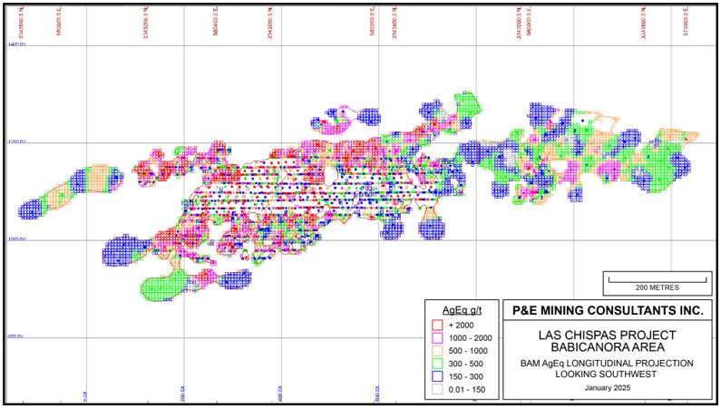
Source: P&E, 2025
| |
| Figure 11‑6: | AgEq Longitudinal Projection for BAN_SE |

Source: P&E, 2025
| |
| Figure 11‑7: | AgEq Longitudinal Projection for BAS_Main |
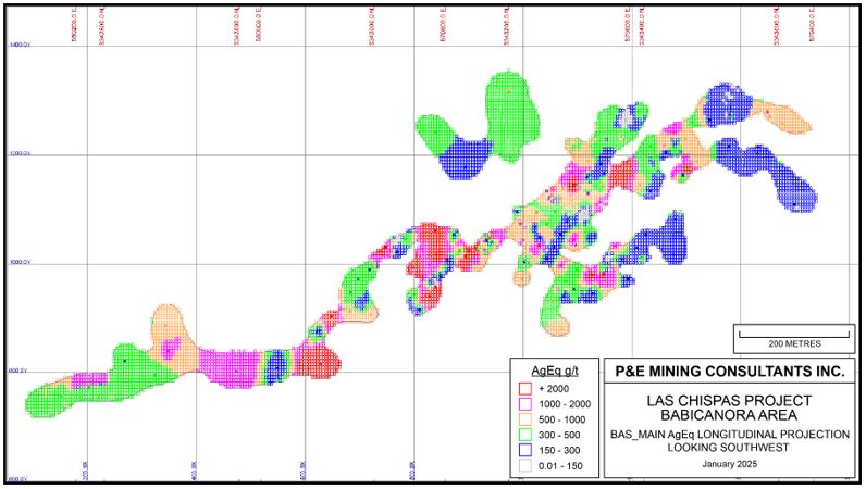
Source: P&E, 2025
| |
| Figure 11‑8: | AgEq Longitudinal Projection for BAV |

Source: P&E, 2025
| |
| Figure 11‑9: | AgEq Longitudinal Projection for LC |
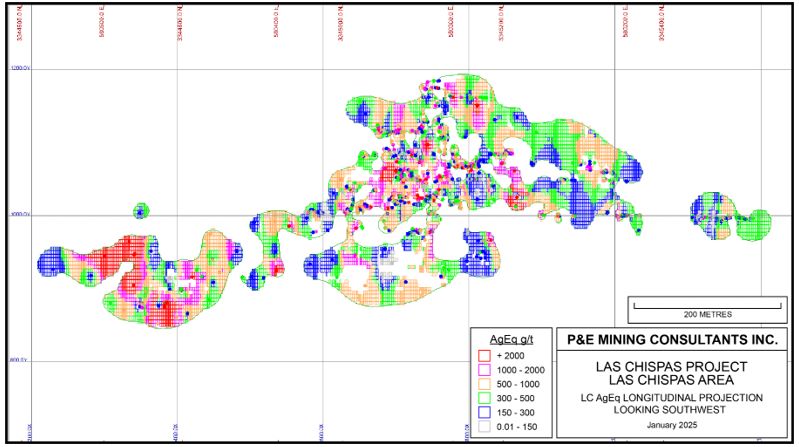
Source: P&E, 2025
| |
| 11.12 | Mineral Resource Classification |
In the QP’s opinion, the Mineral Resource Estimate is supported by the drilling, assaying and exploration work completed up to the Effective Dates and is based on spatial continuity of the mineralization within a potentially mineable shape. These factors are sufficient to indicate that the estimate is a reasonable potential for economic extraction, thus qualifying it as a Mineral Resource under S-K 1300. The Mineral Resource was classified as Measured, Indicated and Inferred, based on the geological interpretation, variogram performance, and drill hole spacing.
A Measured Mineral Resource was classified around the Babicanora Area underground only with a 10 m range extended up- and down-dip from areas where underground grade-control sampling and mapping had been completed and interpolated with both underground channel and chip samples and drill holes within this area.
Indicated Mineral Resources were classified for the blocks interpolated with the Pass 1 in Table 11‑9 used at least two drill holes within a minimum of 35 m and overall, 50 m mean distance.
Inferred Mineral Resources were classified for all remaining grade blocks within the mineralized veins.
The classifications were adjusted on a longitudinal projection to reasonably reflect the distribution of each classification.
| 11.13 | AgEq Cut-off Value Calculation |
The Mineral Resource Estimate was derived from applying AgEq cut-off values to the block models and reporting the resulting tonnes and grades for potentially mineable areas. The following parameters were used to calculate the AgEq cut-off values that determine the underground mining potentially economic portions of the constrained mineralization.
| • | Ag price: US$27/oz (approximate 18-month trailing average as of December 31, 2024); |
| • | Ag process recovery: 98%; |
| • | Marginal mining cost: $55/t; |
| • | Processing cost: $45/t; and |
| • | G&A: $27/t. |
The AgEq cut-off value of the underground Mineral Resource is calculated as follows:
| • | ($55+ $45+$27)/($27/31.1035 x 98%) = ~150 g/t AgEq |
| 11.14 | Las Chispas Operation Mineral Resource Estimate |
The Las Chispas Operation Mineral Resource Estimate includes in-situ vein mineralization. The Mineral Resource Estimate with an effective date of December 31, 2024, is tabulated in Table 11‑10.
| |
| Table 11‑10: | Mineral Resource Estimate (1-10) |
Mineral Resources Exclusive of Mineral Reserves | Classification | Tonnes (k) | Au (g/t) | Ag (g/t) | Contained Au (k oz) | Contained Ag (k oz) | Silver Equivalent Average Cut- off Grade (g/t AgEq) | Metallurgical Recovery | |
| Ag (%) | Au (%) | ||||||||
Babicanora Area Veins | Measured | 106 | 10.45 | 1,067.9 | 35 | 3,623 | 150 | 98 | 98 |
| Indicated | 811 | 3.88 | 312.9 | 101 | 8,153 | 150 | 98 | 98 | |
| Meas + Ind | 916 | 4.63 | 399.8 | 136 | 11,776 | 150 | 98 | 98 | |
Las Chispas Area Veins | Indicated | 182 | 3.28 | 451.7 | 19 | 2,646 | 150 | 98 | 98 |
| Total | Meas + Ind | 1,098 | 4.41 | 408.4 | 156 | 14,422 | 150 | 98 | 98 |
Babicanora Area Veins | Inferred | 747 | 3.76 | 242.8 | 90 | 5,829 | 150 | 98 | 98 |
Las Chispas Area Veins | Inferred | 411 | 4.03 | 322.2 | 53 | 4,260 | 150 | 98 | 98 |
| Total | Inferred | 1,158 | 3.86 | 271.0 | 143 | 10,088 | 150 | 98 | 98 |
Notes: 1 The estimate of Mineral Resources may be materially affected by environmental, permitting, legal, title, taxation, socio-political, marketing, or other relevant issues. 2 The Inferred Mineral Resource in this estimate has a lower level of confidence than that applied to an Indicated Mineral Resource and must not be converted to a Mineral Reserve. It can be reasonably expected that the majority of the Inferred Mineral Resource could be upgraded to an Indicated Mineral Resource with continued exploration. 3 The Mineral Resource is estimated using Subpart 229.1300 – Disclosure by Registrants Engaged in Mining Operations. 4 Mined areas as of December 31, 2024, were depleted from the wireframes and block models. 5 AgEq is based on Ag:Au ratio of 79.51:1 calculated using approximately $2,100/oz Au and $27/oz Ag, with average metallurgical recoveries of 98% for Au and Ag with 99.9% payable for both Au and Ag. The Au and Ag prices were the approximate December 31, 2024 18-month trailing average, which was chosen to be representative of the near-term future price evironment. 6 Mineral Resources are exclusive of Mineral Reserves. 7 All numbers are rounded. 8 The cut-off grade (COG) used for in-situ Mineral Resources is 150 g/t AgEq calculated from $55/tonne mining cost, $45/tonne process cost, and $27/tonne G&A cost. 9 The point of reference for the Mineral Resource estimate is its in-situ location in the mine. 10 Mineral Resources are 100% wholly-owned and attributable to the Company.
| 11.15 | Model Validation |
The QPs validated the block models generated by Las Chispas Operations using many industry standard methods, including block model interpolation using GEOVIA GEMSTM, visual and statistical methods.
Visual examination of composites and adjacent block grades on successive plans and cross-sections were performed on-screen to confirm that the block models correctly reflect the distribution of composite grades. The review of estimation parameters included:
| • | Number of composites used for estimation; |
| • | Number of drill holes used for estimation; |
| • | Mean distance to sample used; |
| • | Number of passes used to estimate grade; |
| • | Actual distance to closest point; |
| • | Grade of true closest point; and |
| • | Mean value of the composites used. |
| |
A comparison of mean grades of blocks of five of the largest vein (BAM Main including BAM_CEN ,
BAN SE, BAS Main, BAV Main and LC Main, when combined account for 61% of the total estimated AgEq oz of the In-situ vein Mineral Resources) block models interpolated with ID3 by Las Chispas Operations and the QPs at 150 g/t AgEq cut-off grade are presented in Table 11‑11.
| Table 11‑11: | Average Grade Comparison of the Block Models of the Main Veins by Software Type |
| Vein | Data Type | Au (g/t) | Ag (g/t) |
| BAM Main | Block model ID3_Leapfrog | 8.12 | 728 |
Block model ID3_Gems | 8.11 | 728 | |
| BAN Main SE | Block model ID3_Leapfrog | 15.7 | 2,119 |
Block model ID3_Gems | 15.7 | 2,109 | |
| BAS Main | Block model ID3_Leapfrog | 6.3 | 319 |
Block model ID3_Gems | 5.8 | 331 | |
| BAV Main | Block model ID3_Leapfrog | 20.7 | 1,983 |
Block model ID3_Gems | 20.6 | 1,918 | |
Block model ID3_Leapfrog | 4.9 | 685 | |
Block model ID3_Gems * | 4.1 | 553 |
Notes:
ID3 = Au and Ag interpolated with Inverse Distance Cubed.
Leapfrog™ = Block model was constructed using the Leapfrog™ software by Las Chispas Operations.
Gems™ = Block model was verified using GEOVIA GEMS™ software by the QPs.
* = used all UG channel/chip samples, while Las Chispas Operations ignored some UG channel/chip samples which located within a range of 10m to the nearest drill hole.
Local trends for gold and silver were evaluated by comparing the Las Chispas Operations and QP estimate against the composites. The selected special swath plots of the five largest veins, including mined areas, are shown in Figure 11‑10 through Figure 11‑4.Source: P&E(This Study). Notes: _COM: Uncapped composite; _CAP: Capped composite; _SIL: estimated by Las Chispas Operations; _QP: estimated by the QPs.
| |
| Figure 11‑10: | Babicanora Main Vein (including BAM_Main, RDCLF and Central) Au and Ag Grade Swath Plot |
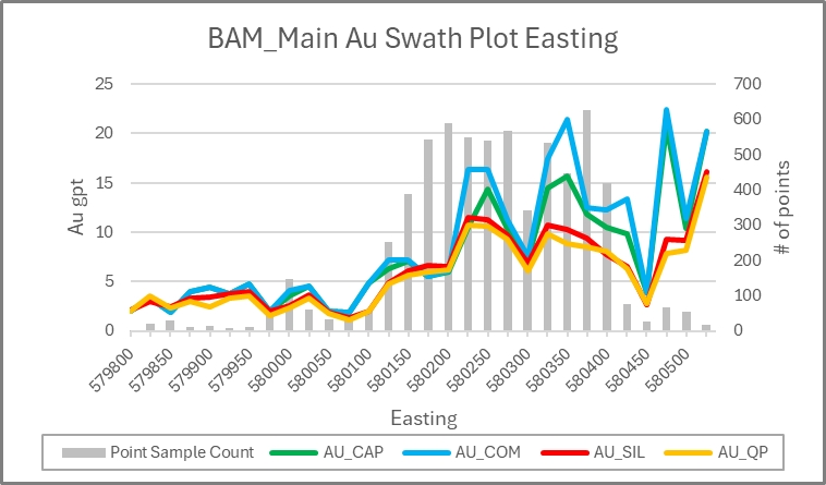
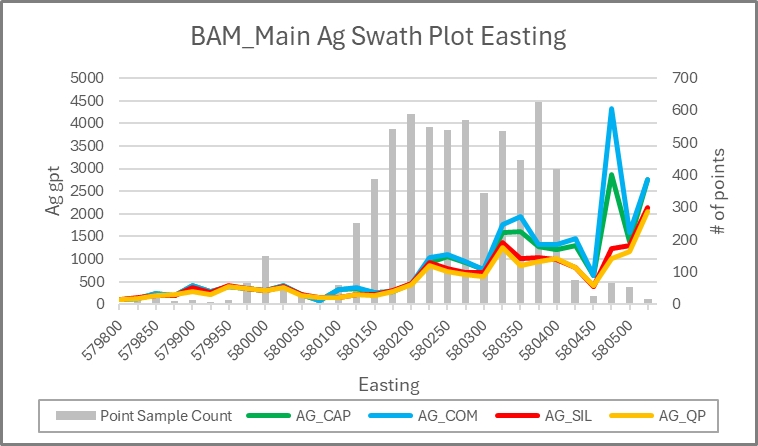
Source: P&E, 2025.Notes: _COM: Uncapped composite; _CAP: Capped composite; _SIL: estimated by Las Chispas Operations; _QP: estimated by the QPs.
| |
| Figure 11‑11: | Babicanora Norte SE Vein Au and Ag Grade Swath Plot |
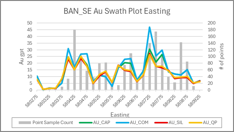

Source: P&E, 2025. Notes:2024 _COM: Uncapped composite; _CAP: Capped composite; _SIL: estimated by Las Chispas Operations; _QP: estimated by the QPs.
| |
| Figure 11‑12: | Babicanora Sur Main Vein Au and Ag Grade Swath Plot |


Source: P&E 2025. Notes: _COM: Uncapped composite; _CAP: Capped composite; _SIL: estimated by Las Chispas Operations; _QP: estimated by the QPs.
| |
| Figure 11‑13: | Babicanora Vista Main Vein Au and Ag Grade Swath Plot |
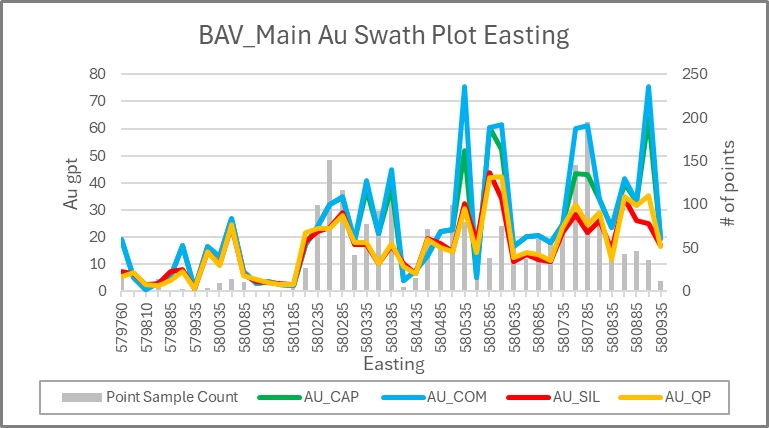

Source: P&E, 2025. Notes: _COM: Uncapped composite; _CAP: Capped composite; _SIL: estimated by Las Chispas Operations; _QP: estimated by the QPs.
| |
| Figure 11‑14: | Las Chispas Main Vein Au and Ag Grade Swath Plot |


Source: P&E, 2025. Notes: _COM: Uncapped composite; _CAP: Capped composite; _SIL: estimated by Las Chispas Operations; _QP: estimated by the QPs.
| |
| 11.16 | Potential Risks in Developing the Mineral Resource |
The QPs are of the opinion that there are no known legal, political, environmental, or other risks that could materially affect the potential development of the Mineral Resources.
Due to the fact that Las Chispas is a producing mine, there are moderate to low risks to continuing development of the Mineral Resource at the site, which are listed as follows in Table 11‑12.
| Table 11‑12: | Risks by Category |
| Risk Category | Explanation | Risk |
| Geology | Uncertainty in geological interpretation may affect mineral estimates in areas that have not been mined. | Moderate |
Grade Estimation | Bulk Density: Bulk density is assigned on a vein basis, based on the average measured bulk density. Local variations in bulk density may affect tonnage. | Low |
| Compositing: Composite data may occur in small vein intervals. This can lead to a local estimation bias. | Low | |
Outlier Management: Grade capping is used to limit the influence of anomalous high-grade samples on a vein basis. Local grade trends may therefore be biased. | Low | |
Minimum width: The Las Chispas Mineral Resource does not dilute narrow vein widths. No minimum vein width was applied. The selected narrow vein thickness may be somewhat over-optimistic and high grade biased. | Moderate | |
Classification: Classification is assigned algorithmically based on the number of samples within the search ellipse. This may create a small number of locally incongruent block classifications. | Low | |
| Classification: A 10 m range for Measured Mineral Resources and a minimum of 2 samples for Indicated Mineral Resources may create a small number of blocks that are inappropriately classified. | Low | |
Estimation Strategy: Inverse Distance Cubed estimation is used where a reasonable variogram can be modeled. This may result in some local small tonnage high biased grades. | Low | |
| Sampling Methods | In areas of active mining chip/channel samples predominate, which can adversely affect local grade estimates depending on the quality of underground sampling. | Low |
| Data | Data Management: All information is stored in a corporate database. Mineral resources are calculated for each vein in Leapfrog. Small database errors may contribute to grade estimation errors. | Low |
| Reconciliation | Detailed block model reconciliation is carried out on a monthly basis using CMS surveys, stockpile topographic surveys and truck counts. Truck counts are a potential source of tonnage error. | Low |
| 11.17 | Mineral Resource Estimate Conclusion |
The Qualified Persons for this Individual Technical Report Summary section consider the Mineral Resource Estimate block model and Mineral Resource classification reported by Las Chispas Operations to represent a reasonable estimation of the total Mineral Resources for the Las Chispas Property regarding compliance with: generally accepted industry standards and guidelines; the methodology used for grade estimation; the classification criteria used; and the actual implementation of the methodology in terms of Mineral Resource estimation and reporting.
The Mineral Resources reported by Las Chispas Operations have been estimated to conform with the requirements of the CRIRSCO Definitions, in addition to the guidelines prepared by the Securities and Exchange Commission under the S-K §229.1300 to S-K §229.1305 regulations. Mineral Resources are not Mineral Reserves and do not have demonstrated economic viability.
| |
| 12.1 | Introduction |
Mineral reserves are estimated at Babicanora (Main, Norte, Sur, Vista, El Muerto, and Granaditas), and Las Chispas (Las Chispas, Giovani, Giovani Mini, Luigi, Luigi FW and William Tell) mines (Figure 12-1 to Figure 12-6). All estimates envisage underground mining methods. Mineral reserves were converted from measured and indicated mineral resources. Inferred mineral resources were set to waste. The mine plans assume underground mining using longhole open stoping, cut and fill stoping and resue stoping, using trackless equipment, and a combination of cemented rock fill (CRF) and unconsolidated rockfill (URF) for backfill (URF). Target mining rates are 1,250 t/d initially, increasing to 1,500 t/d at its peak for the LOM.
| 12.2 | Development of Mining Cases |
The Mineral Reserve Estimate is based on the following inputs and considerations:
| • | Mineral resource block model, with estimated tonnage, gold, and silver grades; |
| • | Cut-off grade calculations; |
| • | Stope and development designs; |
| • | Geotechnical and hydrogeological information; |
| • | Estimates for mining recovery and dilution; |
| • | Depletion from previous mining; |
| • | Consideration of other modifying factors. |
Deswik mine planning software was used for the mine design, 3D modeling, and interrogation of the 3D mining model against the block model.
The surveyed “as-built” mining excavations were depleted from the designed solids and the resource block model.
Mining, geotechnical, and hydrological factors were considered in the estimation of the mineral reserves, including the application of dilution and ore recovery factors.
| 12.3 | Designs |
Mining excavations (stopes and ore development) were designed to include mineralized material above the cut-off grade. These excavations were then assessed for economic viability. In addition to the mining cut-off grade, an incremental cut-off grade (excluding the mining cost) was calculated to classify mineralized material mined as a result of essential development to access higher grade mining areas. Mineralized material above this cut-off grade will add value, and is therefore, included as process plant feed. Waste and mineralized material below the incremental cut-off will be disposed of on surface in waste rock storage facilities (WRSFs) or will be used underground as backfill.
| |
Figure12‑1: | Deposit Layout Plan |

Source: Coeur, 2025
| |
Figure 12‑2: | Babicanora Complex Plan View |
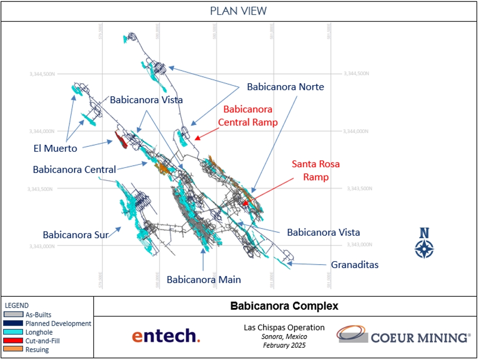
Source: Coeur, 2025
| |
| Figure 12‑3: | Babicanora Vein Overview Plan View |
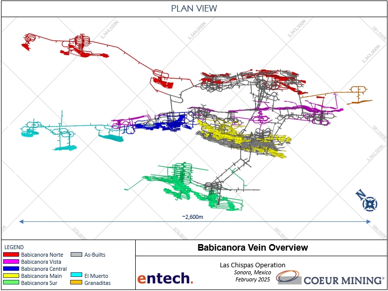
Source: Coeur, 2025
| |
Figure 12‑4: | Babicanora Looking Northeast |

Source: Coeur, 2025
| |
Figure 12‑5: | Las Chispas Complex Plan View |

Source: Coeur, 2025
| |
Figure 12‑6: | Las Chispas Looking Northeast |
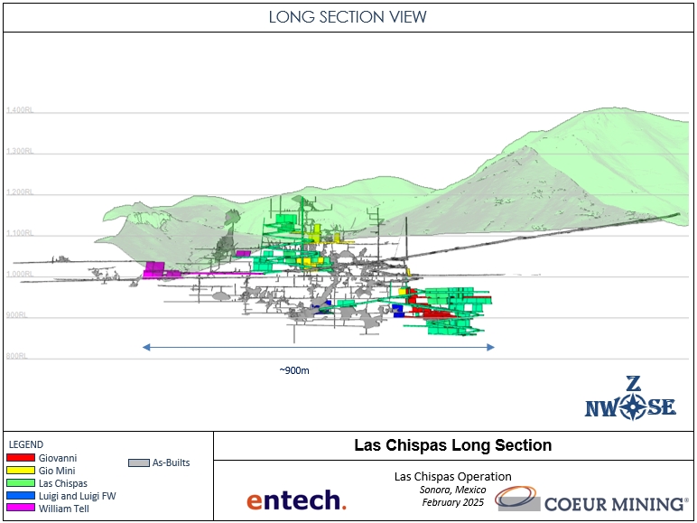
Source: Coeur, 2025
All designed excavations in the Mineral Reserve have been tested for a positive economic return. However, other costs not included in the economic review will be incurred, such as costs related to underground infrastructure installations, capital equipment purchases, and sustaining capital. In addition to these costs, there are taxes and royalties that are payable based on net income.
The resulting mine plan was analyzed in a financial model and is economically viable.
| |
| 12.4 | Input Assumptions |
Stope designs were generated for the planned mining methods using the cut-off grade to target material for inclusion. Stope designs were completed using the Deswik Mineable Shape Optimizer software. Centerlines representing ore development drives were digitized to represent ore development and were used to create a 3D solid model in Deswik Spatial. The stope solids were cut using the ore development solids, using Boolean routines in the planning software. The resulting 3D model formed the basis of the Mineral Reserve Estimate.
Silver equivalent (AgEq) cut-off grades were calculated for the deposits, with mineral reserves estimated and reported above this cut-off. The AgEq cut-off was calculated as follows:
A silver:gold value ratio was used to convert gold grades to silver equivalent grades and is calculated using the following formula:

Silver equivalent grades were calculated using the following formula:

Where, AgEq, Ag and Au are the silver equivalent grade, silver grade, and gold grade, respectively, in g / t.
The input parameters to the cut-off grades and the resulting grade cut-off for Mineral Reserves reporting are provided in Table 12-1.
| 12.5 | Ore Loss and Dilution |
The following sources of dilution were identified:
| • | Overbreak into the hanging wall or footwall rocks following drilling and blasting operations; |
| • | Rock failures (slough) from rock walls adjacent to the stope boundaries as a result of weak rock mass characteristics; and, |
| • | Backfill dilution from over mucking into the stope floor. |
Ore dilution factors to account for overbreak and wall slough (waste rock dilution) from the hanging wall and footwall surfaces were estimated based on the consideration of geotechnical information and stope reconciliations and were applied to stope shapes in the stope optimization software.
Unplanned dilution was added during the MSO stage and then optimized for grade. Equivalent Linear Overbreak Slough (ELOS) for longhole varies based on geotechnical conditions in each of the stoping areas, with overall ELOS varying from 1.0 m to 1.5 m, including of 0.5 – 1.0 m hangingwall and 0.25 m – 0.5 m footwall dilution . ELOS for resue considers 0.2 m hangingwall and 0.2 m footwall dilution. Cut and fill mining was assumed as breasting in all cases, using the ore sill drive width of 3.5 m as a minimum mining width inclusive of dilution. The resulting stope shapes were reviewed for practicality of mining, with impractical mining shapes removed or adjusted. Cemented Rock Fill (CRF) and Unconsolidated Rock Fill (URF) are used to backfill mined-out stopes in order to enhance ore recovery, provide mine stability, and eliminate the need for permanent ore pillars to be left.
| |
Ore losses can occur during mining as a result of:
| • | Stope under-break and unrecoverable bridging; |
| • | Unrecovered ore stocks due to flat dipping footwalls and stope draw point geometry; |
| • | Misclassification of material resulting in ore hauled inadvertently to waste dumps; and, |
| • | Abandoned ore stocks due to excessive dilution from stope wall failures. |
A development design was produced to align with the resulting stope shapes that tied into the existing underground as-builts. The development design follows current site design criteria and geotechnical recommendations. A development dilution factor of 5% and recovery factor of 98% was applied.
Stope shapes were depleted with development drives. Estimated maximum mining recoveries for stoping was 95%, with lower recoveries assumed for specific locations due to ground conditions, quality of existing backfill above and pillar requirements.
Table 12-2 summarizes the dilution factors for the various mining methods used at Las Chispas.
| Table 12‑1: | Input Parameters to Cut-off Grade Determination, Mineral Reserves |
| Parameter | Units | Value/Value Range (from/to) |
| Silver price | $ / oz | 23.50 |
| Gold price | $ / oz | 1,800.00 |
| Silver recovery | % | 97.50 |
| Gold recovery | % | 98.00 |
| Silver payable | % | 99.90 |
| Gold payable | % | 99.85 |
| Ag:Au value ratio | Ag:Au | 76.95 |
| Production Mining cost | $ / t | 58.06–239.511 |
| Development Mining cost | $ / t | 27.40 |
| Processing | $ / t | 45.72 |
| Underground G&A | $ / t | 12.81 |
| Site G&A | $ / t | 20.70 |
| Sustaining Capital | $x / t | 7.64 |
| AgEq cut-off grade | g / t | 235 – 4832 |
| Marginal development AgEq cut-off grade | g / t | 62.00 |
Note 1: Average Production Mining Cost = 68.72 $USD / t
Note 2: Average AgEq cut-off grade = 250 g / t
| |
| Table 12‑2: | Dilution Factors |
| Mining Method | Unplanned Dilution | |
| Development (Rock) | 5% | |
| Longhole Stoping (Rock) | 1.0 m – 1.5 m ELOS1 (0.5 – 1.0 m HW, 0.25 m - 0.5 m FW) | |
| Cut and Fill Stoping (Rock) | 0.2 m ELOS (0.1 m HW, 0.1 m FW) | |
| Resue Stoping (Rock) | 0.4 m ELOS (0.2 m HW, 0.2 m FW) | |
| All (Backfill) | 3% |
Note 1: Varies based on geotechnical conditions in each area
| 12.6 | Commodity Prices |
The silver price assumed for the Mineral Reserve estimate is US $23.50/oz and the gold price assumed is US$1,800/oz and details of this are outlined in Section 16. The QP reviewed the metal prices used in the calculation of the Mineral Reserve estimate and believes that they are reasonable to use over the 7-year mine life given the consideration of long-term consensus pricing by analysts (5-year forecast), 3-year historical averages and industry peer comparisons.
| 12.7 | Mineral Reserve Statement |
Mineral reserves are reported using the mineral reserve definitions set out in S-K 1300. The reference point for the Mineral Reserve Estimate is the point of delivery to the process plant. Mineral reserves are reported in Table 12‑1. Mineral reserves are current at December 31, 2024. Estimates are reported on a 100% basis.
The Qualified Person for the estimate is Mr. Joseph Wallick, P.Eng.
| |
| Table 12‑3: | Mineral Reserve Estimate |
| Zone/Deposit | Mineral Reserve Classification | Tonnes (kt) | Grade | Contained Ounces | Silver Equivalent Average Cut-off Grade (g/t AgEq) | Metallurgical Recovery | |||
| Ag (g/t) | Au (g/t) | Ag (koz) | Au (koz) | Ag (%) | Au (%) | ||||
Babicanora | Proven | 606 | 537.9 | 5.04 | 10,482 | 98 | 250 | 97.5 | 98.0 |
Probable | 2,164 | 264.8 | 3.16 | 18,426 | 220 | 250 | 97.5 | 98.0 | |
| Subtotal proven and probable | 2,770 | 324.6 | 3.57 | 28,908 | 318 | 250 | 97.5 | 98.0 | |
Las Chispas | Proven | - | - | - | - | - | 250 | 97.5 | 98.0 |
Probable | 285 | 273.2 | 2.10 | 2,505 | 19 | 250 | 97.5 | 98.0 | |
| Subtotal proven and probable | 285 | 273.2 | 2.10 | 2,505 | 19 | 250 | 97.5 | 98.0 | |
Stockpiles | Proven | 107 | 609.1 | 5.67 | 2,104 | 20 | 250 | 97.5 | 98.0 |
Probable | - | - | - | - | - | - | 97.5 | 98.0 | |
| Subtotal proven and probable | 107 | 609.1 | 5.67 | 2,104 | 20 | - | 97.5 | 98.0 | |
| Total Proven and Probable Mineral Reserves | Total proven | 714 | 548.6 | 5.13 | 12,586 | 118 | 250 | 97.5 | 98.0 |
| Total probable | 2,449 | 265.8 | 3.03 | 20,931 | 239 | 250 | 97.5 | 98.0 | |
| Total proven and probable | 3,163 | 329.6 | 3.51 | 33,516 | 357 | 250 | 97.5 | 98.0 | |
Notes to Accompany Mineral Reserves Table:
1 The Mineral Reserve estimates are current as of December 31, 2024 and are reported using the definitions in Item 1300 of Regulation S–K (17 CFR Part 229) (S-K 1300). 2 The reference point for the Mineral Reserve Estimate is the point of delivery to the process plant. The estimate is current as at December 31, 2024. The Qualified Person for the estimate is Mr. Joseph Wallick, an employee of Coeur Mining. 3 The estimate uses the following key input parameters: assumption of conventional underground mining; silver price of US$23.50 / oz and gold price of US$1,800 / oz; reported above an average silver equivalent cut-off grade of 250 g / t silver equivalent and an incremental development cut-off grade of 62 g / t AgEq; metallurgical recovery assumption of 97.5% for silver and 98.0% for gold; mining dilution assumes 5% for development, 1 meter to 1.5 meters of ELOS (0.5 m – 1.0 m of hangingwall and 0.25 m – 0.5 m of footwall dilution) depending on geotechnical conditions in each longhole stoping location, 0.2 meter ELOS (0.1 m of hangingwall and 0.1 m of footwall dilution) for cut and fill, 0.4 meter ELOS (0.2 m of hangingwall and 0.2 m of footwall dilution), and 3% waste dilution for backfill; mining loss of 2% for development and 5% for stoping was applied, additional losses have been included to account for the required pillars in uphole stopes that cannot be filled; variable production mining costs that range from US$58.06–US$239.51/t, development mining costs of US$27.40/t, process costs of US$45.72/t, site general and administrative costs of US$20.70/t, underground general and administrative costs of US$12.81/t, and sustaining capital costs of US$7.64/t. 4 Rounding of tonnes, grades, and troy ounces, as required by reporting guidelines, may result in apparent differences between tonnes, grades, and contained metal contents.
| 12.8 | Uncertainties (Factors) That May Affect the Mineral Reserve Estimate |
Factors that may affect the Mineral Reserve estimates include:
| • | Commodity prices: the mineral reserve estimates are sensitive to metal prices. Coeur’s current strategy is to sell most of the metal production at spot prices, exposing the company to both positive and negative changes in the market, both of which are outside of the company’s control; |
| |
| • | Metallurgical recovery: long term changes in metallurgical recovery could also have an impact on the mineral reserve estimates. For example, a 10% change in metallurgical recovery has the same impact as a 10% change in metal prices. However, the metallurgy is well understood, and as a result, the mineral reserve estimates are considered to be less sensitive to long-term factors affecting metallurgical recovery, compared to the sensitivity to metal prices, which tend to have greater variances; |
| • | Mining method will change from cut and fill and resue to longitudinal longhole stoping based on actual vein widths mined which could result in higher dilution quantities, lower costs and higher productivity which can impact grade. All of these factors could impact cut-off grades, reserve estimates and economics; |
| • | Operating costs: higher or lower operating costs than those assumed could also affect the mineral reserve estimates. While the trend over the last few years showed operating cost reductions at the Las Chispas Operations, this trend could reverse and costs could increase over the life of the Project, due to factors outside of the company’s control. However, of the factors discussed in this section, the QP considers the mineral reserve sensitivity to changes in operating costs to be low; |
| • | Dilution: additional dilution has the effect of increasing the overall volume of material mined, hauled and processed. This results in an increase in operating costs and could result in mineral reserve losses if broken stopes are diluted to the point where it is uneconomic to muck, haul, and process the material and the broken stocks are abandoned. The operations have developed a number of methods to control dilution, including the installation of stope support, a flexible mine plan with the ability to limit stope wall spans, and good development practices that avoid undercutting the stope hanging wall. To assist in these efforts, site geotechnical reviews are regularly completed by external consultants, and a geotechnical engineer is employed by the mine. In the opinion of the QP, sufficient controls are in place at the Las Chispas Operations to manage dilution, and the risk of material changes to the mineral reserve from dilution above the amounts used in the Mineral Reserve Estimate is low; |
| • | Geotechnical: geotechnical issues could lead to additional dilution, difficulty accessing portions of the ore body, or sterilization of broken or in situ ore. In addition to the controls discussed in the dilution section there are significant management controls in place to effectively mitigate geotechnical risks. Designed openings are evaluated for stability using the Modified Stability Graph method. There is regular underground geotechnical mapping, and comprehensive geotechnical reviews are held on a weekly basis. The QP considers that sufficient controls are in place at the Las Chispas Operations to effectively manage geotechnical risk, and the risk of significant impact on the Mineral Reserve Estimate is low; |
| • | Hydrogeological: unexpected hydrogeological conditions could cause issues with access and extraction of areas of the Mineral Reserve due to higher than anticipated rates of water ingress. The QP considers the risk of encountering hydrogeological conditions that would significantly affect the Mineral Reserve Estimate is low; |
| • | Geological and structural interpretations: changes in the underlying geology model including changes in local interpretations of mineralization geometry and continuity of mineralized zones, changes to geological and mineralization shape and geological and grade continuity assumptions, and density and domain assignments could result in changes to the geology model upon which Mineral Reserve Estimate is based; |
| • | Permitting and social license: inability to maintain, renew, or obtain environmental and other regulatory permits, to retain mineral and surface right titles, to maintain site access, and to maintain social license to operate could result in the inability to extract some or all of the mineral reserves. |
| |
| 13 | MINING METHODS |
| 13.1 | Introduction |
The Babicanora, Las Chispas mines use conventional underground mining and conventional equipment. The overall production rate is 1,250 t/d initially and peaks at 1,500 t/d for the LOM. Figure 13‑1 show the final mine design by vein and mining method.
Figure 13‑1: | Las Chispas Final Mine Design Plan View by Vein |

Source: Coeur, 2025
| 13.2 | Geotechnical Considerations |
The Las Chispas Operations Technical Services Department maintains a Ground Control Management Plan that is updated annually and serves to provide mine personnel with operating, monitoring, and quality control/assurance guidance. The Ground Control Management Plan specifies ground support standards and identifies where they are applicable in the mines.
| |
| 13.2.1 | Babicanora |
Knight Piésold (KP) performed a geotechnical assessment of the mine area, with site visits being conducted in 2022 and 2023, and provided guidance on developing RMR logging procedures and calculated rock mass rating (RMR76). Due to the varying nature of the multiple veins, the RMR76 values also vary significantly across the deposit, with some areas having values in the range of 20–35, or a “Poor” rock quality, up to a RMR76 rating of “Good” or 70. The areas where ground conditions were demonstrated as “Poor” have been considered for cut and fill mining and resue mining.
Initial stope dimensions were developed using the Modified Stability Graph method, which predicts equivalent linear overbreak slough values (Pakalnis, 2016). Modifications based on variability and updated geotechnical models were made as the mine developed. Updated designs are modelled using two and three-dimensional numerical simulation software to provide final design for each access and stope.
Based on the calculated modified stability number (N’) values, the planned stope surfaces at Babicanora are estimated to have equivalent linear overbreak slough values of 1.0 m – 1.5 m, accounting for 0.5 m – 1.0 m of hangingwall overbreak and 0.25 – 0.5 m of footwall overbreak, depending on vein dimensions, structural interpretation, and rock quality locally. Stope spans range from 10 – 25 m along strike, depending on vein dimensions, structural interpretation, and rock quality locally.
The Las Chispas Operation maintains current ground support standards based on the ground conditions encountered, typically containing resin rebar in the backs and shoulders, along with welded wire mesh. In some poorer ground conditions, in-cycle shotcrete with a thickness of 5 cm is added, and intersections require either Swellex or cable bolts, depending on the span. In addition to this, cable bolts are typically installed in the hangingwall of the sill drives of stopes.
The most recent geotechnical review was conducted in 2023 to review updated support methods, maximum allowable stable stope spans, mining sequence, and overall mine stability.
The geotechnical conditions at Las Chispas are classified with rock qualities ranging from 60 to 65, which falls in the “Good” category. Ground support schemes and stope parameters are similar to those at Babicanora, however there is no planned cut and fill or resue mining considered for Las Chispas due to the better overall ground conditions.
Based on the calculated modified stability number (N’) values, the majority of the planned stope surfaces at Babicnaora are estimated to have equivalent linear overbreak slough values of 1.0 m, accounting for 0.5 m of hangingwall overbreak and 0.5 m of footwall overbreak. Stope spans range from 10– 25 m along strike, depending on vein dimensions, structural interpretation, and rock quality locally.
The most recent geotechnical review was conducted in 2023 to review updated support methods, maximum allowable stable stope spans, mining sequence, and overall mine stability.
| |
| 13.3 | Hydrogeological Considerations |
| 13.3.1 | Babicanora |
Permeability of the volcanic rock units in all mines is low to very low. Persistent inflows generally occur within larger fault structures. Flows increase and decrease seasonally if the structure is connected to the surface. Access ramps encountered significant water inflows from these structural features during early development; however, over time, inflows into the mine have diminished as local storage is removed. Increases in flow currently are directly related to opening new developments laterally or ramping downward to lower levels. A series of 10 to 30 kW pumps, in a series of dirty water sumps, main collection sumps and solid separation sumps will dewater Babicanora.
Hydro-Resources Inc (HRI) completed a review of the hydrogeological and structural models for the operation. Expected mine inflows are in the range of 20 L / s at Babicanora, plus any additional water used in the mining process.
| 13.3.2 | Las Chispas |
Las Chispas will be dewatered similarly to Babicanora, with a series of 10 to 30 kW pumps, in a series of dirty water sumps, main collection sumps and solid separation sumps.
Based on the pump test results completed by HRI, in Las Chispas the maximum inflow is expected to be 9.4 L / s, and this is what LOM dewatering designs for Las Chispas have been based on.
| 13.4 | Operations |
| 13.4.1 | Babicanora |
Primary access and egress to the Babicanora mine is from surface via two ramps. The Santa Rosa and Babicanora Central portals can handle the proposed trucking fleet and will also be used as intake flows for the primary ventilation circuit.
Babicanora contains mineralized zones along a strike length of 2,600 m and a depth of 450 m. The mineralized zones are varying in dip and thickness both along strike and at depth. The Babicanora mine includes the following veins of mineralization, the Babicanora Norte (BAN) extends furthest to the north and the El Muerto (EM) vein extends the deepest, with the Granaditas (GRA) vein extending furthest south. Additional veins include Babicanora Vista (BAV), Babicanora Main (BAM), Babicanora Sur (BAS) and Babicanora Central (BAC). While all geometries are suitably extracted using the longitudinal longhole stoping method, particular areas in the EM vein have been selected for cut and fill mining due to geotechnical considerations. Additionally, resue mining sees limited use in the BAC and BAM veins, to minimize dilution in high-grade narrow veins.
Ramp access is driven at 15% grades, mine access drifts and other capital development is primarily developed at 4.5 m wide by 4.5 m high, and ore drives are developed at 3.3 m wide by 4.0 m high.
Key input parameters to the mine design include mechanized diesel and electric drill, load, and haulage systems. Production rates for Babicanora are 400 thousand tonnes per year (kt/a) for ore and 300 kt/a for waste over the LOM. The material handling system uses a load-haul-dump (LHD) and truck transport system of ore loading and hauling to an interim surface stockpile. Ore is separated at surface into stockpiles to support blending prior to transport to the plant run-of-mine (ROM) stockpile. Waste from development is either directly transported from development to backfilling pockets in active stopes, mixed with cement for cemented rockfill to be utilized in the backfilling of stopes, or stockpiled underground for later use as backfill.
| |
Mining methods used at Babicanora include longitudinal sublevel stoping, cut and fill, and resuing. Longitudinal sublevel stoping is the primary mining method, and in areas where there is either poorer ground conditions, or veins are very narrow, either cut and fill or resuing is used.
Access to longitudinal stoping areas is via level accesses perpendicular to the vein strike, from a ramp that is developed primarily in the footwall of the vein to be mined. Stope development is completed along strike of the vein, and the longitudinal stoping is completed by retreating from the extents of the vein back to the central access. The stopes (10-25 m of strike) are excavated and backfilled with either cemented rockfill or unconsolidated rockfill, depending on the area. The open stope is backfilled, and the extraction continues in sequence. Level or stope heights in Babicanora are generally 18 m, with the exception of BAS, which has a general stope height of 15 m.
Cut and fill is utilized in the BAC vein of Babicanora. Cut and fill breasting will be applied in this area, and the mining will initially be accessed by developing a pivot drive. From the pivot drive, an ore sill will be developed to the economic extents of the orebody. Once the sill is complete, rockfill will be placed to create a new working floor for the next cut to be mined in an overhand fashion. A new access to the next lift will be taken, through slashing of the pivot drive back.
Four areas of Babicanora will utilize the resuing mining method: BAC, BAN, BAV and EM. These selected high grade areas have a minimum width of 0.9m inclusive of ELOS. A sill drive is developed, similar to longitudinal stoping or cut and fill, and then the narrow ore vein is mined with up-hole drilling. After the ore is mined, the waste is then mined and utilized as the floor of the next lift, with either excess waste removed, or additional waste added to obtain a new working floor.
Lateral development is completed using conventional mechanized drilling and blasting methods. Drift rounds are drilled using twin boom, electric/hydraulic drill jumbos. Ground support is installed using mechanical/electrical bolting machines and (when required) shotcrete is applied with a shotcrete machine. Mine services (air, water, compressed air, electrical and communication cables) are extended to the working areas.
Longhole production drilling of stopes is completed using electric/hydraulic vertical hammer drill rigs. Production drilling is mainly done in pattern format in a down dip configuration, with the holes drilled parallel to the dip of the orebody.
| 13.4.2 | Las Chispas |
Primary access to the Las Chispas mine is from surface via the Las Chispas portal, it can handle the proposed trucking fleet as well as being utilized for intake flows for the primary ventilation circuit.
Las Chispas contains mineralized zones along a strike length of 900 m and a depth of 300 m. The mineralized zones vary in dip and thickness both along strike and at depth. The Las Chispas mine includes the following veins of mineralization, the William Tell (WT) vein extends furthest to the north, with the Las Chispas (LC) vein extending furthest south and the deepest. Additional veins include Giovanni (GIO), Gio Mini (GIOM), Luigi (LUI), and Luigi Footwall (LFW). Mining methods and development sizes are similar to Babicanora, with the longhole stoping and resue methods being utilized in Las Chispas for production.
Ramp access is driven at 15% grades, mine access drifts and other capital development is primarily developed at 4.5 m wide by 4.5 m high, and ore drives are developed at 3.3 m wide by 4.0 m high.
| |
Key input parameters to the mine design include mechanized diesel and electric drill, load, and haulage systems. Production rates for Las Chispas are 60 thousand tonnes per year (kt/a) for ore and 60 kt/a for waste over the LOM. The material handling system uses a load-haul-dump (LHD) and truck transport system of ore loading and hauling to an interim surface stockpile. Ore is separated at surface into stockpiles to support blending prior to transport to the plant run-of-mine (ROM) stockpile. Waste from development is either directly transported from development to backfilling pockets in active stopes, mixed with cement for cemented rockfill to be utilized in the backfilling of stopes, or stockpiled underground for later use as backfill.
The primary mining method used at Las Chispas is longitudinal sublevel stoping, and resue mining is used minimally in the Las Chispas vein. Access to longitudinal stoping areas is via level accesses perpendicular to the vein strike, from a ramp that is developed primarily in the footwall of the vein to be mined. Stope development is completed along strike of the vein, and the longitudinal stoping is completed by retreating from the extents of the vein back to the central access. The stopes (10-25 m of strike) are excavated and backfilled with either cemented rockfill providing or unconsolidated rockfill, depending on the area. The open stope is backfilled, and the extraction continues in sequence. Level or stope heights in Las Chispas are generally 18 m.
Lateral development is completed using conventional mechanized drilling and blasting methods. Drift rounds are drilled using twin boom, electric/hydraulic drill jumbos. Ground support is installed using mechanical/electrical bolting machines and (when required) shotcrete is applied with a shotcrete machine. Mine services (air, water, compressed air, electrical and communication cables) are extended to the working areas.
Longhole production drilling of stopes is completed using electric/hydraulic vertical hammer drill rigs. Production drilling is mainly done in pattern format in a down dip configuration, with the holes drilled parallel to the dip of the orebody.
| 13.5 | Backfill |
The underground mining methods currently in use include longitudinal longhole stoping, cut-and-fill stoping and resue stoping, with cemented or uncemented rockfill as backfill. Uncemented Rockfill (URF) will be used in most cases. The longhole stopes will be backfilled with a combination of Cemented Rockfill (CRF) and URF to avoid the use of rib pillars. CRF will also be used in all of the mining methods for sill mats above temporary sill pillars.
| 13.6 | Ventilation |
| 13.6.1 | Babicanora |
The primary ventilation system is powered by 15 fans of various sizes, with a combined power of 1,560 kW, installed in various intake exhaust raises. The mine air is distributed using five ventilation zones. The northern zone is ventilated with fresh air raise in BAC is shared with BAM and BAV zones and some of the air entering the BAC portal is directed into BAN SE. The eastern zone is ventilated from the outside to the center, supplied with fresh air from the BAC fresh air raise and Santa Rosa portals and exhausted primarily through an existing raise to surface positioned near the Santa Rosa portal. The main zone is ventilated with fresh air primarily from BAC to the north and from the Santa Rosa portal. It exhausts from an existing raise on the south side. Partially used air is routed to BVS in the south and is nearly the sole source of air for that zone. There is an imbalance in the ventilation of BAS to the west, which is intended solely to draw sufficient air flow from BAM to ventilate the haulage ramps connecting the two zones. The southern zone is ventilated with air from BAM and through a fresh air raise in GRA. BVS has no independent supply of fresh air. Both zones have independent exhaust raises. The western zone is ventilated from north to south, with 20% of the fresh air requirement coming from the Santa Rosa portal via BAM into the southern half of the zone. Secondary ventilation is directed through booster fans installed on levels and directed through sublevel raises vertically and laterally along horizontal drives to the work areas. Vertical raises are installed level to level using a raise bore.
| |
The ventilation circuit is currently operating at a 250m³/sec and has the capacity to be increased to 705 m3/sec as the ventilation requirements increase with further mining.
| 13.6.2 | Las Chispas |
The primary ventilation system is powered by two fans of different sizes, with a combined power of 122kW, installed in the various exhaust raises. The mine air is distributed using two ventilation zones. The northern zone is ventilated utilizing a fresh air raise located near the northern ramp system. The southern zone is ventilated with fresh air drawn in from the Las Chispas portal, the air flows north along the access and down the ramp exiting the mine through the exhaust raise system located near the southern ramp. Secondary ventilation is directed through booster fans installed on levels and directed through sublevel raises vertically and laterally along horizontal drives to the work areas. Vertical raises are installed level to level using a raise bore.
The ventilation circuit is currently operating at 60m³/sec and is increasing along mine development and production to a capacity of 125m³/sec.
| 13.7 | Blasting and Explosives |
Longhole drilling of stope production holes are completed using electric/hydraulic downhole hammer drills. Drill and blast design is customized to match individual conditions found in each stope and development headings. Blasting is conducted using controlled spacing and timing method via a central electronic timing and detonation system.
| 13.8 | Underground Sampling and Production Monitoring |
Preliminary in situ channel sampling is conducted across the vein intercepts by the geologists to support preliminary ore control. Follow-up samples are taken during and post extraction from individual stope stockpiles on surface to support blending and reconciliation with the plant on a continuous basis as part of day-to-day operations.
| 13.9 | Infrastructure Facilities |
Infrastructure for the operation is discussed in Chapter 15. All underground operations share the same surface infrastructure excluding stockpiles and compressed air and ventilation systems.
Underground maintenance facilities in Babicanora and Las Chispas support field and preventative maintenance activities. Primary maintenance is conducted in joint facilities located on surface and a large main facility located at the Las Chispas office and plant site.
Surface magazines support Babicanora and Las Chispas.
| |
| 13.10 |
The Las Chispas Operation has a seven-year mine life.
A production schedule is provided in Table 13‑1.
Table 13‑1: | Production Schedule |
| Units | 2025 | 2026 | 2027 | 2028 | 2029 | 2030 | 2031 | LOM | ||
| Underground Babicanora | ||||||||||
| Ore mined | kt | 421 | 374 | 404 | 416 | 530 | 526 | 99 | 2,770 | |
| Silver grade mined | g/t | 407.4 | 420.3 | 356.3 | 351.8 | 304.5 | 193.6 | 169.8 | 324.6 | |
| Gold grade mined | g/t | 3.8 | 3.9 | 3.7 | 4.0 | 3.7 | 2.7 | 2.7 | 3.6 | |
| Silver contained metal | koz | 5,516 | 5,053 | 4,633 | 4,705 | 5,186 | 3,275 | 540 | 28,908 | |
| Gold contained metal | koz | 52 | 47 | 48 | 53 | 63 | 45 | 9 | 318 | |
| Vertical Capital Development | m | 189 | 596 | 1,221 | 669 | 292 | 395 | — | 3,362 | |
| Lateral Capital Development | m | 6,277 | 6,131 | 6,484 | 4,714 | 3,755 | 2,927 | — | 30,290 | |
| Operating Waste Development | m | 2,907 | 1,970 | 1,045 | 880 | 978 | 816 | — | 8,596 | |
| Operating Ore Development | m | 3,897 | 2,036 | 3,123 | 2,109 | 2,953 | 1,136 | — | 15,255 | |
| Waste mined | kt | 437 | 431 | 394 | 307 | 253 | 188 | — | 2,010 | |
| Underground Las Chispas | ||||||||||
| Ore mined | kt | 28 | 62 | 96 | 78 | 21 | — | — | 285 | |
| Silver grade mined | g/t | 214.2 | 333.8 | 304.2 | 218.3 | 235.7 | — | — | 148.7 | |
| Gold grade mined | g/t | 1.6 | 2.9 | 2.2 | 1.5 | 2.2 | — | — | 2.0 | |
| Silver contained metal | koz | 194 | 665 | 941 | 547 | 157 | — | — | 2,505 | |
| Gold contained metal | koz | 1 | 6 | 7 | 4 | 1 | — | — | 19 | |
| Vertical Capital Development | m | 55 | 299 | 112 | — | — | — | — | 466 | |
| Lateral Capital Development | m | 2,081 | 1,797 | 540 | 389 | 190 | — | — | 4,996 | |
| Operating Waste Development | m | 145 | 535 | 100 | 127 | 20 | — | — | 928 | |
| Operating Ore Development | m | 471 | 973 | 540 | 40 | 101 | — | — | 2,125 | |
| Waste mined | kt | 107 | 118 | 31 | 25 | 12 | — | — | 294 | |
| |
| 13.11 | Equipment |
The equipment listed in Table 13‑2 is shared between the two underground mines. The Max Required Unit is the quantity of equipment required to meet the production schedule. Currently, there are two mining contractors at the operation: Cominvi and Dumas. This leads to a current equipment fleet count that is higher than the Max Required Units.
The equipment on site is sufficient to meet LOM plan requirements.
| Table 13‑2: | Underground Equipment |
| Mining Equipment | Make and Model | 2024 | LOM | |
| Current Fleet | Max Required Units | |||
| Production/Development Equipment | ||||
| Jumbo Drill (Single Boom) | Sandvik DD311 | 4 | 6 | |
| Epiroc S1D | 3 | |||
| Jumbo Drill (Double Boom) | Epiroc B282 | 2 | ||
| Bolter | Sandvik DS311 | 3 | 8 | |
| Epiroc Boltec S | 3 | |||
| Epiroc Boltec 235 | 3 | |||
| Resemin Muki | 1 | |||
| Explosives Truck | Maclean AC2 | 2 | 3 | |
| Maclean MEM-933 | 1 | |||
| Stope Loader - 2.5yd3 | Epiroc ST2G | 1 | 2 | |
| Stope Loader - 4.0yd3 | Sandvik LH307 | 1 | 3 | |
| Epiroc ST7 | 3 | |||
| Truck Loader - 6.0yd3 | Sandvik LH410 | 6 | 3 | |
| Epiroc ST1030 | 3 | |||
| Haul Truck | Sandvik TH430 | 5 | 11 | |
| Sandvik TH315 | 1 | |||
| Epiroc MT2200 | 4 | |||
| Epiroc MT436B | 1 | |||
| Production Drill (Longhole) | Resemin Jumbo Raptor | 1 | 5 | |
| Resemin Jumbo Muki LHBP-2R | 2 | |||
| Epiroc Boomer S1D | 1 | |||
| Epiroc Simba S7D | 2 | |||
| Boart Stopemate-HX | 1 | |||
| Sandvik DL331 | 1 | |||
| Total Prod/Dev Units | 55 | 41 | ||
| |
| Mining Equipment | Make and Model | 2024 | LOM |
| Current Fleet | Max Required Units | ||
| Service *LOM Max will be 2025 max, due to two contractor fleets onsite. | Equipment | ||
| Scissor Lift | Mixed (Walden, Normet, Maclean) | 5 | 2 |
| Dump Truck | Kenworth T800 | 3 | 3 |
| Bulldozer | Caterpillar D4 | 2 | 1 |
| Backhoe | Mixed (CAT, John Deere) | 6 | 4 |
| Boom Truck | Mixed Fleet | 2 | 2 |
| Telehandler | Mixed Fleet | 3 | 3 |
| Lube Truck | Mixed Fleet | 2 | 2 |
| Shotcrete Sprayer | Normet Alpha 20 | 3 | 1 |
Concrete Mixer (1m3 and 4m3) | Mixed Fleet | 4 | 2 |
| Light Vehicle | Mixed Fleet | 34 | 15 |
| Personnel Carrier | Pasajeros International | 5 | 3 |
| Total Service Units | 69 | 38 | |
| Total Units | 124 | 74 | |
| 13.12 | Personnel |
Mining operations are forecast to employ 400 persons over the LOM.
| |
| 14 | RECOVERY METHODS |
| 14.1 | Process Design |
The Las Chispas Operation is designed to process 1,250 t/d to produce Ag-Au doré via cyanide leaching and Merrill-Crowe recovery.
| • | Major equipment is achieving a nominal throughput of 1,250 t/d, with the ability to accommodate increased throughput up to 1,750 t/d via an expansion to the comminution circuit, if desired. |
| • | Crushing circuit availability of 70% or higher is being achieved, supported by using a surge bin, a dedicated feeder and an emergency stockpile to provide continuous feed to the balance of the Process Plant. |
| • | The Process Plant facility, including semi-autogenous grinding (SAG), cyanide leaching circuit, Merrill Crowe circuit, and tailings handling facilities, is achieving an overall availability of 91.3% or greater. |
The total power consumption for the Process Plant has averaged 55.2 kWh/t in 2024.
The Process Plant is located at the mine site and receives blended feed material from numerous mineralized veins. Due to anticipated grade and clay content variability within the deposit, operational periods exist where blending of mineralized materials from selected mining areas is employed to mitigate potentially adverse effects on Process Plant operability or process recoveries.
Figure 14‑1 presents the daily dry tonnes processed since January 1, 2024.
Figure 14‑1: | Daily Tonnes Processed since January 1, 2024 |

Source: Ausenco, 2024.
| |
| 14.2 | Selected Process Flowsheet |
The Operation includes:
| • | Primary crushing, |
| • | Single stage SAG mill circuit closed with cyclones for classification, |
| • | Bulk rougher flotation, |
| • | Flotation concentrate cyanide leaching, |
| • | Flotation concentrate post-leach thickening, |
| • | Flotation tails pre-leach thickening, |
| • | Bulk cyanide leaching, |
| • | Countercurrent decantation (CCD) washing and pre-clarification of pregnant solution, |
| • | Clarification, de-aeration and zinc precipitation of Au and Ag (Merrill-Crowe), |
| • | Mercury removal using a retort, |
| • | Smelting to produce doré, |
| • | Cyanide Detoxification by SO2/air, |
| • | Tailings thickening and filtration, and |
| • | Transferring filtered tails to the FTSF. |
The Operation is currently bypassing the flotation and concentrate leaching circuits, with all leaching occurring in the bulk leaching circuit with free cyanide concentrations maintained above 2,000 mg/L. This configuration provides greater economics than the base case flowsheet. The current strategy allows the Operation to maintain high metal recoveries while separating the grinding water loop from the leaching and metal recovery solution loop.
Separating the two solution loops allows the Operation to:
| • | bypass the detox circuit thereby saving on reagents costs and increasing cyanide recycle to leaching circuit while maintaining low cyanide concentrations in the filtered tailings seepage ponds. |
| • | reduce metal loss in filtered tailing solution by eliminating the use of grinding water in the CCD that has higher Au and Ag concentrations than the Merril-Crowe Barren solution. |
Figure 14‑2 presents an overall process flow diagram of the facility. The sections with grey shade are not currently operating except the Detox tanks that are operating intermittently on either solution or slurry depending on North Pond seepage solution volume and CN concentration.
| |
Figure 14‑2: | Overall Process Flow Diagram |

Source: Ausenco, 2023.
| |
The Process Plant uses a conventional comminution circuit, including a primary jaw crusher and a SAG mill, to reduce the feed material to the target particle size distribution for processing. The SAG mill operates in closed-circuit with a cyclone cluster with the cyclone underflow returned to the SAG mill and cyclone overflow forwarded to a trash screen. Cyclone overflow is thickened in a pre-leach thickener prior to transferring to the bulk leach circuit. In the bulk leach circuit, gold and silver are recovered by conventional cyanide leaching in stirred tanks.
The Process Plant has the option to direct the cyclone overflow to a bulk flotation circuit if the economics are more favorable than the current strategy. Concentrate would be leached in a separate, higher intensity leach circuit equipped with a concentrate post-leach thickener. The overflow of this thickener would be forwarded to the Merrill Crowe process with solids returned to the first bulk leach tank. Flotation tails would be thickened in the pre-leach thickener prior to entering the first bulk leach tank.
Discharge solids from the bulk leach are washed in a five-stage CCD circuit and the CCD No. 1 overflow is clarified to remove fine solids. The resulting clarified solution is deaerated and treated in a Merrill-Crowe process, which employs addition of zinc powder to precipitate gold and silver. The precious metals precipitate is filtered and treated in a retort furnace for mercury removal and then smelted on site to produce gold–silver doré bars. The captured mercury is collected and disposed of safely off-site.
Underflow slurry from the fifth CCD thickener is filtered and the filter cakes are transferred to the FTSF for impoundment.
Recent modifications to the Process Plant allow FTSF seepage water to be sent to the detox circuit for treatment if desired.
The Process Plant has the option to treat underflow from the fifth CCD thickener with sulphur dioxide and oxygen to destroy residual cyanide. The detoxed slurry would be thickened prior to filtration and transferred to the FTSF.
| 14.3 | Key Process Design Criteria |
The key process design criteria listed in Table 14‑1 form the basis of the process flowsheet design and installed mechanical equipment.
| Table 14‑1: | Process Design Criteria |
| Parameter | Unit | Value | |
| Plant Throughput | t/d | 1,250 | |
| Head Grade–nominal | g/t Au | 8 | |
| g/t Ag | 800 | ||
| Head Grade–design | g/t Au | 11 | |
| g/t Ag | 1,100 | ||
| Head Grade- peak | g/t Au | 13 | |
| g/t Ag | 1,300 | ||
| Overall Recovery (From mineralized material to doré)–Au | % | 98.0 | |
| Overall Recovery (From mineralized material to doré)–Ag | % | 97.5 |
| |
| Parameter | Unit | Value | |
| Plant Availability | % | 91.3 | |
SMC- Axb-design (75th percentile) | kWh/t | 41 | |
Bond Ball Mill Work Index–design (75th percentile) | kWh/t | 19.4 | |
| Flotation Concentrate Mass Pull | % | 2 | |
| Flotation Concentrate Leach Residence Time | h | 96 | |
| Concentrate Leach Slurry Density | % solids (w/w) | 15 | |
| Concentrate Thickener Solid Loading | t/m2.h | 0.1 | |
| Pre-Leach Thickener Solid Loading | t/m2.h | 0.6 | |
| Bulk Leach Residence Time | h | 96 | |
| Bulk Leach Slurry Density | % solids (w/w) | 48 | |
| Total Sodium Cyanide Consumption Rate (design) | kg/t | 3.5 | |
| Total Quick lime Consumption Rate (design) | kg/t | 1.76 | |
| Number of CCD Wash Stages | - | 5 | |
| CCD Wash Efficiency | % | 99.7 | |
| Metal Recovery Method | - | Merrill Crowe | |
| Cyanide Detoxification Method | - | SO2/Air | |
| Tailings Thickener Solid Loading | t/m2.h | 0.6 | |
| Tails Filter Cake Moisture | % | 18 | |
| Tailings Management | - | Dry stacking |
Source: Ausenco, 2023.
Comminution
Operations to date have been aligned with the design, verifying the robustness of the circuit design. Material wear rates in practice have been lower than estimated during the 2021 FS Report. This may be a result of higher clay content than samples used during the lab tests.
Flotation Circuit
The flotation circuit was installed to generate a high-grade concentrate, which would be leached under aggressive conditions. The circuit is being bypassed for improved economics associated.
The flotation circuit consists of four TankCells with internal launders, the first TankCell cell is used as the conditioning tank for the nominal throughput at 57 t/h.
Cyanide Leach and Pregnant Leach Solution Recovery
Concentrate leach circuit consists of 3 leach tanks with 96-h residence time and the bulk leach circuit consists of 6 tanks with a 96-h residence time.
Solids are washed in a 5 stage CCD consisting of five 14 m thickeners.
Thickening and Filtration
Pre-leach thickener, CCD thickeners, tails thickener and filtration are operating as designed.
| |
Merrill Crowe Circuit
The Merrill Crowe circuit is designed for a pregnant solution feed rate up to 366 m3/h and peak head grades of 1,300 g/t Ag and 13 g/t Au.
Cyanide Detox
The Cyanide detoxification circuit can operate on either slurry (as initially designed) or on solution from the North Pond. Typically, this circuit is by-passed and operates on as needed basis to maintain the North Pond with a low volume and CN concentration below the ICMC levels.
| 14.4 | Unit Process Description |
| 14.4.1 | Crushing Area |
A conventional jaw crusher reduces the feed material particle size to P80 of 63 mm, suitable for feeding a single stage SAG mill. The nominal feed throughput of the crushing circuit is 74 t/h, at 70% availability.
The crushing circuit major equipment includes:
| • | Static grizzly and hopper, |
| • | Apron feeder, |
| • | Jaw crusher (75 kW), |
| • | Surge bin, |
| • | Belt feeder to reclaim crushed material to feed the SAG mill, |
| • | Emergency stockpile and reclaim, and |
| • | Associated material handling systems (conveyors, weightometers and tramp magnet). |
Run-of-mine (ROM) mineralized material is trucked from the underground mine either to the ROM pad stockpile or directly onto the static grizzly hopper. ROM mineralized material from the stockpile is reclaimed using front-end loaders and dumped into the static grizzly hopper. The jaw crusher is a Metso C80 with a closed side setting (CSS) of 80 mm and crushes the ROM mineralized material from F80 of 159 mm to P80 of 63 mm. The crushed mineralized material is conveyed to the surge bin via the primary crusher product conveyor. A tramp metal magnet is installed at the head end of this conveyor to remove tramp. The tramp metal can be manually removed as needed.
The surge bin has a live capacity of 10 minutes for 9.5 t of storage.
Surge bin overflow is transferred to an emergency stockpile via the emergency stockpile conveyor and reclaimed from the stockpile using a front-end loader when required. The emergency stockpile provides 16 hr of storage given a plant feed rate of 57 t/h.
Crushed mineralized material is reclaimed via a belt feeder beneath the surge bin and conveyed to the SAG mill feed chute by the SAG mill feed conveyor.
A freshwater line is available for dust suppression in the crushing area if required.
| |
| 14.4.2 | Grinding Circuit |
A conventional SAG mill, arranged in closed circuit with a cyclone cluster, reduces the mineralized material from a F80 of 63 mm to P80 of 100 µm. The nominal feed throughput of the grinding circuit is 57 t/h, based on 91.3% availability.
The grinding circuit includes:
| • | One SAG mill, 6.1 m (20 ft) in diameter by 3.66 m (12 ft) in length, powered by a 2,000 kW variable speed drive motor |
| • | Two 55 kW slurry pumps to pump SAG mill discharge to cyclones, with one pump in operation and one in standby |
| • | One cyclone cluster with ten 250 mm cyclones, six to eight in operation and two to four in standby |
| • | Associated material handling and storage systems (sump pumps, pump boxes, bins). |
Crushed mineralized material is reclaimed from the surge bin onto the SAG mill feed conveyor and discharged into the feed chute of the SAG mill. The SAG mill is a grate discharge type mill. The grate aperture is 15 mm and has no pebble ports, so there is no recycle of pebbles. Provisions were made in the plant layout to allow the installation of a ball-mill, the retrofit of conveyors and a pebble crusher in a potential expansion case.
The SAG mill product is discharged onto a trommel screen. Trommel screen undersize reports to a cyclone feed pump box and the oversize to a scats bunker. Process water is added to the SAG mill feed chute and cyclone feed pump box to maintain a target mill discharge slurry solids density of 70%. The cyclone cluster is fed at a nominal rate of 228 t/h to separate the coarse and fine particles in the SAG mill trommel screen undersize. The cyclone underflow returns to the SAG mill feed. The nominal circulating load is 400%. The cyclone overflow with a particle size of P80 of 100 µm reports to the bulk leaching circuit after flowing through a trash screen to remove foreign material. Trash reports to the trash bunker which is periodically removed for emptying.
A vertical cantilevered centrifugal sump pump services the area. Grinding media for the SAG mill is introduced by use of a dedicated kibble and a grinding building jib crane.
| 14.4.3 | Bulk Rougher Flotation |
The bulk flotation circuit is not currently being operated. The following description outlines how the equipment was originally designed to be operated.
The bulk rougher flotation circuit is installed to generate a small amount of concentrate, 2% mass pull, that would contain a significant portion of the gold and silver from the ore. The high-grade flotation concentrate would be leached in a concentrate leach circuit with high-intensity cyanide conditions to dissolve the gold and silver from the flotation concentrate into a small stream of high-grade pregnant solution. The produced pregnant solution would be further processed in the Merrill Crowe circuit in conjunction with the pregnant solution recovered from the flotation tailings (bulk) leach circuit.
The flotation circuit as built includes:
| • | One trash screen, currently in use to clean the grinding cyclone overflow |
| |
| • | Four 5 m3 forced-air tank cells, arranged in series. |
Cyclone overflow would gravitate over the vibrating trash screen, to remove foreign material prior to flotation. Screen undersize would gravitate to the first flotation cell which is used as conditioning tank at current throughput (57 t/h).
PAX and Aeroflot 208 would be added as preferred collectors, respectively in the first and third flotation cells using dedicated pumps. Frother would also be dosed into the first and third flotation cells using dedicated pumps.
Fine gold and silver associated with sulphides would be floated in the bulk rougher circuit and flow by gravity to the concentrate leach feed pump box via overflow launder. The 2019 testwork showed that the flotation concentrate would have particle size of 30 µm and no regrinding step would be required prior to concentrate leaching.
The flotation tailings would flow by gravity to the flotation tails pump box and would be thickened in a pre-leach thickener prior to leaching in the bulk leach circuit.
On average recovery of 62% and 64% of gold and silver respectively was estimated to the flotation concentrate.
| 14.4.4 | Cyanide Leach |
Leaching of separate flotation products is not currently in use at the Operation. The following description outlines how the equipment was originally designed to be operated.
The concentrate leaching circuit would leach precious metal values from the flotation concentrate in a series of stirred tanks and the corresponding leach residue would be thickened in a concentrate thickener. Thickener overflow, a pregnant solution containing high concentrations of dissolved precious metals, would be pumped to a pre-clarifier for removal of fine suspended solids before being introduced to the Merrill Crowe circuit. Thickener underflow pumps would transfer the concentrate leach residue to bulk leach circuit for further extraction of the gold and silver, and for recovery of the unconsumed cyanide.
Gold and silver contained in the flotation tailings or whole ore is extracted in the bulk leaching circuit. Residue from the bulk circuit flows to the CCD thickeners for washing.
Flotation Concentrate Cyanide Leaching
This circuit is not currently operating. The flotation concentrate would be leached in three mechanically-agitated leach tanks operating in series.
The nominal feed rate of flotation concentrate to the corresponding cyanide leaching circuit was designed to be
1.2 t/h.
The flotation concentrate leaching circuit as built includes:
| • | Three 6.8 m diameter x 6.8 m high leach tanks, |
| • | One 5 m diameter high-rate concentrate thickener, and |
| • | Associated material handling and storage systems (agitators, pumps, sump pumps, pump boxes). |
The concentrate leaching circuit would operate continuously; leaching reagents, including sodium cyanide and lead nitrate would be added to facilitate gold and silver extractions. The operating pH of the leach circuit would be maintained between 10.5 and 11.0 with additions of milk of lime to drive leach kinetics, to limit corrosion and to prevent the loss of cyanide to gaseous hydrogen cyanide. Milk of lime is actively produced in a lime slaking plant located on site for use in the bulk leaching circuit.
| |
Gold and silver leaching would occur in a series of three tanks, providing over 96 hours of total residence time. Each leach tank is designed to have a live volume of 229 m³, providing 32 hours retention. The target solids concentration for the leach circuit would be 15% w/w; barren solution would be added to the concentrate leach feed pump box to achieve the desired leach density.
Leach discharge slurry would gravitate to a thickener where it would be mixed with diluted flocculant to increase particle settling rate. The concentrate leach thickener is a 5 m diameter high-rate thickener, which would increase the solids density to a target of 30% w/w. Thickener underflow slurry would be pumped to the feed box ahead of the bulk leach circuit using a concentrate leach thickener underflow pump. Thickener overflow, containing the bulk of the precious metal values, would be pumped to a pre-clarifier.
Oxygen is produced at site using vacuum swing adsorption (VSA) technology, with a supply of liquid oxygen available as a backup when necessary. Oxygen would be supplied from the oxygen plant, as required, and delivered to the concentrate leaching circuit via the tank agitator shafts. The dissolved oxygen would be maintained at the range of 20–30 mg/L in the circuit.
To allow for maintenance of individual concentrate leach tanks, the circuit is configured with a provision which allows for slurry to bypass any single leach tank and report directly to the subsequent leach tank, allowing one tank to be removed for service without requiring the entire circuit to be stopped.
Bulk Cyanide Leaching
Whole ore feed (or bulk flotation tailings when the flotation circuit is in use) is thickened and subsequently leached in the bulk leaching circuit, which consists of six, mechanically-agitated leach tanks operating in series. The nominal feed rate to the bulk cyanide leaching circuit is 57 t/h.
The bulk cyanide leaching circuit includes:
| • | One 14 m diameter high-rate thickener, |
| • | One leach feed box, |
| • | Six 12 m diameter x 12.7 m high leaching tanks, and |
| • | Associated material handling and storage systems (agitators, pumps, sump pumps, pump boxes). |
The whole ore or flotation tails at 30% w/w solids density are fed to the pre-leach thickener to increase the solids density to 46% w/w target density prior to feed to the bulk leach circuit.
Sodium cyanide, for gold and silver dissolution, is added to the leach circuit via cyanide ring main and dosing valves and maintained ~2,000mg/L. The primary cyanide dosing point is the leach feed distribution box, with a further addition point located in each leach tank. Lead nitrate is added to the leach circuit to reduce the detrimental effect of metallic sulphides and decrease cyanide consumption. Milk of lime is used to maintain the operating pH of the leach circuit between 10.5 and 11.0.
Oxygen is introduced into the circuit via the leach tank agitator shafts, to maintain the desired oxygen level at 20 mg/L in the circuit. The bulk leach circuit has a 96 hr retention time, equally distributed across the six tanks. Slurry exiting the leach circuit flows by gravity to the CCD circuit to recover pregnant solution from leached slurry.
The leach circuit is serviced by a vertical cantilevered centrifugal sump pump, which will return spillage to a nearby leach tank.
| |
| 14.4.5 | CCD Circuit and Pre-Clarifier |
A five-stage CCD washing circuit and a pre-clarifier is used to recover pregnant solution from the cyanide leached slurry. The nominal throughput of the circuit is 57 t/h.
The washing circuit includes:
| • | Five 14 m diameter high-rate thickeners, |
| • | One 23 m diameter pre-clarifier, |
| • | One pregnant solution storage tank, with a live volume of 460 m3, and |
| • | Associated material handling and storage systems (feed boxes, pumps, sump pumps, pump boxes). |
The leached slurry gravitates to the first CCD thickener and underflow from the first thickener is fed to the subsequent CCD thickener. The process repeats until the solids flow reports to the last CCD thickener (CCD No. 5). The underflow of CCD No. 5 is pumped to the tailings stock tank prior to filtration or to the cyanide detoxification circuit if the process flowsheet in operation requires it. The barren solution from the Merrill Crowe circuit is added to CCD No. 5 as wash solution. Overflow solution from the final CCD thickener flows in a counter current mode to the preceding thickener. The overflow from the first CCD thickener flows to a pre-clarifier feed box. The recovered pregnant solution from the concentrate leach circuit would combine with the pregnant solution recovered from CCD circuit. Pregnant solution is clarified in the pre-clarifier prior to storage in the pregnant solution tank which feeds the Merrill Crowe circuit. The pre-clarifier underflow is pumped to bulk cyanide leach feed box.
The washing ratio, washing solution volume to feed solution volume, is designed at 3.5:1 to achieve an overall CCD washing performance efficiency of higher than 99%.
Settling of solids is aided by the addition of diluted flocculant at each stage of CCD and diluted coagulant to the pre-clarifier.
Antiscalant is added to the pregnant solution tank as required to inhibit scale formation in the Merrill Crowe circuit.
One vertical cantilevered centrifugal sump pump is provided in the CCD area to return spillage to the circuit.
| 14.4.6 | Merrill Crowe Circuit |
Pregnant liquor from the pre-clarifier is stored in the pregnant solution tank. Clarified pregnant solution is treated by the Merrill Crowe process which employs zinc-dust cementation to recover the contained precious metals. The barren solution is recycled to the CCD wash circuit as wash solution. The nominal solution feed rate to the Merrill Crowe precipitation circuit is 300 m3/h, although the circuit was designed to treat up to 366 m3/h of pregnant liquor.
| |
The Merrill Crowe circuit was provided as a vendor package, and includes:
| • | Two rotating disk filters as clarifier filters, each having a 139 m2 filtration area, |
| • | One de-aeration tower, |
| • | One air/water separator, |
| • | One de-aeration tower vacuum pump, |
| • | One zinc mixing cone, including a hopper and a feeder, |
| • | Two precipitation filter press units, each having a 185 m2 filtration area, |
| • | One pre-coat preparation tank, |
| • | One body feed preparation tank, and |
| • | Associated material handling and storage systems (pumps, sump pumps, pump boxes, feed conveyors). |
Pregnant solution from the pre-clarifier is discharged to the pregnant solution tank which provides 1.5 hr of surge capacity to cater to the semi-continuous nature of the clarification and precipitation stages in the Merrill Crowe circuit.
A further stage of clarification is required to reduce the suspended solids content to <5 mg/L for efficient zinc precipitation. The clarifying filter feed pumps forward the pregnant solution from the pregnant solution tank to clarifying disk filters to remove any residual solids. Two filters are provided in a duty/standby arrangement. Pre-coat is required to enhance capture of the fine solids at the start of each cycle. At the end of the filtration cycle, the clarifying filter sludge is pumped back to the CCD circuit via the clarifying filter sump pump, to minimize any losses of precious metals in the entrained solution.
Filtrate from the clarifying filters feeds the de-aeration tower. Dissolved oxygen is removed under vacuum by splashing the pregnant solution over tower packings to increase the exposed surface area. De-aeration of the solution prevents excessive zinc consumption by minimizing side reactions that oxidize zinc.
De-aerated pregnant solution is contacted with the zinc dust slurry and pumped to the precipitate filters using precipitate filter feed pumps. Zinc dust is slurried with barren solution in a zinc mixing cone. Cyanide is added to the process as required, to maintain adequate free cyanide for the precipitation reaction. A small flow of lead nitrate solution is also injected to the pregnant solution pipe prior being contacted with zinc dust to improve the precipitation efficiency. The precipitate filter feed pumps are horizontal centrifugal pumps with mechanical seals such that air cannot enter the system.
The precipitate filters are recessed plate filter presses furnished with filter cloths. Pre-coat is used at the beginning of the filter cycle to prevent cloth blinding and body feed is required to provide acceptable filtration rates. The filters will typically be operated in a duty/standby configuration and operated until the pressure reaches a predetermined value. Filtrate reports to the barren solution tank to be reused mainly as CCD wash solution. The original flowsheet allowed any excess barren solution to report to the cyanide detoxification circuit to be recycled to Process Plant as process water or could be bled from the plant as required, which is not currently necessary. The facility to recycle barren solution to the pre-clarifier feed box was included in the design in case high-grade barren solution occurs.
At the end of the precipitation filtration cycle, feed pumps are shut down, filters drained, and compressed air may be used to further dewater the cake. The filter cake, containing 50% w/w precious metals, is dropped onto precipitate carts for transfer to the doré room for smelting. The precipitate filters are located in a secured, closed room within the doré room building.
| |
| 14.4.7 | Doré Room |
Zinc precipitate from the Merrill Crowe circuit is loaded into a mercury retort for removal of mercury and further treated by smelting into gold–silver doré. The smelting process is performed in batch mode. The circuit is in a secure enclosed area with closed circuit television (CCTV) cameras and restricted access. The doré room was designed to be able to manage the volume of doré to be produced at design grades for gold and silver.
The smelting circuit was provided as a vendor package, and the main equipment includes:
| • | One 54 kW, (40 ft3) electric retort and adsorption skid, |
| • | One 400 kW, (10 ft3) induction furnace, |
| • | Flux dosing and flux mixer system, |
| • | One gold–silver doré safe, |
| • | Mechanized slag handling, and |
| • | Associated material handling and other systems (molds, dryers, dust collection system). |
There is a provision in doré room layout to install a second mercury retort if the plant receives high mercury material and the inclusion is justified.
The wet precipitate filter cakes from the Merrill Crowe circuit are loaded into the mercury retort for removal of mercury. The mercury retort, as part of the vendor package, includes the retort oven, condenser, mercury trap, sulphur-impregnated carbon adsorber, and a vacuum pump with seal water separator. If present, mercury is collected in a mercury trap and decanted into a mercury flask.
Once the mercury free material has cooled following the retort process, it is mixed with fluxes and loaded into the electric furnace for smelting. The fluxes react with base metal oxides to form a slag, whilst the gold and silver remains as molten metal. The molten metal is poured into 55kg moulds, to form doré ingots at nominal composition of 0.5-1.5% Au and 85-95% Ag, and other impurities including copper and zinc. The doré bars are cleaned, assayed, stamped, and if needed, stored in a secure vault ready for periodic transfer to market.
Once solidified, slag is tipped from the slag pot onto spikes and broken slag is collected in a bin underneath and stored.
Sufficient ventilation and off-gas handling is provided in the doré room for a healthy work environment. Fume and dust exposure for the melting furnace and material handling is controlled through a ventilation system installed in the doré room, including hoods, enclosures, and fans to follow local regulations/guidelines.
A sump pump, complete with precious metals trap, is installed in the doré room to remove mercury retort condenser return water, scrubber liquid and any hose-down or spillage, and return it to pre-clarifier feed box.
| |
| 14.4.8 | Cyanide Detoxification |
The cyanide detoxification circuit is operated on an as-needed basis. It is used as required on slurry (leach residue) or on solution depending on the volume contained in the North Pond and the residual CN level of the seepage solution.
The following description outlines how the circuit operates when desired.
The washed leach residue slurry from the CCD circuit is treated using a sulphur dioxide (SO2)/air process to reduce the CNWAD cyanide concentration.
The cyanide detoxification circuit includes:
| • | Two cyanide detoxification reaction tanks of 4.7 m in diameter x 7 m high, operating in parallel, and |
| • | Associated material handling systems (pumps, pump boxes, sump pumps). |
Thickened, washed tailings slurry from the final CCD thickener, with solids concentration of 50%, is pumped to the cyanide detoxification tanks. Barren solution is used for slurry density control. In the SO2/air process, sodium metabisulphite, oxygen, copper sulphate (catalyst) and milk of lime is added to oxidize residual free and CNWAD to cyanate, thereby reducing the CNWAD concentration to the target level prior to filtration and long-term storage of the tailings solids. The cyanide detoxification circuit as built consists of two mechanically agitated tanks, each providing a residence time of 1 hr.
Oxygen is provided from the oxygen plant as required and would be added to the tanks via agitator shafts. CNWAD levels of the cyanide detoxification discharge are being measured by analysis of regularly collected samples.
The detoxified tailings are pumped to a thickener to thicken the slurry prior to filtration and dry stacking of the final solids.
The cyanide detoxification circuit is serviced by a dedicated sump pump.
| 14.4.9 | Final Tailings Dewatering and Disposal |
Underflow from CCD No.5 is filtered, and the filtered solids are impounded in an on-site storage facility. A tailings thickener is provided for dewatering of the detoxified tailings and is bypassed with the cyanide detoxification circuit (on slurry). The nominal throughput of the final tailings circuit is 57 t/h.
The tailings circuit includes:
| • | One 14.0 m diameter high-rate thickener, |
| • | One 8.6 m diameter x 8.6 m high agitated tails filter feed tank, |
| • | Two 2.1 m x 2.1 m, 120 chamber plate and frame pressure filters, |
| • | One 3.5 m diameter x 3.5 m high tails filter filtrate tank, |
| • | One 3.5 m diameter x 3.5 m high cloth wash water tank, and |
| • | Associated material handling systems (pumps, pump boxes, sump pumps). |
| |
Thickener underflow slurry, at 50% solids w/w, is pumped to an agitated filter feed tank, prior to being pumped to a filtration circuit for further dewatering. This tank provides 6 hr of surge capacity between the thickener and filter. Two vertical plate pressure filters were selected for this purpose to increase the solid density of the tailings from 50% w/w to 82% w/w, after which the tailings are hauled to the FSTF.
Filtered solids are impounded at the designated FTSF, located northeast of the Process Plant. Filtrate can be recycled back to the tailings thickener, where it would be combined with tailings thickener overflow solution and ultimately report to the process water tank for distribution throughout the process facilities or in current operations, filtrate is recycled back to the CCD thickeners to be used as wash solution.
Any spillage within this area is returned to the sump pump in the cyanide detoxification area, and in turn is pumped to the tailings stock tank.
| 14.4.10 | Reagent Handling and Storage |
The mixing and storage area for each reagent is located proximate to various addition points throughout the plant. Some reagents are delivered in 25 kg bags and manually handled from a pallet to the bag breaker for mixing and further storage. Reagents delivered in bulk bags are moved from storage to the mixing area by forklift. Electric hoists servicing in the reagent area lift the reagents to the respective reagent bag breaker that is located above the reagent mixing area.
The reagent handling system includes unloading and storage facilities, mixing tanks, stock tanks, transfer pumps, and feeding equipment.
Hydrated lime is delivered to the Process Plant in regular 20 t bulk shipments and received in a 30 t storage silo, which, at design operating rates, provides for 13 days of storage. Lime is subsequently slurried in a package slaking circuit, sized for 183 kg/hr. The resulting milk of lime slurry, at 20% CaO solids %w/v, is stored in an agitated tank and distributed to the various addition points by way of a ring-main. At the design production rate, the process facility consumes 800 t of lime annually.
Sodium cyanide, supplied in solid (briquette) form, is received in regular bulk shipments from regional suppliers in 1 t bulk bags. Sodium cyanide stock solution of 20 vol% (200 g/L NaCN) is generated on site using a solid to liquid system (SLS) to minimize potential releases and employee exposure. The stock solution storage tank provides for 12 hrs of cyanide supply at the nominal production rates. From the stock solution storage tank, sodium cyanide solution is provided to the leaching circuits and Merrill Crowe circuit as required via a ring-main. The SLS storage and make up, as well as the cyanide solution storage tank are fully contained in a bunded area and separated from the plant site. The solid sodium cyanide is stored in a fenced and locked area before being used to prepare stock solution. At the design production rate, the process facility consumes 1,600 t of sodium cyanide annually.
Table 14‑2 shows the reagents for the process.
| |
| Table 14‑2: | Summary of Reagent Used in the Process Plant |
| Reagent | Preparation Method | Use | Design Consumption (t/a) | 2024 Consumptions (t/a) |
| Lime | Received as hydrated lime from a 20 t pneumatic tanker truck and transferred to a silo; mixed to 20% strength; pumped to a storage tank. Dosed to concentrate leaching, bulk leaching and cyanide detoxification circuits as required | pH control added as required | 1,750 | 584.9 |
| Sodium Cyanide | Received in 1 t bulk bags; mixed to 20% strength; transferred to a storage tank. Dosed using the cyanide circulation pump and a ringmain system to the concentrate and bulk cyanide leaching circuits, as well as Merrill Crowe circuit if required | Leaching agent | 1,300 | 846.4 |
| Flocculant | Received as powder in 25 kg bags; mixed to 0.25% storing strength; transferred to a storage tank. Dosed directly to concentrate thickener, pre-leach thickener and CCD washing thickeners with dilution as required | Flocculation of thickener feed solids | 40 | 29.8 |
| Coagulant | Received as powder in 25 kg bags; mixed to 0.25% storing strength; transferred to a storage tank, and dosed directly to pre-clarifier | Clarification of the pregnant solution | 36 | 0 |
| Oxygen | Produced by oxygen plant, gasified, and sent to the concentrate and bulk cyanide leaching circuits and cyanide detoxification circuit | Cyanidation reagent, Cyanide detoxification reagent | 1,400 | 0 |
| Diatomaceous Earth | Received as powder in 25 kg bags; mixed to 5% solution strength. Dosed to the clarifier and precipitate filters in Merrill-Crowe circuit | Precoat and body feed in Merrill-Crowe circuit | 410 | 213.5 |
| Zinc Powder | Received as powder in 20 kg drums. Dosed to Zn mixing cone through a feeder at specific rate in Merrill-Crowe circuit | Precipitation reagent | 200 | 190.5 |
| Lead Nitrate | Received as powder in 1 t bulk bags, mixed to 10% strength; transferred to a storage tank. Dosed directly to the concentrate and bulk cyanide leaching circuits, as well as Merrill-Crowe circuit | Leaching aid in cyanidation and a co-precipitation regent in Merrill-Crowe | 20 | 193.0 |
| Copper Sulphate | Received as powder in 25 kg bags; mixed to 10% strength; transferred to a storage tank. Dosed to the cyanide detoxification circuit | Catalyst in the cyanide detoxification process | 500 | 0 |
| Sodium Metabisulfite | Received as powder in 1 t bulk bags; mixed to 20% strength; transferred to a storage tank. Dosed to the cyanide detoxification circuit. | Reactant in the cyanide detoxification process | 500 | 8.0 |
| Antiscalant | Delivered in liquid form in IBC totes. Dosed neat without dilution to pregnant solution tank and process water tank | To minimize scale build-up | 25 | 42.6 |
| Flux | Received as powder in bulk; mixed with calcined charges for smelting | Fusion agent | 200 | 187.0 |
| |
| 14.5 | Plant Services |
| 14.5.1 | Fresh Water, Raw Water, Fire Water and Potable Water |
Provisions are made for the raw water to be supplied from the underground mine, the fresh water (storm) pond, the Sonora Valley, or any combination thereof pending availability and requirement. Raw water is supplied to settling tanks for bulk removal of solids. The sediment-free water is transferred from the raw water tanks to a fresh/fire water storage tank.
Fresh water is used for the following duties:
| • | Reagent mixing and preparation, |
| • | General process uses in crushing area and emergency stockpile, and |
| • | Gland water. |
Wherever possible in the Process Plant, process water or barren solution is used to minimize freshwater consumption. The total freshwater requirement for the Process Plant is 3.6 L/s.
Potable water is also sourced from the sediment-free water in the raw water tanks. The raw water is treated in a water treatment plant prior to transferring to the potable water tank for distribution where needed.
| 14.5.2 | Process Water and Barren Solution |
Process water consists of reclaimed water from the pre-leach thickener overflow and tailings thickener overflow. Barren solution is used as make-up for the process water supply as required. Process water is stored in a process water tank and pumped to the grinding circuit, lime preparation, and cloth wash water for tailings filters. Any excess process water is transferred to the collection pond. If impurities build-up in the Process Plant, a flow of process water to a collection pond allows for the required bleeding from the system. No water is expected to be discharged to the environment.
Barren solution from the Merrill Crowe circuit is stored in a barren solution tank, recycled to the CCD washing circuit as wash water and used for flocculant dilution. The residual barren solution is used wherever possible, to minimize the freshwater consumption. Barren solution is used for concentrate leach feed and cyanide detoxification feed dilution to achieve target density, and in stock cyanide solution preparation. The barren solution within the Merrill Crowe circuit is used for pre-clarifier coagulant dilution, sluicing water for clarifier filters, pre-coat and body feed preparation, zinc dust slurry preparation, and vacuum pump gland seal water to minimize the freshwater usage. Any solution will report to a collection pond.
| |
| 14.5.3 | Oxygen Plant |
The oxygen plant generates oxygen using vacuum swing adsorption (VSA) technology. The oxygen plant consists of five units each with oxygen production capacity of 954 kg/day with 38 kW installed power requirement for each unit. Oxygen is produced at 93% purity at 100 psig (6.8 barg).
Oxygen is used in the bulk leaching circuit. Oxygen is also available for use in the concentrate leach circuit and the cyanide detoxification circuit. The total oxygen required for the plant is 3.8 t/d. A 60 Mt liquid oxygen tank is available as a back-up oxygen supply.
| 14.5.4 | Electrical Power |
The total power line capacity for the Operation is 7.6 MW with a normal operating load of 5.1 MW. The plant currently operates at approximate draw of 3.0 MW.
Power is supplied to site from the regional grid, as described in Section 15.
| 14.5.5 | High Pressure and Low Pressure Air |
High-Pressure Air for Tailings Area
High-pressure air at 1,000 kPa(g) is provided by two high-pressure air compressors, operating in a lead-lag configuration for tailings filters. The portion that is required for instrument air at 700 kPa(g) for this area is dried and filtered and distributed via the tailing area instrument air receiver.
Plant and Instrument Air for the Balance of the Process Plant
Plant and instrument air for the balance of the Process Plant at 700 kPa(g) is provided by two Process Plant air compressors, operating in a lead-lag configuration. The entire high-pressure air produced is dried and filtered and is used to satisfy both plant and instrument air demand. Dried air is distributed via the Process Plant air receiver, with additional receivers for precipitate filter in Merrill Crowe circuit and dust collector in the refinery area.
Low-Pressure Air for Flotation Circuit
Low-pressure air to flotation cells is supplied by one dedicated blower.
| 14.5.6 | Instrumentation and Process Control |
A distributed control system (DCS) is installed in the Process Plant. The process control system consists of individual, locally mounted, control panels located near the equipment and a PC-based operator interface station (OIS) located in a centralized control room. The local control panels act as a local point for monitoring and control of the nearby equipment and instrumentation. They also act as the distribution point of power for instrumentation. Major process performances, including process rates, mill power draw, and motor variable speeds, are displayed in the centralized control room. DCS and OIS perform process control and data management through equipment and processing interlocking, control, alarming, trending, event logging, and report generation. In this manner, the Process Plant is monitored and operated automatically from operator workstations in conjunction with control systems.
| |
| 14.5.7 | Sampling and Quality Control |
A metallurgical and assay laboratory is provided to conduct daily assays for quality control and optimize process performance. The assay laboratory is equipped with the necessary analytical instruments to provide all the routine assays for mine samples, geological samples, Process Plant samples, and samples taken for environmental monitoring. The metallurgical laboratory undertakes all basic test work to monitor metallurgical performance and to improve the process flowsheet and efficiencies.
| 14.6 | QP Comments on Recovery Methods |
The operating data demonstrates that the Process Plant is operating well and targeting ~1,250 t/d and achieving expected Au and Ag recoveries.
| |
| 15 | INFRASTRUCTURE |
| 15.1 | Introduction |
Infrastructure existing for the mining and processing operations include:
| • | Underground mine, including portals, ramps, and vents; |
| • | Roads: main access road, site access road, bridge crossing, borrow pit haul road, filtered tailings storage facility (FTSF) haul road, waster rock storage facility (WRSF) haul road, and explosives access road; |
| • | Diversion and collection channels, culverts, and containment structures; |
| • | Site main gate and guard house (2); |
| • | Accommodation camp; |
| • | Power and water distribution; |
| • | Warehouse and truck shop, offices, medical clinic, and nursery; |
| • | Explosives magazines; |
| • | Process Plant; |
| • | Control room; |
| • | Doré room; |
| • | Assay laboratory (off-site facility); |
| • | Reagent storage facilities; |
| • | Water treatment plant; |
| • | Mineralized stockpiles and waste rock storage facilities (WRSFs); |
| • | Filtered Tailings Storage Facility (FTSF); |
| • | Nuclear devices storage facility; |
| • | Hazardous waste interim storage facility; and |
| • | Exploration core shacks. |
Figure 15‑1 shows the site layout.
| |

Source: SilverCrest, 2023.
| |
| 15.2 | Roads |
Access to the site is controlled by two security gates on the access road. The first security gate is on the gravel road 100 meters from Highway 89 and the second just before the accommodation camp. The second security gate is the main control point to the Las Chispas Operation.
A single lane bridge ‑located 250 meters east of Highway 89, was built over the Rio Sonora with a length of 171m and a capacity of 72.5 t, sufficient to support the operation.
Additions and upgrades to existing access roads around the Las Chispas Operation site were completed to access mine infrastructure including mine portals, Process Plant, explosive magazines, potable water well, FTSF, WRSF, seepage ponds, and all other ancillary infrastructures.
| 15.3 | Camps |
| 15.3.1 | Accommodation Camp |
The Las Chispas Operation is equipped with an accommodation camp with a capacity of 500 beds. The camp is connected to the national electricity grid and is also equipped with an emergency genset capable of handling the entire camp's electrical load. The camp is serviced by a potable water treatment plant and sewage treatment plant. Garbage is collected on site and disposed of at the Arizpe municipality waste disposal facility.
While the camp is available for all staff, the company approach has been to allow staff to choose between on-site accommodation or living in the surrounding communities. To date 20% of all employees and contractors have elected to live in the surrounding communities.
The camp is equipped with kitchen and dining facilities to support the 24-hour operation, laundry, and maintenance camp shop. The camp also includes a gym, a multifunctional sports field, a recreation facility, barbecue area and a chapel.
| 15.4 | Fuel Storage |
Fuel and gasoline requirements are temporarily being distributed by Energex. This service provider has authorized permits for distribution.
Diesel fuel requirements for the mining equipment, process and ancillary facilities are supplied from two modular above-ground diesel fuel storage tanks located near the Process Plant. The fuel storage tanks have a capacity of 50,000 L of diesel and 20,000 L of gasoline, sufficient for nine days of operation. The above-ground tanks include containment, and dispensing equipment conforming to all applicable regulations.
| 15.5 | Power Line |
Electrical power is provided to site via a 33 kV connected to the national grid, by way of 81 km of overhead power line, divided into two sections.
| |
The first section, from Nacozari de Garcia Substation to Los Hoyos is 26 km long and owned by Comisión Federal de Electricidad (Federal Electricity Commission – CFE). This section was an older overhead power line, which was upgraded by CFE (conductor size and poles) to support the additional power required at the Las Chispas Operation.
The second section of the power line is new and has a length of 55 km. This section goes from Los Hoyos to Las Chispas Operation, and it is owned by LLA. Right-of-way agreements are in place.
Power factor correction equipment has been installed on both the 33 kV line and at the 4.16kV distribution bus of the Process Plant to ensure a lagging load power factor of 0.99. The 2,000 kW SAG mill motor is the largest motor on the mine controlled by a Variable Speed Drive.
The actual total normal operating load for the entire operation has been averaging between 4.1 and 4.5 MW (normalized at 100% load factor) including the Process Plant, ancillary facilities, camps, and mine portals, however as the underground mine continue to ramp-up and expand, this operating load is expected to increase slightly over the next few years. The contracted power demand with CFE is 7.65 MW, which is expected to be sufficient for the LOM.
| 15.6 | Power Distribution and Emergency Power |
Power is distributed internally through the mine site at 33 kV. At the Process Plant a 10 MVA transformer stepdown the voltage to 4.16 kV to serve the grinding and CCD areas of the Process Plant. Backup power is provided by a 1.25 MW generator to CCD’s equipment like agitators in case of utility failure. An Automatic transfer switch is installed in the CCD electrical room to automatically switch between grid and generator power in the event of utility power failure.
For the Babicanora area, a 3.5 MVA stepdown transformer to 4.16 kV installed at the Santa Rosa portal provides power to the underground mine distribution system. A 1 MW standby generator is also installed at the portal and provides power to essential loads, in the event of utility failure.
Three more small generators of varied sizes also provide backup power to the camp, offices, maintenance shop and the water potable treatment plant.
| 15.7 | Site Communications |
On-site communication systems include a voice over internet protocol (VoIP) telephone system, a local area network (LAN) with wired and wireless access points, hand-held very high frequency (VHF) radios, and a leaky feeder network for the underground mine. Internet service is provided through a series of communication towers from Hermosillo to the Las Chispas Operation. A point-to-point link from the general offices in Hermosillo to the operation, exploration and administration offices, is operational via towers. The system is providing redundant communication equipment with two services in Hermosillo: a 200 Mbps fiber dedicated internet and a 200 Mbps symmetric fiber internet, and three other satellite internet services in: administration office, exploration office and construction offices.
A redundant communication system has been installed via a separate set of towers to reduce the exposure of the current system to weather elements. It uses the fiber optic lines on the 33 kV Power Line. Additionally, satellite communication by StarLink has been added for emergency situations.
Communication at site is being handled by 7 km surface fiber optic ring network which connects every operational site including the UG mine.
| |
| 15.8 | Fire Protection |
A complete fire protection system is operational at site. It includes a detection and alarm system, a fire water supply and distribution system, a water-based fire protection system, and special hazard fire protection system (as per applicable regulations). Fire detectors, alarms, extinguishers, and towers have been installed where required. The firewater distribution network is maintained under constant pressure with a jockey pump and has been sectionalized to minimize loss of fire protection.
Yard hydrants are limited to the fuel storage tank area. Wall hydrants are used in lieu of yard hydrants, and these are located on the outside walls of the buildings.
Fire protection within buildings includes sprinkler systems and portable fire extinguishers.
| 15.9 | Sewage System |
Sewage collected from the camp and ancillary buildings is pumped to the two rotating-biological-contactor type sewage treatment modules for treatment. Treated effluent is accumulated in tanks before being recycled on site roads as dust suppressant.
| 15.10 | Hazardous Waste Interim Storage Facility |
A storage facility for hazardous waste has been built at site to allow for temporary storage of ancillary wastes, such as used oils and greases, before they are transported off-site for disposal by a third-party.
| 15.11 | Plant Nursery |
A nursery has been built to conserve the flora rescued from the areas where infrastructure, Process Plant, roads, bridges, and power lines have been built. The nursery is also used to grow additional flora as per the requirements of the permits.
| 15.12 | Nuclear Devices Storage Facility |
The Las Chispas Operation has a radioactive source storage facility authorized by the Comisión Nacional de Seguridad Nuclear. The use of this storage facility is exclusively for safeguarding radioactive sources that are not in use to ensure the safety of personnel and avoid unnecessary exposure. This facility's construction was done in compliance with the radiological and physical safety requirements. Access to the warehouse is limited to persons authorized by the Commission to attend to emergencies. This warehouse is currently empty because the six radioactive sources are in operation.
| 15.13 | Mine Related Infrastructure |
| 15.13.1 | Waste Rock Storage Facilities |
Waste Rock Storage Facility (WRSF) 1 is between Santa Rosa Portal and Babi Central Portals. The maximum capacity of WRSF 1 has been estimated at 899,500 t. This stockpile is being used to temporarily store the development waste before returning it to rockfill the mined-out stope. WRSF 2 is east of the accommodation camp. WRSF 2 is located where the expansion of the FTSF is expected to be located. It is expected that WRSF 2 will be reclaimed ahead of WRSF 1.
| |
| 15.13.2 | Ore Stockpiles |
Ore stockpiles are located near the crusher. The stockpiles are segregated into several different piles typically by grade: marginal grade, low grade, medium grade, and high grade. At times, a stockpile of higher level of clays has also been used.
| 15.13.3 | Blend Fingers |
Blend fingers (BF) is the term being used to describe the temporary stockpiles built to control the grade to the Process Plant. They contain between 2,000 and 3,000 Tonnes on the crusher pad. They are built in 3 to 5 layers of ore and dozed between each layer. Once completed, the BF is reclaimed by a 5 yards loader and fed into the crusher.
| 15.14 | Site Roads |
The site roads provide access to the on-site facilities. All roads have been designed for a speed of 30 km/hr and a slope limit of 12%. Most site roads have two lanes.
All new facilities and surrounding areas have been graded to ensure stormwater drains away from the facilities during rainfall. Drainage ditches are 0.6 m bottom channels with a minimum longitudinal grade of 0.5%. At the intersection of drainage paths and access roads, water is conveyed across the road via culvert crossings. Culverts have been installed with rip-rap erosion protection at inlets and outlets and require regular maintenance to keep them sediment free and free-flowing during rainfall events.
| 15.15 | Warehouse |
The warehouse facility consists of a pre-engineered steel structure with a roof and low walls and limited interior support steel structures. The building is supported on concrete spread footings and concrete grade walls along its perimeters. Sumps and trenches were constructed to collect wastewater in the maintenance bays.
The warehouse area also includes several other buildings and containers. It also uses a large outside area that is surrounded by a fence to prevent undesired access.
| 15.15.1 | Main Offices |
The main office is west of the Process Plant and just below the water tanks. The main offices house the mining team (operations, geology, and engineering) as well as some G & A departments such as environment, management, finances, procurement, and human resources.
| 15.15.2 | Process Plant Offices |
The Process Plant office is within the fenced area of the plant and houses the process operations management team and some metallurgical staff. ‑
The Process Plant maintenance team is in the main maintenance shop.
| |
| 15.15.3 | Metallurgical Lab |
The metallurgical lab consists of several trailers connected. It houses the metallurgical team and the metallurgical testing facilities.
| 15.15.4 | Other Offices |
Other offices are located in different parts of the Las Chispas Operation, which are used by safety, site services, warehouse, contractors, and IT personnel.
| 15.15.5 | Site Clinic |
The medical facilities are located east of the Process Plant, made up of two medical offices and a module for the immediate attention of workers, as well as a rescue unit to carry out transfers in cases requiring hospital attention.
| 15.16 | Process Area |
| 15.16.1 | Primary Crushing |
The primary crushing area features a concrete foundation, steel structures for supporting process equipment, platforms, and walkways.
| 15.16.2 | Process Plant |
The Process Plant area; which includes comminution, flotation, residue handling and gold/ silver recovery; is not fully roofed and principal construction is on concrete foundations, with steel structures for supporting process equipment, platforms, and walkways. Where required, some areas of the Process Plant have been roofed.
Process Plant cranage is provided by a mobile crane for most areas. Exception to this is the filter area, where a gantry type crane is available for operation and maintenance.
The Process Plant is equipped with elevated steel platforms in the grinding area and over the leach tanks and other large tanks for maintenance access.
The Process Plant foundation consists of concrete spread footings and containment bunds forming the secondary containment area, along the building perimeters and a slab-on-grade floor. The floor surfaces have localized areas that are sloped toward sumps for clean-up operations.
The Process Plant is also surrounded by a tertiary containment area built on compacted soil and connected via concrete drainage point to the Emergency Pond.
| |
| 15.16.3 | Doré Room |
The doré room has been constructed to restrict access. The facility is monitored 24 hours/d by security personnel. Access to the doré room is restricted to authorized personnel only.
The gold and silver recovery and smelting areas have been provided with sufficient ventilation to mitigate the potential impact of off gas produced from the melting furnace and dust generated from flux mixing.
Gold–silver doré products are not being stored at site. Doré product transportation is undertaken on a frequent basis by contractors using armored trucks.
| 15.15.4 | Reagent Storage Facilities |
Reagent storage facilities are available in various locations around the Process Plant. This approach limits travelling distance with chemicals, reduces potential for spill, reduces the risk of incompatible reagents, and provides overall productivity.
| 15.17 | Water Management |
| 15.17.1 | Key Facilities |
| • | The key facilities for water management include: |
| • |
| • | Process Plant (including fresh and process water tanks), |
| • | Filtered tailings storage facility (FTSF), |
| • | Surface water diversion and water management structures, |
| • | Fresh water supply system, including pumps and piping; and, |
| • | Sediment and erosion control measures for the facilities. |
The water management strategy uses water within the Operations area to the maximum practical extent. This involves collecting and managing site runoff from disturbed areas and maximizing the recycling of process water. The water supply sources are as follows:
| • | Precipitation runoff from the mine site facilities, |
| • | Water recycled from the tailings dewatering system, |
| • | Groundwater from the underground mine dewatering system for fresh water supply and potable water, |
| • | Treated black and grey water, in small quantities, from the buildings, and |
| • | If needed, water can be drawn from the Sonora Valley for fresh water supply and potable water. |
| |
| 15.17.2 | Water Balance |
A deterministic annual water balance model was developed for the site using the site data, which included the characterization of climate, hydrometric, hydrogeologic and surface water conditions in the mine development area.
For developing the water balance, the following components were considered:
| • | Water entering the operations area from precipitation and surface or groundwater sources, |
| • | Water exiting the operations area through evaporation or infiltration, and |
| • | Water entrained in the filtered tailings and exiting the system. |
System Inflows
The main water sources identified for the Las Chispas Operation consist of 1) groundwater from the underground pumping system; 2) fresh water from the Sonora Valley; and 3) surface water resulting from precipitation in contact areas and retained in contact water ponds. Based on a hydrogeological characterization of the site as well as recent pumping tests conducted in the Las Chispas underground mining area (Hydro-Ressources, 2020), the groundwater source located in the historic Las Chispas workings can consistently supplement 9.6 m3/h. Future studies will focus on fault areas within Las Chispas mine area that could produce up to 22 m3/h of groundwater, potentially becoming the main source of fresh water for the Las Chispas Operation.
Water rights have been negotiated with the local national regulators to use up to 34.2 m3/h of water from the Sonora Valley. The mine groundwater and the Sonora Valley sources provide 43.8 m3/h, which is more than the required 29 to 36 m3/h of fresh water for the LOM.
Additional sources of water include an existing historic water reservoir on site, which has an effective capacity of 42,000 m3, that can function as an emergency supply of water for up to two months (at a total mine demand of 29 m3/h) depending on the season.
Occasional inflows to the system will come from the FTSF contact water pond during the rainy season, which can supplement inflows from the valley and underground dewatering system to satisfy water demands.
System Outflows
Water demands include: the Process Plant, the underground mine, water entrained in the tailings and going to the FTSF, water for construction and dust suppression, and evaporative losses (Wood, 2021).
Based on the Process Plant water balance (with occasional bleed scenario) the water demand for the Process Plant is 11.9 m3/h (Ausenco, 2023).
The current estimates of water loss as pore water in the filtered tailings is 10 m3/h. This amount exceeds optimum water for tailings compaction but evaporation loss (which exceeds average precipitation all year round) allows for tailings placement and compaction on most days. On days when there is more precipitation and the tailings exceed the optimum moisture content, tailings that have not been graded and compacted are dumped in designated areas until the climatic conditions allow again for moisture loss due to evaporation. Alternatively, although thus far it has not been necessary, tailings can be covered with plastic sheeting (or raincoats) until the rain subsides and tailings placement and compaction are resumed.
| |
The demand from the underground mine is 12.5 m3/h. However, most of this water is reused, therefore a 4.7 m3/h constant demand has been estimated in balance calculations.
Water will also be required for dust suppression in the FTSF, roads and miscellaneous structures. A, 2.2 m3/h demand has been estimated based on current consumption and similar projects in semi-desert regions of Mexico.
Reclaim Water System
Reclaim water for use in the mill processes is pumped from the tailings filtrate water tank to the process water storage tank. The six process water storage tanks store a 24-hour supply of mill process water, which is gravity fed to the Process Plant site. Additional process water is obtained from other sources described in Section 15.18.10.
Additional Water Management Facilities
Additional facilities include contact water ponds for each FTSF, a contact water pond in the Process Plant area, settling and monitoring ponds for the temporary waste dump and mineralized material stockpile and a mine water reclaim pond in the proximity of the main portal.
| 15.18 | Filtered Tailings Storage Facility |
| 15.18.1 | Overview |
A FTSF design was developed based on the mine plan, the limited available construction materials, and to avoid risks associated with storage of conventional slurried tailings behind a dam. The tailings being stored on surface are thickened, filtered, and delivered by trucks to the FTSF. Two facilities have been designed to store up to 4.5 Mt.
Due to their unsaturated condition and predominantly dilatant geotechnical behavior, filter-pressed dry-stacked or filtered tailings, do not need large retention structures (dams) and allow for the mitigation of physical stability risks. Additionally, once placed and compacted, filtered tailings tend to be very low permeability materials, which in combination with adequate surface water management systems results in a structure that significantly reduces the quantity of water that can migrate into the natural environment. Another advantage of filtered tailings is that water recovered in the filtration step can be recycled into the metallurgical process. Moreover, in comparison with conventional slurry tailings facilities, filtered tailings stacks generally require a smaller footprint for tailings storage, are easier to progressively reclaim, and can have lower long-term (closure) liability in terms of potential environmental impacts.
The FTSFs locations were selected according to the criteria established by the Mexican authorities through the NOM-141-SEMARNAT-2003 standard, with a focus on the integrity and stability of the FTSFs. Accordingly, hydraulic aspects related to the catchment area and large return-period precipitation events as well as geotechnical aspects related to location and properties of the soil and rock material underlying the Las Chispas Operation area were considered.
In addition, the selected FTSF sites have the following advantages:
| • | Proximity to the Process Plant and mine portal, |
| • | Closest population center (Sinoquipe) located 20 km downstream of the proposed FTSF structures, |
| |
| • | Areas with minor human activity both in the catchment basin as well as downstream of both proposed FTSFs structures, |
| • | The selected FTSF sites are not within the footprint of what would be considered federal surface water bodies according to the Comisión Nacional del Agua (CONAGUA), |
| • | Absence of aquifer and groundwater production wells in the FTSF areas, and |
| • | Underlying bedrock with low permeability at shallow depths (5 m or less) that limits the vertical infiltration of water. |
The FTSFs have a projected maximum elevation of 1,219 masl in the East FTSF and 1,187 masl in the NW FTSF. The East FTSF is in the eastern vicinity of the Process Plant and when completed will cover an area of 102,000 m2. The NW FTSF, when constructed, will be 300 m northwest of the Process Plant, and cover an area of 48,000 m2. At this time, it is anticipated that the East FTSF will store up to 3.1 Mt of the tailings production, while the remainder (150-200 kt) of the filtered tailings production will be stored at the NW FTSF.
| 15.18.2 | Geotechnical Characterization of Tailings |
Filtered tailings have been stacked in the Phase 1 FTSF area since the middle of 2022. Based on the Unified Soil Classification System (SUCS), the tailings classify predominantly as Sandy SILT (ML) with a smaller portion of tailings classifying as low plasticity Silty CLAY (CL).
The tailings placed in the FTSF range from 70% to 85% by weight of its particles passing the No. 200 mesh (0.075 mm) and a Specific Gravity of 2.69. Based on the standard Proctor compaction test, these tailings have a maximum dry density ranging from 17.7 to 19.6 kN/m3 and an optimum geotechnical moisture content (weight of water over the weight of solids) of 13.0 to 16.5%.
Direct shear tests and triaxial tests from representative samples of placed tailings have returned internal effective friction angles φ´ of 32 to 35 degrees and cohesion “c” values of zero to 80 KPa. The average saturated hydraulic conductivity in reconstituted samples as measured in a flexible wall permeameter in the laboratory ranged from 2.3E-05 to 4.3E-06 cm/s.
Swell/collapse tests on tailings samples at the proposed compaction conditions of 95% maximum dry density and minus 2.0% of optimum moisture content have resulted in collapse of 0.5%, which translates into a low collapse potential.
Also, unsaturated soil mechanics capillary humidity retention tests have been conducted under similar remolded conditions to define infiltration from precipitation and runoff in the filtered tailings once placed and compacted. These tests covered ranges of zero suction (saturation) up to a 0.6% humidity that reached a maximum suction of 1,550 bar (15,810 m of water column).
| 15.18.3 | Geotechnical Analyses |
Geotechnical characterization of the filtered tailings that are being placed in the Phase 1 FTSF is conducted on a regular basis to monitor changes in the gradation, plasticity, and strength properties to reflect these potential changes in the current and projected stability of the tailings facility. Thus far, the friction angles have had a narrow range of values between 32 and 35 degrees, and a cohesion range between zero and 80 kPa. Therefore, for geotechnical evaluation purposes, an angle of internal friction φ = 33 degrees and cohesion C=0 have been used for limit equilibrium stability analyses.
| |
| 15.18.4 | Infiltration Analyses |
A series of infiltration modelling analyses have been updated to estimate the infiltration during construction and through the lifetime of the FTSF (WSP, 2023). These analyses have been performed using the commercially available finite element 2D software SEEP/W, which can perform steady-state and transient flow analyses in porous media. Infiltration modelling indicated that under the anticipated filtered tailings placement and compaction conditions, and the site-specific climatological conditions, little to no infiltration from the filtered TSF into the native ground would be expected. Despite the infiltration modelling results, the FTSF was designed and constructed with a 2 mm HDPE liner as well as a subsurface water collection system (subdrain) to capture potential infiltration during the early construction stages.
| 15.18.5 | Geotechnical Stability Analyses |
Geotechnical stability analyses have been conducted for the design and are updated on a yearly basis using the commercially available computer program Slide v.8 (Rocscience, 2019), which enables the user to perform limit equilibrium slope stability calculations using a variety of methods and failure surface search routines. This software allows analysis of either individual slip surfaces or application of search algorithms to calculate the critical failure surface (i.e., lowest deterministic factor of safety) for a given set of soil shear strength properties, geometry, pore-water pressure, and loading conditions.
The stability of the FTSF is regularly evaluated, at least annually or as appropriate based on performance or construction conditions, for two loading conditions:
| 1. | Static loading, and |
| 2. | Seismic loading conditions using pseudo-static analyses. |
The existing configuration of the East FTSF meets the design criteria for stability under static and seismic loading based on the site conditions and the characterization of the materials that currently compose the tailings structure. Additionally, the projected geometry of subsequent filtered tailings stacking would meet the specified factors of safety for stability, provided the placement specifications for compacted tailings density and moisture continue to be implemented.
| 15.18.6 | Key FTSF Design Elements |
The FTSF structures were designed to store together an approximate capacity of up to 4.5 Mt of tailings (current Mineral Reserve is 3.3 Mt) with an overall slope of 2.8:1 (H:V), slope between benches of 2.2:1 (H:V), and maximum approximate heights of 50–56 m (measured from the lowest portion of the starting buttress to the maximum elevation of the dry stacks).
| |
| 15.18.7 | Non-Contact Surface Water Diversion Systems |
Non-contact surface water diversion structures consist of ditches that divert the surface water uphill from the footprint of the FTSF and prevent it from encountering the tailings placed downstream. These diversion channels were excavated before construction of the FTSF to minimize contact water generation and reduce the required size of the contact water ponds.
| 15.18.8 | FTSF Foundation |
A competent foundation is fundamental for the stability and adequate performance of the FTSF. Most of the existing East FTSF foundation material consisted of the shallow underlying rock. In those areas where the foundation soil did not have to be removed, the foundation soil was scarified, moistened, and compacted prior to geomembrane installation or placement of any structural element.
| 15.18.9 | Contact Water Subdrain System Installation |
This system was designed to capture water from possible infiltrations into the FTSF structure. Numerical modelling to simulate the natural processes of precipitation, infiltration, and evaporation on the surface of the compacted filtered tailings indicated that infiltration into the filtered tailings would be negligible. However, as an additional environmental and geotechnical risk mitigation measure and to drain potential infiltrations in the FTSF, the installation of a subdrain system at the bottom of the facility was constructed that could direct contact water to the pond downstream for storage, monitoring, and reuse in the Process Plant. This subdrain system consists of 12” and 18” perforated HDPE pipe and a gravel drain cover. Subdrain details and drawings are provided in the Detailed Design Drawings and As-Built Report (WSP, 2022).
| 15.18.10 | Contact Water Collection Ponds |
Based on information from environmental testing on representative samples, the filtered tailings show little potential for acid generation or metal leaching. However, the metallurgical process will use cyanide leaching. Therefore, contact water resulting from the filtered tailings runoff will need to be collected and stored in this pond for its subsequent reuse in the Process Plant.
The contact water ponds have been proposed downstream of each of the FTSF starting buttresses to capture surface contact water runoff from active tailings placement areas, where there will be solids removal in a sedimentation pond prior to storage, monitoring, potential treatment or pumping back of this water to the Process Plant.
The existing contact water pond for the currently operating Eastern FTSF has a capacity of 16,800 m3. This pond capacity will be expanded in 2024 to a storage capacity of 37,000 m3, which will be able to handle a precipitation event with a return period of up to 1,000 years and its resulting contact water runoff from the active tailings placement areas of the FTSF.
| 15.18.11 | Starter Buttress |
The starter buttress was built at the toe of the East FTSF to provide stability and erosion protection. This buttress was designed and constructed with 3H:1V and 2H:1V for downstream and upstream slopes, respectively. The structure has a 6 m wide crest, and a maximum height of 6 m. The starter buttress was constructed with native material excavated from the FTSF foundation and approved borrow soils.
| |
| 15.18.12 | Filtered Tailings |
The tailings are dewatered in the filter plant to a gravimetric moisture content (ww/ws) of 18–20%. The optimum moisture contents for the filtered tailings, based on standard proctor compaction tests, range from 13–16.5% and the tailings can reach 95% compaction of the standard Proctor test with ±3% of the optimum moisture content. Given the semi-arid conditions of the site, evaporation typically takes place between loading, transport by trucks from the filter plant to the FTSF and placement in the FTSF. Therefore, the tailings are placed and compacted with the moisture they have directly when coming from the filter plant even on light rainy days. On days when there is more precipitation and the tailings exceed the optimum humidity, tailings are dumped in designated areas until the weather again allows for moisture loss due to evaporation and the tailings finally are extended and compacted. The geotechnical design calls for the filtered tailings to be compacted at 95% of the maximum Proctor density value ±3% of the optimum moisture content, and in lifts no greater than 0.3 m.
| 15.18.13 | Coarse Graded Filtered Tailings Cover |
After placing and compacting the filtered tailings and having built at least one bench, the surface slopes and those areas that have reached the proposed final grading will be covered with a coarse graded cover of 0.5 m in thickness. The objective of this cover is to protect against erosion, mitigate tailings dust resuspension by wind action or the suspension of solids by surface water runoff and allow for revegetation of the surface as part of reclamation and progressive closure of those areas of the FTSF that have reached its target storage capacity.
| 15.18.14 | FTSF Construction |
| • | Some of the key elements of the FTSF can be constructed in parallel or the order changes slightly but, in general, the construction sequence of key elements of the FTSF design is as follows: |
| • | Clearing grubbing and grading of the area that the FTSF will occupy, |
| • | Foundation preparation of the FTSF area, subdrain system and structural elements such as starter buttress and contact water pond embankments, |
| • | Construction of the water diversion systems to manage non-contact surface water upstream of the tailings dry stack, |
| • | Installation of a subdrain system to funnel the surface contact water of the FTSF footprint and to collect contact water resulting from infiltration into the FTSF, |
| • | Construction of the contact water ponds for sedimentation, temporary storage, and monitoring of contact water prior to reuse in the Process Plant, |
| • | Construction of the starter buttress at the toe of the FTSF, |
| • | Filtered tailings placement, grading and compaction, and |
| • | Progressive placement of a coarse material cover on the filtered tailings as it reaches its proposed final grade at each bench to prevent water erosion and dust resuspension and implement its progressive closure. |
| |
| 15.18.15 | Contact Water Collector Channels and Collection/Storage Ponds |
Each FTSF will have a contact water collection system, consisting of collecting channels that will direct contact water into collection ponds. This contact water management system will be maintained in the first year of closure, with the intention of continuing to capture water runoff from still to be reclaimed areas of FTSFs. The contact water runoff may contain suspended solids and associated metals and residual cyanide. Therefore, the collection system must be maintained if there are exposed tailings areas that can generate contact water or seeps of contact water coming off the subdrain system. However, at the end of the first year if there is no runoff or seepage, the ponds could be removed, and the area regraded and rehabilitated.
| 15.18.16 | Surface Water Monitoring |
Surface water monitoring was conducted by Las Chispas Operations Environmental Personnel to establish an environmental baseline of the site conditions prior to Las Chispas Operation development. During operations as well as closure and post-closure Las Chispas Operations must continue to collect water samples upstream and downstream of the mine site. The purpose of this sampling and testing will be to show that water quality is comparable outside and inside the Las Chispas Operation area and that the Las Chispas Operation is not negatively impacting water quality in the Las Chispas, Babicanora and La Culebra streams. Should the impacts on water quality be noticeable (above the baseline water quality) or significant (above the permissible maximum limits), mitigative measures through engineering controls or treatment should be implemented to comply with local regulatory guidelines and operation objectives.
| 15.18.17 | Groundwater Monitoring |
A number of groundwater monitoring wells have been installed to monitor baseline groundwater conditions both inside and outside the Las Chispas Operation area.
| 15.19 | Off-Site Facilities |
| 15.19.1 | Assay Laboratory |
The assay laboratory is located in the town of Arizpe. The decision to locate the laboratory in Arizpe was based on several factors, including supporting the Company’s environmental, social and governance (ESG) efforts by establishing a business in Arizpe that could potentially outlive the Las Chispas Operation and even grow with the addition of other clients. The assay laboratory is an independent and accredited laboratory that is being operated by SGS de Mexico S.A de C.V.
| |
| 16 | MARKET STUDIES AND CONTRACTS |
| 16.1 | Market Studies |
Gold and silver doré can be readily sold on many markets throughout the world and the market price is ascertained on demand, eliminating the need for market studies. The doré bars produced at the Las Chispas Operation have variable gold and silver contents and a variable gold to silver ratio. Gold and silver are freely traded at prices that are widely known, and the prospects for the sale of any production are well understood. Together with public documents and analysis forecasts, these data support that there is a reasonable basis to assume that for the LOM Plan, the key products will be saleable at the assumed commodity pricing.
There are no agency relationships relevant to the marketing strategies used.
Coeur sells its payable silver and gold production on behalf of its subsidiaries on a spot- or forward basis, primarily to multinational banks and bullion trading houses. Markets for both silver and gold bullion are highly liquid, and the loss of a single trading counterparty would not impact Coeur’s ability to sell its bullion.
Coeur uses a combination of historical and current contract pricing, contract negotiations, knowledge of its key markets from a long operations production record, short-term versus long-term price forecasts prepared by the company’s internal finance group, public documents, and analyst forecasts when considering long-term commodity price forecasts
Figure 16‑1: | Gold and Silver Price Assumptions for Mineral Reserves and Mineral Resources |
| Mineral Reserve Prices | Mineral Resource Prices | ||
| Silver ($/oz) | 23.50 | 27.00 | |
| Gold ($/oz) | 1,800 | 2,100 |
Metal pricing for financial analysis was agreed upon based on consideration of various metal price sources. This included review of consensus price forecasts from banks and financial institutions, historic averages of spot prices, and current spot prices. The metal pricing for the base case economic model was:
The metal price forecasts used in the economic and cash flow analysis for gold varies from US$2,400 to US$2,700 per troy ounce payable and for silver varies from US$28.00 to US$30.00 per troy ounce payable.
At the Report Effective Date, necessary contracts and agreements necessary for operating Las Chispas have been entered int, including but are not limited to, contracts for drilling, underground mining, explosives, power, supply of consumables, catering and camp management, security, personnel transportation, and refining. These contracts are reviewed and negotiated periodically to ensure they remain competitive and aligned within industry norms for projects in similar settings in Mexico.
| |
| 16.2 | Refining Terms and Conditions |
Gold and silver doré produced at the Las Chispas Operation is refined by a third party before being provided to the market.
The refining terms used as the basis of the economic analysis in Section 19 are based on the average historic payment terms and refining costs provided by Coeur Mining, which are in the industry.
Gold and silver doré can be readily sold on many markets throughout the world and the market price ascertained on demand. The Company sells at prices based on current spot prices when the metal is available or on forward prices with certain pre-approved financial institutions. Title of the metal is transferred to the customer upon receipt of payment.
| 16.3 | Metal Pricing |
Metal pricing used for the economic analysis in Section 19 was agreed upon based on considering various metal price sources. These sources included review of consensus price forecasts from banks and financial institutions, historic trailing average of spot prices, and current spot prices.
Metal pricing for financial analysis was agreed upon based on consideration of various metal price sources. This included review of consensus price forecasts from banks and financial institutions, historic averages of spot prices, and current spot prices. The metal pricing for the base case economic model was:
The metal price forecasts used in the cashflow analysis in the base case economic model for gold varies from US$2,400 to US$2,700 per troy ounce payable and for silver varies from US$28.00 to US$30.00 per troy ounce payable.
| 16.4 | Contracts |
At the Report Effective Date, the Company has entered into contracts necessary for the Las Chispas Operation. These contracts and agreements include, but are not limited to, contracts for drilling, underground mining, explosives, power, supply of consumables, catering and camp management, security, personnel transportation, and refining. These contracts are reviewed and negotiated periodically to ensure they remain competitive and aligned within industry norms for projects in similar settings in Mexico.
| 16.5 | Deleterious Elements |
Based on operational performance to date and estimated projections, the metal content is expected to be 99.5%-98.5% gold and 85%-95% silver. There are no known concerns with the predicted deportment of impurity or deleterious elements, which would adversely affect the refining terms and costs.
| 16.6 | Comments on Market Studies and Contracts |
Doré produced from the Las Chispas Operation is readily marketable, and there are no known concerns with the predicted deportment of impurity or deleterious elements, which would adversely affect the refining terms and costs. Terms, rates and charges for contracts in place are within industry norms.
The QP is also of the opinion that the doré marketing and commodity price information is suitable to be used in the economic analysis in Section 19.
| |
| 17 | ENVIRONMENTAL STUDIES, PERMITTING, AND SOCIAL OR COMMUNITY IMPACT |
| 17.1 | Environmental Review |
| 17.1.1 | Baseline and Supporting Studies |
Environmental studies related to permit applications to describe the physical and biological environments such as climate, flora, fauna, air quality, noise, and surface and groundwater quality surrounding the study area for Las Chispas Operation have been completed and continue to be updated by Compañía Llamarada (LLA). This information has previously been submitted to the Secretariat of Environment and Natural Resources (SEMARNAT) and continues to be updated and reported to the environmental authorities on an annual basis. This information was also included in the environmental baseline study submitted by LLA to SEMARNAT in 2020. Details of the studies are summarized in the 2021 FS Report and the general descriptions are presented in Table 17‑1.
Table 17‑1: | Baseline and Supporting Studies |
| Study Type | Comments | |
| Climate | Three types of climates typically occur around the study area of the Las Chispas Operation, described as dry semi-warm, semi temperate and semi-dry warm. The mean annual temperature is 21.1°C. The warmest months occur in the period from June to September (>25°C); the mean maximum temperature is recorded in June with 42.8°C, while the minimum is recorded in January, with -3.6°C. | |
| Flora | LLA has identified the predominant vegetation as subtropical scrubland type (MST) according to data from sampling and floristic studies that were conducted in the Las Chispas Operation area (2017, 2019 and 2020), which are characterized by the presence of shrubs or low trees. There were 53 vascular plant species identified (six trees, 29 shrubs, seven cacti, 11 herbaceous); none of them are listed in any special protection category according to NOM-059-SEMARNAT-2001. | |
| Fauna | LLA conducted field and bibliographic studies to document the presence of fauna at the site, of which 39 species have been identified (21 birds, 11 mammals, five reptiles and two amphibians). Based on the definitions of NOM-059-SEMARNAT-2001, none of the fauna species identified in the Las Chispas Operation area are listed in any special protection category that requires specific protection actions. | |
| Air quality | Biannual ambient air quality sampling is conducted for total suspended particulate matter (TSP) and particulate matter <10 µm (PM10) to determine baseline compliance with NOM-035-SEMARNAT-1993. The results of these studies are submitted to SEMARNAT on an annual basis in LLA's environmental permit compliance reports. The most recent results show that the emission values of both were found to be below the maximum permissible limits (TSP = 21 µg/m3; PM10 = 11 µg/m3). LLA proposed to the environmental authority that from 2023 onwards this particulate monitoring would be conducted on a quarterly basis throughout each year. | |
| Noise | LLA conducts annual perimeter noise emission measurements to determine baseline compliance with NOM-091-SEMARNAT-1994. The most recent results show noise levels are within the maximum permissible limit established by the Mexican standard (51.2 dB daytime and 48.33 dB nighttime). The results of these measurements are reported to SEMARNAT in the annual environmental compliance reports. | |
Surface water | Since 2019, LLA has consistently conducted surface water quality monitoring within the study area of the Las Chispas Operation. This work is performed to assess the physicochemical characteristics of the water as referenced in the NOM-127-SSA1-SEMARNAT-2021 standard. Initially, sampling was performed every six months and as of 2023, this work is being performed on a quarterly basis. |
| |
| Study Type | Comments | |
| Surface water quality regularly meets applicable guidelines, with occasional exceedances of fecal coliform and total suspended solids, which appear to be related to grazing and livestock activities upstream and downstream of the Las Chispas Operation. High background Fe and Mn were detected during the baseline studies. These waters typically display an average pH of around 7.5. | ||
Groundwater | Groundwater is being sampled quarterly from eight (8) wells located on the property. The most recent results reviewed are from Q1-2023. The pH of groundwater averages 6.9. Of the 29 parameters analyzed, the total coliforms was the only category to exceed the maximum allowable limits, which may be associated with other activities upstream of the Las Chispas Operation area, such as grazing and cattle ranching. Fluorides are also present, but this element occurs as a natural condition in the baseline study. Results are reported to SEMARNAT in the annual environmental permit compliance reports submitted by LLA. | |
Archaeology | The National Catalog of Historic Monuments, architectural or with cultural value by the National Institute of Anthropology and History (INAH) contains no records for the Las Chispas Operation property in the municipality of Arizpe, Sonora. |
The Company also completed a Task Force on Climate-Related Financial Disclosure (TCFD) assessment aligned with physical climate risk assessment in 2021. The assessment aimed to identify and quantify the impact on the Las Chispas Operation from climate risks over multiple different climate scenarios and time horizons. Of the climate hazards assessed, it was determined that extreme heat, flooding, and drought would have the most significant impact on the Las Chispas Operation.
| 17.1.2 | Geochemistry |
LLA is currently developing a geochemical characterization study based on drill core samples from the area of the Las Chispas Operation. The objective of this study is to generate information that will allow the company to understand and determine the potential for acid rock drainage (ARD) and metal leaching (ML) in the surface waste rock and tailings. The results of this on-going study are expected to inform the potential requirement for further controls as necessary. The spectrum of samples being analyzed were selected considering the lithological characteristics of the deposit and the relative quantity of each rock type. The samples are being processed by an independent laboratory (SGS Lakefield Canada) and the analysis of the results is being performed by a consultant specialized in the field.
This exercise will complement and update the geochemical information previously collected by LLA in compliance with NOM-157-SEMARNAT-2009. This study consisted of waste rock samples taken from exploration drill holes and from the footprint area of the deposit. This material was analyzed by ALS in Monterrey, NL, Mexico. Results indicated the following:
| • | Exploration drill core: Potentially leachable metals included barium and lead, but in concentrations that were well below the maximum allowable limits of 100 and 5 mg/L, respectively. Neutralization potential measured in CaCO3 kg/t of waste was >20. The acid generation potential was therefore considered very low. All pH measurements were greater than nine. |
| • | Test pits: Barium was the only potentially leachable metal, but in concentrations well below the maximum allowable limits. All pH determinations were >8. Neutralization potential measured in CaCO3 kg/t of waste ranged from 0.51-1.51. One sample yielded a neutralization potential/acid potential ratio of 0.025; however, this value is below the minimum ratio of that established in NOM-157-SEMARNAT-2009. Therefore, those samples were considered to be potentially acid generating. |
| |
Metallurgical tests were performed by SGS Lakefield Canada and ALS in Monterrey Mexico on tailings samples that underwent acid base accounting (ABA) and net acid generation (NAG) tests based on NOM-141-SEMARNAT-2003. The results showed low risk of acid formation or leachable metals of interest, and the results showed a high neutralization potential
| 17.1.3 | Environmental Liabilities |
There are no known environmental liabilities at the Las Chispas Operation study arising from historic mining and processing operations. Since 2019, LLA has been conducting environmental characterization studies on soil and water, first in the baseline study reported to SEMARNAT and subsequently periodically as part of the monitoring program implemented at the Las Chispas Operation. No environmental liabilities have been identified.
| 17.2 | Permitting |
| 17.2.1 | Overview |
SEMARNAT requires that a series of studies be completed to support the granting of environmental permits to explore or construct and operate a mine. To comply with the above, LLA has obtained from the different levels of government each of these key environmental impact permits for its exploration, construction and operation stages, including for water use, change of land use, waste generation, emissions and finally for the operation of the Process Plant through the operating license of the Las Chispas Operation.
| 17.2.2 | Permits to Support Construction and Operations |
At its Las Chispas Operation, LLA operates under environmental permits granted by regulatory authorities at different levels of government for the development of its mining operations in exploration, operation, and mineral processing activities.
A summary of the key permits issued that are currently in effect is shown in Table 17‑2.
| |
Table 17‑2: | Key Permit List |
| Permit | Current Status | Agency | |
Mining Exploration Permit in 5th exploration stage | Completed | SEMARNAT | |
Manifestación de impacto ambiental (MIA) titled, “Mina Las Chispas” or “Las Chispas Mine” | Completed | SEMARNAT | |
MIA titled, “Ampliación de camino de acceso a Las Chispas” or “Access Road Expansion to Las Chispas” | Completed | SEMARNAT | |
MIA titled, “Ampliación de Mina Las Chispas” or “Las Chispas Mine Expansion” | Completed | SEMARNAT | |
Change of land use document titled, “Ampliación de Mina Las Chispas” or “Las Chispas Mine Expansion” | Completed | SEMARNAT | |
MIA titled, “Ampliación 2 Las Chispas” or “Las Chispas Expansion 2” | Completed | SEMARNAT | |
MIA titled, “Acceso a mina Las Chispas Project” or “Access to the Las Chispas Mine Project” | Completed | SEMARNAT | |
Change of land use document titled, “Ampliación 2 Las Chispas” or “Las Chispas Expansion 2” | Completed | SEMARNAT | |
MIA and land use change document titled, “LT Los Hoyos – Mina las Chispas” | Completed | SEMARNAT | |
Permit to allow bridge construction | Completed | CONAGUA | |
Title on water rights grant (300,000 m3) | Completed | CONAGUA | |
Federal registration as a hazardous waste generator | Completed | SEMARNAT | |
State registration as a No-hazardous waste generator (special handling waste) | Completed | CEDES | |
Municipal permit for garbage disposal | Completed | Local Municipality | |
Hazardous waste management plan | Completed | SEMARNAT | |
Special handling waste management plan | Completed | CEDES | |
General permit for the purchase, storage and use of explosives (and modifications) | Completed | SEDENA | |
Environmental operating License (LAU) | Completed | SEMARNAT |
Table 17‑3 summarizes the duration and purposes of the granted permits.
| |
Table 17‑3: | Current Permits and Validity |
| Permit Name | Permit No. | Issuing Authority | Issue Date | Validity | Comment |
MIA for the Las Chispas Operation | DS-SG-UGA-IA-0669-16 | SEMARNAT | September 2016 | 10 years (Expandable for a similar period at least once) | Mineral exploration and extraction activities associated with underground mining. Originally allowed for usage of 3.1 ha for stockpiles and waste rock storage. Subject to four modifications approved by SEMARNAT. Disturbed area allowance expanded to 22.95 ha, to allow for portal and decline expansion, laydown area and explosives magazine. |
MIA for access road and bridge | DS-SG-UGA-IA-0268-19 | SEMARNAT | June 2019 | 14 years (Expandable for a similar period at least once) | Construction of a road from km 86 of the Mazocahui–Cananea highway to the mine site. Approval also covers any required turn-out and rest areas. Allowed disturbance area of 14.3 ha. Agreements reached with six surface rights owners impacted by the easement. |
Updated MIA for planned expansion of area that will be affected by development of Las Chispas Operation | DS-SG-UGA-IA-0341-19 | SEMARNAT | July 2019 | 14 years (Expandable for a similar period at least once) | Covers the area required for Process Plant, FTSF, support and administrative facilities, internal roads, environmental monitoring equipment, and fencing/berms. Allowed disturbance area of 96.7 ha. |
| Updated MIA for planned expansion of area that will be affected by development of Las Chispas Operation | DS-SG-UGA-IA- 0204/20 | SEMARNAT | August 2020 | 14 years (Expandable for a similar period at least once) | Covers additional area required for internal roads, water pipelines, ventilation raises and fans, laydown areas, WRSF areas, and topsoil storage. Allowed disturbance area of 1,414.7 ha. |
| |
| Permit Name | Permit No. | Issuing Authority | Issue Date | Validity | Comment |
| Updated MIA for access road and bridge | DS.SG-UGA-IA-0244/20 | SEMARNAT | August 2020 | 14 years (Expandable for a similar period at least once) | Covers final road design, and vehicular and pedestrian bridge to be constructed over the Sonora River. Allowed disturbance area of 26.9 ha. |
| Water usage permit | No. 826243 | CONAGUA | October 2020 | 10 years (Expandable for a similar period at least once) | Allows for use of water, at the rate of 300,000 m3/year. |
| Disposal of hazardous waste | No. MLA2600600003 | SEMARNAT | May 2019 | Unlimited | Regulates the generation, handling, storage, and disposal of hazardous waste. |
| Disposal of waste requiring special handling | No. CEDES-RGRME-19-121 (2020) | CEDES | October 2020 | Annual renewal | Renewed every year. It covers recyclable waste. |
| General permit for the purchase, storage, and use of explosive materials for 2020 | No. 5131-SON | SEDENA | January 2020 | This permit is renewed every year. It is currently valid until December 31, 2025. | The permit covers the use of explosives in 24 mining concessions. |
| Single Environmental License (LAU) | LAU-26/118/2022 | SEMARNAT | September 2022 | Unlimited | This license allows the operation of the process plant. It covers the finished products (Dore) and production capacity installed in the processing plan and for all equipment, including crushing, flotation, leaching, Merrill-Crowe, refinery, and tailings disposal. It also covers all ancillary and maintenance services and infrastructure. Please refer to section 17.2.7. |
| |
| Permit Name | Permit No. | Issuing Authority | Issue Date | Validity | Comment |
| Allow Construction of Power Line | DS-SG-UGA-0066/03/2021 | SEMARNAT | April 2021 | 50 years | Design, construction, and commissioning of a 33 KV overhead medium voltage power transmission line connected to the federal line operated by the Federal Electricity Commission (CFE). This power line went into operation in April 2022. The project consisted of the construction of 83 km of line that crosses 13 properties through rights of way. |
| Water Rights Transfers | 826243 | CONAGUA | October 2020 | 10 years | LLA has a concession title to use national groundwater up to an authorized volume of 300,000 m3 /year for industrial mining use. The extraction well is located adjacent to the Sonora River and the water is channeled through a pipeline 9 km long to a system of storage tanks of up to 1,400 m3 that distribute the water to the various operations such as mining, the Process Plant, drilling, camp, and other services. The authorization is registered in the Public Registry of Water Rights. |
| |
| Permit Name | Permit No. | Issuing Authority | Issue Date | Validity | Comment |
| Hazardous and Mining Waste Management Plan | 26-PMG-I-4572-2022 | SEMARNAT | November 2022 | Unlimited | LLA applies a hazardous waste management plan that considers all classifications of hazardous waste generated by the operation of the Process Plant and maintenance services for machinery and equipment, including contractors, providing certainty as to the destination assigned to each waste. In November 2022, LLA obtained the registration of the hazardous waste management plan from SEMARNAT under number 26-PMG-I-4572-2022. |
| |
| 17.3 | Mining Waste and Water Management |
| 17.3.1 | Waste Rock and Tailings Management |
Waste rock and filtered tailings are stored in designated facilities that have been designed to store the anticipated waste tonnage to be produced during the LOM. These facilities include contact and non-contact water management structures, where the non-contact water is temporarily stored and used in the Process Plant. More information regarding the design basis, engineering analyses and key design elements of these mine waste management facilities is referred to in Section 15.
| 17.3.2 | Water Management |
The key facilities for water management include:
| • | Underground mine dewatering, predominantly from backfilling operations |
| • | Mill (including fresh and process water tanks) |
| • | Filtered tailings storage facility (FTSF) |
| • | Surface water diversion and water management structures |
| • | Fresh water supply system, including pumps and piping |
| • | Sediment and erosion control measures for the facilities. |
The water management strategy uses and recycles water within the operational footprint to the maximum practical extent. This involves collecting and managing site runoff from disturbed areas (contact water) and maximizing the recycling of process water. The wastewater generated at Las Chispas operation from services at the camp and office facilities is directed to a wastewater treatment plant system to improve its quality. In the first quarter of 2023,
9,500 m3 of wastewater was treated; In one year, this represents 12.5% of the total amount of water authorized by CONAGUA. This water is being recycled to irrigate roads, to suppress dust, and is also being used to irrigate areas where reforestation has been carried out.
A more detailed account of the site water management, including the site-wide water balance, is provided in Section 15.
| 17.4 | Social and Community Requirements |
| 17.4.1 | Population and Demographics |
Refer to Figure 3-2 for regional location map showing nearby communities in relation to of the Las Chispas Property. Arizpe, located 12km to the northeast, has a population of 3,037, of which 1,571 are male and 1,466 are female. According to the 2020 INEGI Census, this represents 0.1% of the population of the state of Sonora. The average household size in the municipality is 3.3 members, while in the state the average size is 3.7. The population of Arizpe is divided into 971 minors and 1,988 adults, of which 523 are over 60 years old.
The Sonora Valley includes several isolated municipalities set in a region of rugged topography. The areas planned for mining activity are not visible from the local communities or from adjacent roads.
| |
| 17.4.2 | Local Hiring, Procurement and Sponsorship |
As of March 2023, the Las Chispas Operation personnel consisted of 908 personnel (327 employees of Llamarada and 581 contractors), of which 139 people were from the Sonora Valley, 450 were from the rest of Sonora and 317 were from other states in Mexico. Table 17‑4 below summarizes the source of employment for the Las Chispas Operation.
Table 17‑4: | Source of Employment |
| Las Chispas Personnel, including Llamarada and Contractors | Number of Persons | Percentage (%) |
| Men | 801 | 88 |
| Women | 107 | 12 |
| Total | 908 | 100 |
| Employees from the Sonora River valley area (Bacoachi, Arizpe, Banamichi, Huepac, Aconchi, Baviacora y Ures; this is considered locals) | 139 | 15 |
| Employees from the rest of the Sonora state | 450 | 50 |
| Other Mexican states | 317 | 34 |
| Internationals | 2 | 1 |
| Total | 908 | 100 |
LLA has two main contractors at the Las Chispas Operation: one main contractor responsible for the Mine development and operation and one contractor responsible for the non-production drilling requirements. Together, these two contractors have more than 125 employees from the local area. They also do business with more than 70 local vendors. In 2022, the economic impact of these two contractors has been estimated to be more than $4 M.
The Company is one of the major sponsors of a non-profit organization (Impulso Koria A.C.) located in Arizpe. Impulso Koria’s objectives include supporting local infrastructure, education and health care needs. The Company communicates with Impulso Koria representatives on a regular basis as part of local community and social responsibility (CSR) efforts.
| 17.4.3 | Community Engagement and Relationship Management |
| 17.14.3.1 | Ejidos |
There are four main ejido groups, three of which are being impacted by mining operations (Ejido Bamori, Ejido Arizpe, and Ejido Sinoquipe) and the fourth (Ejido Los Hoyos) by the powerline:
| • | Ejido Bamori - 84 members as of April 2023. LLA maintains constant and direct dialogue with the Ejido members. LLA attends the monthly Board of Directors meetings, the annual general meeting (AGM) and, as required, may attend periodic meetings. LLA has a 20-year lease agreement with Ejido Bamori that applies to 400 ha of land within the Las Chispas operation area. The Ejido Bamori controls 9,184 ha. |
| |
| • | Ejido Arizpe - 348 members (as of March 2023) and Ejido Sinoquipe - 116 members (as of March 2023) – There are currently no agreements in place with either group given the Las Chispas Operation does not impact their land; however, LLA maintains constant and direct dialogue with both groups of Ejido members. LLA attends the monthly Board of Directors meetings, the AGMs, and, as required, may attend periodic meetings. |
| • | Ejido Los Hoyos has 156 members. In 2020, LLA contractually agreed upon a right of way relationship with the Ejido to have land access to build the Las Chispas Operation power line. |
| • | Resulting from LLA findings in its Task Force on Climate-Related Financial Disclosures work, it has been estimated that 74% of the local communities work in agriculture. In 2022, LLA initiated a five-year water stewardship program to increase the availability of water to the community by fixing the water intake valves and the aqueducts allowing water to efficiently reach those that need it. This program also includes the repair and replacement of the sewage system in Arizpe. |
Cattle ranching is a significant part of the economy in Sonora state and in the Sonora Valley. The Company established a ranching business, Babicanora Agrícola del Noroeste S.A de C.V (BAN). BAN formally got accepted as a member of the Arizpe ranching association in March 2022. Active participation in this organization is an important community communication channel.
Consultation and Engagement Observation
LLA started community consultation and engagement activities in March 2019, and the report was finalized in January 2020. The main findings were as follows:
| • | The community lacked details and knowledge of the Las Chispas operation. |
| • | The community had concerns relating to a 2014 environmental incident in Cananea (some 100 km north of Las Chispas), and outside the control of Las Chispas Project. |
| • | The community wished to see improvement to their local infrastructure. |
| • | The communities requested that adequate environmental safety and appropriate mine closure protocols were in place in order to protect the region at the end of the mine life. |
| • | The communities desired more jobs with a focus on providing women with opportunities., |
| • | The communities mentioned water safety and scarcity as regional concerns. |
Summary Findings from Additional Studies and Reports
A board-led Safety Environmental and Social Sustainability (SESS) Committee was established in May 2019 to oversee corporate ESG.
In early 2020, a materiality assessment led by an independent consultant to determine they key material risks and opportunities to the Company as well as the communities in which it operates.
| |
A Task Force for Climate Related Financial Disclosure (TCFD) study was completed Q3 2021, and which included the following key findings:
| • | Drought, flooding and severe heat are key risks |
| • | Las Chispas water consumption was 12 L/s, while the community uses 2100 L/s |
| • | Agriculture makes up over 74% of the livelihoods in the area |
| • | Arizpe does not have water concessions which makes them unable to access government funding for water-related infrastructure |
| • | The sewage systems and water delivery systems serving the farmers is severely inefficient and the floods have damaged current infrastructure. |
In early 2022, a 5-year Water Stewardship Plan was created which includes:
| • | Fixing over 20 km of aqueducts, fixing the water intake valve allowing for delivery of water from the river to the aqueducts and fixing the local sewage system |
| • | Attempting to obtain water permits for Arizpe |
| • | Partnering with local ejidos and ranchers to prioritize key areas of concern |
Other recent highlights include:
| • | New jobs created for the assay lab built in Arizpe (completed in Q2 2022) |
| • | Partnerships with over 70 local businesses in the community |
| • | Strong local employment (over 90% from Sonora and over 98% in Mexico) |
An inaugural ESG report was released by SilverCrest in 2023, highlighting steps taken to establish and integrate systems to minimize the environmental footprint, and engage and support local communities. Coeur is committed to updating the ESG report in due course.
| 17.4.4 | Stakeholder Identification and Materiality Analysis |
In early 2020, two third-party ESG consultants were engaged to complete a Materiality Assessment designed to identify the key risks facing the Las Chispas Property including potential risks relating to the Company’s relationship with and impact on local communities. A detailed stakeholder analysis was completed that included interviews with the mayor of Arizpe, the owner of a key contracting partner and a workshop with members from the local community. Key findings predominantly echoed those found within the community consultation and engagement activities and were centered around climate and water risks, community health issues (mining, food, water), environmental safety of the local river and agriculture, employment opportunities, a desire for improved infrastructure (sports, recreation, health) and a concern regarding a potential influx of people from outside the community taxing local infrastructure.
As part of the ESG framework, and in response to the issues raised within the community consultation and engagement activities and the Materiality Assessment, a community communication strategy was formalized that includes direct outreach, use of social media, presentation of company-generated videos, flyers, posters, and workshops. A whistleblower policy and a grievance mechanism was also established and reported to be in use.
| |
| 17.4.5 | Disclosure of Socioeconomic Risk |
As part of internal research, stakeholder engagement and a completed TCFD and Water Stewardship Report, it was clear that access to water is a major risk. To gain an understanding of the full extent of water risk in the region, a third-party consultant was brought in to conduct a climate-risk assessment of its site and for the surrounding community. The TCFD study confirmed that drought and flooding is the predominant climate risk for the region, and its severity and frequency are expected to worsen over the coming decade.
In addition, a report by the Bank of Nova Scotia on ‘Water Scarcity Across Mining Operations in the Americas’ conducted a thorough review and analysis of water risk in mining. The report highlights a severe water scarcity issue in Mexico and finds that silver is the most water stress exposed metal, reaffirming concerns around water scarcity in Las Chispas Operation and the wider surrounding area. Federal annual spending on the order of $2.5 B each year is recommended over a 20-year period to guarantee access to water. The Las Chispas Operation site is expected to have a low water usage footprint, and operational disruptions related to water shortage are not expected if managed correctly. However, water scarcity and droughts may have a significant impact on the surrounding communities that depend on water for their livelihoods and well-being.
The Company has committed to investing $1.5M over five years (2022 - 2026) to improve local water infrastructure, which is expected to address the issue of water scarcity being identified as a major risk in the Las Chispas Operation site and the surrounding region. This investment will go towards the revitalization of river water intake valves, fixing sewage systems in Arizpe and repairing or replacing aqueducts delivering water from the Sonora River to local farmers and ranchers.
An International Council on Mining and Metals (ICMM) aligned water stewardship report has been produced to communicate these planned water initiatives and track progress in building water resilience into the company's operations and surrounding communities.
| 17.4.6 | Indigenous Communities |
The potential for impacts to Indigenous populations were considered; however, there were no Indigenous populations identified within 10 km of the Las Chispas Operation.
| 17.5 | Closure Considerations |
| 17.5.1 | Conceptual Closure Plan |
A Conceptual Closure Plan was prepared in general accordance with applicable Mexican standards. Under Mexican law, mining may be initiated under a Conceptual Closure Plan with a Detailed Closure Plan being developed later in the project life.
The Conceptual Closure Plan incorporates information from the Detailed Engineering Phase 1 Filtered Tailings Storage Facility (FTSF) Design (WSP, 2022a), information gathered for a recent Asset Retirement Obligation update (WSP, 2022b), as well as environmental information provided by Las Chispas Operations, which includes on-going environmental baseline studies, MIAs, environmental laboratory testing results and data that supplements the granted environmental permits.
| |
The Conceptual Closure Plan focuses on ensuring the post-mining landscape is safe and physically, geochemically, and ecologically stable. The plan ensures that the quality of water resources (possible effluents) in the area is protected, and that the restitution plan is welcomed by communities and regulators. The optimum performance of reclamation activities heavily depends on stakeholder participation and adequate monitoring of the reclaimed site conditions.
The objectives of the Closure Plan include minimizing long-term environmental liabilities, complying with current legislation, and observing international standards and best practices for long-term environmental protection. The reclamation process should lead to a stable terrain configuration that can be used for other purposes, such as conservation, recreation, or other services.
The main objectives of the Conceptual Closure Plan are:
| • | Cessation of activities that cause disturbances or impacts (noise, lights, dust, vehicle traffic, etc.) |
| • | Physical, chemical, and biological stabilization of impacted land |
| • | Ensuring appropriate environmental compliance |
| • | Minimizing risks to safety and public health |
| • | Reclamation of the mine site to similar site conditions that were present prior to mining. |
| 17.5.2 | Closure and Reclamation Areas |
The total anticipated disturbed area from the Las Chispas operation is expected to be 95 ha, including:
| • | Filtered Tailings Storage Facility (FTSF), associated water management structures (ponds, channels, etc.): 17 ha |
| • | Access roads: 17 ha |
| • | Temporary waste rock storage facility (WRSF) and stockpile: 9 ha |
| • | Buildings, yards, Process Plant, and miscellaneous infrastructure: 45 ha. |
| • | Other ancillary disturbance: 7 ha. |
The FTSFs represent the biggest surface-impacted areas to be reclaimed and the most challenging in terms of ensuring the long-term physical and chemical stability of the waste to remain on site in the post-closure stage. The greatest closure efforts, starting with progressive reclamation, should be focused on these facilities.
Closure will include:
| • | FTSFs: Scarifying and grading of temporary access roads, benches and slopes; use of an inert cover material; covering the facility with a layer of topsoil to promote vegetative growth; closure of water management infrastructure; and revegetation; |
| • | Facilities: Buildings will be dismantled, donated, retired, and/or kept; |
| |
| • | Portal, shafts and adits: Will be sealed to prevent access from surface; |
| • | WRSF and stockpile: Planned to be depleted prior to cessation of mining. Disturbed footprint areas will be graded and reclaimed; |
| • | Waste and water storage ponds: Will be demolished, and/or filled, graded and reclaimed; |
| • | Water and miscellaneous tanks: May be donated, sold, dismantled or demolished; |
| • | Water reservoir: Will be left in place to supply local pasture or farming water needs; |
| • | Pipelines: Will be dismantled and recycled; and, |
| • | Access roads: The main access roads will be maintained during the monitoring phase. Secondary roads that are no longer needed will be regraded, closed, and revegetated. |
| 17.5.3 | Conceptual FTSF Closure |
The proposed FTSFs will be located close to the Babicanora stream, and therefore, water management will be a prime consideration during the closure and post-closure periods. The potential impact of any FTSF contact water runoff on existing surface water streams will need to be properly mitigated.
A progressive reclamation approach is adopted where, as each slope or bench of the FTSF is completed, it is immediately covered with a coarse protective layer to minimize surface erosion. This process, when combined with revegetation, will result in progressive reclamation of a great portion of the FTSFs areas prior to closure. Therefore, most of the costs for the cover materials for the FTSFs will be incurred during operations rather than closure. The final operational bench of each FTSF will require, at the time of closure, grading of the disposed tailings to provide positive drainage towards the slopes and perimeter channels of the facilities. The cover layer will be composed of inert, non-acid-generating material with a minimum thickness of 0.5 m. A layer of organic soil that promotes the growth of native vegetation will be placed on top of each FTSF. The organic soil layer is proposed to have a uniform thickness of 0.2 m to facilitate root and vegetation development.
The FTSF design includes contact water collection structures during operation, to keep contact water from impacting the native ground, surface, and subsurface water in the Las Chispas Operation. These structures will need to be well maintained and remain operational during the lifetime of the FTSFs. The contact water ponds, and channel systems will remain active for at least one year after operations cease in case there is a need to capture contact water that could drain from the FTSFs. However, based on infiltration tests and numerical modelling, and assuming proper construction and operation of the facility, infiltration into the tailings is expected to be negligible. Once the contact areas are reclaimed and if the monitoring results indicate that water is of acceptable quality for discharge, the ponds will be filled, the surface will be graded and rehabilitated. Water runoff will be directed to the natural downstream creek bed, and finally the closed and revegetated FTSF would integrate into the surrounding environment.
| 17.6 | QP Statement |
The qualified person has reviewed the plans and programs related to the adequacy of environmental management and monitoring plans to address issues related to environmental compliance, permitting, and local individual or groups and has found them to be adequate.
| |
| 18 | CAPITAL AND OPERATING COSTS |
| 18.1 | Sustaining Capital Costs |
Capital cost estimates are at a minimum at pre-feasibility level of confidence, having an accuracy level of ±25% and a contingency range not exceeding 15%.
LOM sustaining capital costs total $163.1M from January 1, 2025, which can be broken as per Table 18‑1 below.
Table 18‑1: | Sustaining Capital Costs for the LOM ($M) |
| Calendar Year | LOM | 2025 | 2026 | 2027 | 2028 | 2029 | 2030 | 2031 | |
| Production Year | 1 | 2 | 3 | 4 | 5 | 6 | 7 | ||
U/G Mine Development | 139.3 | 30.6 | 31.4 | 29.8 | 20.6 | 15.1 | 11.8 | - | |
U/G Mine Infrastructure | 14.9 | 3.8 | 6.1 | 1.7 | 2.1 | 1.2 | - | - | |
Process Plant | 4.0 | 1.9 | 0.5 | 0.5 | 0.5 | 0.5 | - | - | |
Other Sust. & Dev. | 0.6 | - | - | - | 0.3 | - | 0.3 | - | |
G&A (including mobile) | 4.3 | 1.1 | 0.8 | 0.8 | 0.8 | 0.8 | - | - | |
| Total | 163.1 | 37.5 | 38.8 | 32.8 | 24.3 | 17.6 | 12.1 | - |
| 18.1.1 | Underground Mine Development |
In determining development costs, both lateral and vertical development unit costs were estimated as part of the 2025 Las Chispas Budget and were based on first principles actual costs, and existing contracts from the Las Chispas Operation. These costs include contractor costs, supplies, consumables, and an allocation for rehabilitation, Mine G&A, power, fuel, and fixed equipment maintenance.
The total development costs were based on application of the unit rates to the total development meters generated from the LOM Mineral Reserve design and schedule. Total mine development has been estimated at 69.1 km including 65.2 km of lateral and 3.8 km of vertical development. This includes 39.1 km of capital development and 29.9 m of operating development. Capital development costs were estimated with a calculated unit rate of 3,561$/m for a total LOM cost of $139.3M.
Expensed development costs were determined as a $/ore tonne to be included in mining unit rates broken down in section 18.3.
Table 18‑2: | Underground Capital Development Schedule – Lateral and Vertical |
| Year | LOM | 2025 | 2026 | 2027 | 2028 | 2029 | 2030 | 2031 |
| Capital Lateral Development (m) | 35,286 | 8,358 | 7,929 | 7,024 | 5,103 | 3,945 | 2,927 | 0 |
| Capital Vertical Development (m) | 3,828 | 244 | 894 | 1,333 | 669 | 292 | 395 | 0 |
| Total Cost ($M) | 139.3 | 30.6 | 31.4 | 29.8 | 20.6 | 15.1 | 11.8 | - |
| |
| 18.1.2 | Underground Mine Infrastructure |
The underground infrastructure demands were estimated for the operation, extending existing infrastructure to support the existing mine plan for the Babicanora and Las Chispas Areas. Costs were derived from actual labor, equipment, material and supply costs incurred by Las Chispas Operation and then included in the first principles estimates. The total costs were escalated to Q4, 2024 dollars. The underground infrastructures have been scheduled according to the mine development plan. The total capital estimated for U/G infrastructure is $14.9M over the LOM and includes general infrastructure, dewatering, utilities, ventilation, communications, emergency preparedness.
| 18.1.3 | Process Plant, G&A, and Other Sustaining Capital |
The total sustaining capital not related to the underground mine has been estimated at $8.9M and includes process plant, FTSF, surface mobile equipment, light vehicles, G&A, and other site wide capital improvements.
| 18.2 | Reclamation and Closure Cost Estimate |
An allowance of $11.9M was made for closure and reclamation, based on an estimate developed and carried by the Company. The spending is scheduled to occur across ten years with a bulk of the spend occurring during the three years following the cessation of production. No provision or accrual for closure was made (cash or otherwise) for the purposes of the economic evaluation. Any change in project scope or in regulations would require the Company to update the total and the timing of these expenditures.
No salvage value was assumed for the Process Plant and surface infrastructure. It has also been assumed that CFE would accept ownership of the power line which is common in Mexico.
| 18.3 | Operating Cost Estimate |
Operating cost estimates are at a minimum at pre-feasibility level of confidence, having an accuracy level of ±25% and a contingency range not exceeding 15%.
The average LOM operating cost is estimated at 176.95 $/t processed. The operating cost is defined as the total direct operating costs including mining, processing, and G&A costs. Mining costs are estimated to be 110.29 $/t processed (114.17 $/t mined). Tonnes of material to be processed includes mined ore that is already in stockpiles. Table 18‑3 shows a summary breakdown of the operating costs.
Table 18‑3: | Operating Cost Summary |
| Area | LOM Average Operating Cost | |
| Mining* ($/t processed) | 110.29 | |
| Process ($/t processed) | 42.05 | |
| G&A ($/t processed) | 24.61 | |
| Total LOM Operating Cost ($/t processed) | 176.95 |
Notes: *Includes stope development but excludes capitalized underground development. Total may not add due to rounding.
The operating costs exclude doré shipping and refining charges. Costs associated with doré transport and refining are included in the financial analysis along with the applicable payable rates for gold and silver.
| |
| 18.3.1 | Basis of Operating Cost Estimate |
Estimate Base Date and Validity Period
Overall, the operating costs were estimated from a combination of actual operating costs during the period of January 2023 to December 2024 and budgeted costs developed from first principles build-up of mining, processing, and G&A.
Infrastructure and other distributable costs such as power, light vehicles, maintenance, fuel, travel, and camp are distributed through the mining, processing, and G&A costs as applicable.
All the costs provided in the operating cost estimate were in US dollars, unless otherwise specified, and where required were converted to US dollars from Mexican Pesos using the exchange rate of 20:1.
| 18.3.2 | Mining Operating Cost Estimate |
Yearly average mining costs were determined by applying unit rates of different mining methods and activities calibrated to site historical actuals. All components were treated as variable unit rates as fixed costs are minimal due to contract mining and mining rates are consistent through the LOM.
| |
Table 18‑4: | Mining Costs by Activity |
| Activity | Unit | LOM Total | 2025 | 2026 | 2027 | 2028 | 2029 | 2030 | 2031 |
| Opex Development | Ore Tonnes | 622,904 | 156,292 | 112,123 | 131,583 | 74,314 | 108,603 | 39,989 | -- |
| ($173.5/t) | $M | 108.1 | 27.1 | 19.5 | 22.8 | 12.9 | 18.8 | 6.9 | -- |
| Longhole | Ore Tonnes | 2,279,305 | 266,449 | 288,137 | 342,542 | 394,334 | 418,559 | 470,299 | 98,984 |
| ($65.5/t) | $M | 149.2 | 17.4 | 18.9 | 22.4 | 25.8 | 27.4 | 30.8 | 6.5 |
| Cut & Fill | Ore Tonnes | 18,327 | -- | 6,750 | 1,255 | -- | 1,752 | 8,570 | -- |
| ($147.5/t) | $M | 2.7 | -- | 1.0 | 0.2 | -- | 0.3 | 1.3 | -- |
| Resue | Ore Tonnes | 134,783 | 26,545 | 28,935 | 25,232 | 25,292 | 21,511 | 7,267 | -- |
| ($206.3/t) | $M | 27.8 | 5.5 | 6.0 | 5.2 | 5.2 | 4.4 | 1.5 | -- |
| Mining G&A | Ore Tonnes | 3,055,319 | 449,286 | 435,946 | 500,612 | 493,940 | 550,426 | 526,125 | 98,984 |
| ($15.5/t) | $M | 47.4 | 7.0 | 6.8 | 7.8 | 7.7 | 8.5 | 8.2 | 1.5 |
| CRF | m3 | 544,457 | 67,501 | 79,093 | 80,948 | 88,983 | 91,757 | 113,336 | 22,840 |
($12.3/m3) | $M | 6.7 | 0.8 | 1.0 | 1.0 | 1.1 | 1.1 | 1.4 | 0.3 |
| URF | m3 | 473,240 | 55,228 | 67,684 | 68,086 | 80,742 | 80,957 | 101,855 | 18,687 |
($14.5/m3) | $M | 6.9 | 0.8 | 1.0 | 1.0 | 1.2 | 1.2 | 1.5 | 0.3 |
| Mine OPEX | $M | 348.8 | 58.6 | 54.0 | 60.4 | 53.9 | 61.8 | 51.5 | 8.6 |
| Total Ore Tonnes | Tonnes | 3,055,319 | 449,286 | 435,946 | 500,612 | 493,940 | 550,426 | 526,125 | 98,984 |
| Average Mining Rate | $/tonne | 114.2 | 130.5 | 123.9 | 120.7 | 109.1 | 112.3 | 98.0 | 86.6 |
Total operating costs are consistent over the LOM with early years heavier on development and later years increasing ore and backfill rates. Operating development costs peak in 2025 and decrease over the LOM as the requirement diminishes. Ore production rates and total mining costs peak in 2029.
| 18.3.3 | Process Operating Cost Estimate |
The process operating cost estimates are made on a unit rate basis comprising of crushing, grinding, whole ore cyanide leaching, countercurrent decantation washing, Merrill-Crowe precious metals recovery, and smelting unit operations to produce gold–silver doré bars. Tailings filter operation, FTSF operation and FTSF seepage treatment costs were also included. Processing costs were forecast based on recent actual site costs.
Costs related to the doré shipping and refining were included in the financial analysis in Section 19.
Processing Operating Cost Summary
The unit process operating cost for the LOM was estimated at 42.05 $/t processed, based on a milling rate of 1,250 t/d. Unit rates were used for all components of the processing cost because of the consistent processing schedule in the LOM. Table 18‑5 summarizes processing operating costs.
| |
Table 18‑5: | LOM Process Operating Cost Breakdown |
| Process OPEX Unit Rates | LOM Unit Rate ($/tonne) | |
| Crushing & Milling | 7.98 | |
| Leaching & Bulk Leach Tank | 8.26 | |
| Counter Current Decantation (CCD) | 0.62 | |
| Merril-Crowe & Refining | 7.10 | |
| Detox & Tailing Filters | 3.50 | |
| FTSF | 2.13 | |
| Services | 1.02 | |
| Management & Met Lab | 4.49 | |
| Labor | 6.94 | |
| Total $/tonne Processed | 42.05 | |
| Total LOM Tonnes Processed (kt) | 3,163 | |
| Total Operating Costs ($M) | 133.0 |
| 18.3.4 | General and Administrative Operating Cost Estimate |
G&A costs are used to cover the expenses of service departments. Operating departments (mine, geology, mine engineering, plant operation/maintenance) are included in mining and processing operating costs.
The total annual G&A cost was estimated at $11.0M/a for a total of $77.8M during the seven years of production, which equated to an average LOM G&A cost of $24.61/t processed. G&A costs are summarized in Table 18‑6.
Table 18‑6: | General and Administrative (G&A) Costs for the LOM |
| G&A Expense | Average Year ($M) | LOM Total Cost ($M) | LOM Avg $/tonne Processed | |
| Management | 2.5 | 17.6 | 5.20 | |
| IT | 0.7 | 4.8 | 1.42 | |
| Human Resources | 0.9 | 6.4 | 1.91 | |
| HSSE | 0.9 | 6.2 | 1.83 | |
| Security | 1.0 | 7.3 | 2.17 | |
| Environmental & Permitting | 0.6 | 3.9 | 1.15 | |
| Site Services | 1.2 | 8.3 | 2.47 | |
| Warehouse | 0.6 | 4.3 | 1.28 | |
| CSR | 0.9 | 6.1 | 1.81 | |
| 2025 Corporate Costs | 0.0 | 0.9 | 0.0 | |
| Hermosillo Office & Ranch | 1.7 | 11.9 | 5.37 | |
| Total LOM G&A Cost ($M) | 11.0 | 77.8 | 24.61 |
| |
| 18.4 | QP Statement |
Capital and operating cost estimates are at a minimum at a pre-feasibility level of confidence, having an accuracy level of ±25% and a contingency range not exceeding 15%. The estimate accuracies and ranges comply with the stated accuracy and contingency ranges required to meet a pre-feasibility level of study under S-K 1300. The QPs considered the risks associated with the engineering estimation methods used when stating the accuracy and contingency ranges and preparing the cost estimate forecasts.
The capital and operating cost estimates are presented for an operating mine, with more than three years of production and development history. Analogues to prior similar environments are not relevant to the Las Chispas Operation given the production history and that the mine was in production as at year-end December 31, 2024.
| |
| 19 | ECONOMIC ANALYSIS |
| 19.1 | Forward-Looking Information Cautionary Statements |
The results of the economic analysis discussed in this Section represent forward-looking information that is subject to several known and unknown risks, uncertainties, and other factors that may cause actual results to differ materially from those presented herein. Information that is forward-looking includes the following:
| • | Proven and Probable Mineral Reserves that have been modified from Measured and Indicated Mineral Resource Estimate; |
| • | Cash flow forecasts; |
| • | Assumed commodity prices and exchange rates; |
| • | Proposed mine and process production plan; |
| • | Projected mining and process recovery rates; |
| • | Ability to have doré refined on favorable terms; |
| • | Proposed capital and operating costs; |
| • | Assumptions as to closure costs and closure requirements; and |
| • | Assumptions as to environmental, permitting, and social risks. |
Additional risks to the forward-looking information include:
| • | Changes to costs of production from what is assumed; |
| • | Unrecognized environmental risks; |
| • | Unanticipated reclamation expenses; |
| • | Unexpected variations in quantity of mineralization, grade or recovery rates; |
| • | Geotechnical or hydrogeological considerations during operations being different from what was assumed; |
| • | Failure of mining methods to operate as anticipated; |
| • | Failure of Process Plant, equipment or processes to operate as anticipated; |
| • | Changes to assumptions as to the availability and or generation of electrical power, and the power rates used in the operating cost estimates and financial analysis; |
| • | Ability to maintain the social license to operate; |
| • | Accidents, labor disputes and other risks of the mining industry; |
| • | Changes to interest rates, tax rates or applicable laws, and |
| • | Receipt of any required permits, beyond those already held by the Company. |
| |
| 19.2 | Methodology |
A pre- and post-tax economic analysis was completed on the basis of a discounted cash flow model featuring a 5% discount rate. The analysis used constant (real) Q4 2024 US$ and the Las Chispas Operation cash flows were modelled in annual periods.
All the costs provided in the operating cost estimate were in US dollars, unless otherwise specified, and where required were converted to US dollars from Mexican Pesos using the exchange rate of 20:1.
The model assumed a production period of seven years, including 2025-2031.
| 19.3 | Financial Model Parameters and Assumptions |
| 19.3.1 | Mineral Resources, Mineral Reserves and Production Schedule |
The mine plan is based on the estimated Mineral Reserves for the Las Chispas Operation. No Inferred Mineral Resources were included in the material scheduled for processing.
Figure 19‑1 provides the LOM production forecast. Figure 19‑2 summarizes the mining schedule.
Figure 19‑1: | LOM Production Forecast (Moz) |
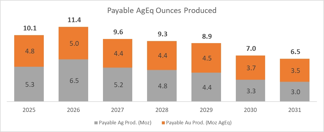
Source: Coeur, 2024.
Notes: The AgEq is based on Ag:Au ratio of 86.38:1, calculated using metal prices of $2,493 /oz Au and $28.86/oz Ag. All numbers are rounded.
| |
Figure 19‑2: | Ore Mining Schedule |

Source: Coeur, 2024.
| 19.3.2 | Metallurgical Recoveries |
Metallurgical recoveries were applied to the economic model in accordance with the metallurgical test work and the actual metal recoveries described in Section 10. The overall achieved LOM recoveries are shown in Table 19‑1.
| Table | 19‑1: LOM Processing Recoveries |
| Metal | Unit | Recovery |
| Gold | % | 98.0 |
| Silver | % | 97.5 |
| 19.3.3 | Freight, Smelting and Refining |
Assumed terms for smelting and refining of the gold and silver product are discussed in Section 16. Rates are based on the average historic payment terms and refining costs provided by the Company, which are to charges in the industry.
| 19.3.4 | Metal Prices |
The economic model is based on the following metal price assumptions:
Table 19‑2: | Metal Price Assumptions |
| Metal | Unit | 2025 | 2026 | 2027 | 2028 | 2029-LOM |
| Gold Price | $/oz | 2,700 | 2,550 | 2,500 | 2,450 | 2,400 |
| Silver Price | $/oz | 30.00 | 29.50 | 29.00 | 28.50 | 28.00 |
Base case metal prices selected for this report were based on a review of consensus price forecasts from banks and financial institutions, a three-year historic trailing average of spot prices, and current spot prices.
| |
| 19.3.5 | Operating Costs |
The operating costs are detailed in Section 18. The projected total operating costs are estimated to average $176.95/t processed. Mining costs are estimated to be $110.29/t processed ($114.17/t mined).
Table 19‑3: | LOM Operating Costs |
| LOM Average Operating Cost | ||
| Mining* ($/t processed) | 110.29 | |
| Process ($/t processed) | 42.05 | |
| G&A ($/t processed) | 24.61 | |
| Total LOM operating cost ($/t processed) | 176.95 |
Note: Includes stope development but excludes capitalized underground development.
| 19.3.6 | Capital Costs |
All initial construction capital costs have been incurred at Las Chispas Operation. Future capital costs are limited to sustaining capital costs, predominantly related to underground mine development and infrastructure, closure costs, management fees, and exploration planned for 2025. All mining related sustaining capital costs were estimated by the Company and scheduled to match the expected spend profile developed as part of the mining cost estimation process and based on the production and waste movement profile. Sustaining capital costs for the process plant, tailings facility and other surface infrastructure were scheduled based on projected capital expenditures.
An allowance of $11.9 M was made for closure and reclamation, based on an estimate developed and carried by the Company. The spending is scheduled to occur across ten years with a bulk of the spend occurring during the three years following the cessation of production (estimated to be 2032-2034). No provision or accrual for closure was made (cash or otherwise) for the purposes of the economic evaluation.
| |
Table 19‑4: | Sustaining Capital Cost |
| Area | Units | Sustaining Capital | |
| Mine & Underground Infrastructure | $M | 154.2 | |
| Process Plant | $M | 4.0 | |
| G&A and Other | $M | 4.9 | |
| Total | $M | 163.1 | |
| Closure | $M | 11.9 |
| 19.3.7 | Royalty |
There is a 2% royalty on the Nuevo Lupena and Panuco II concessions.
The royalty is subject to material that exceeds specified grade thresholds on these concessions. None of the estimated Mineral Reserves are within these concessions; therefore, this royalty is not applicable and was excluded from the economic analysis.
| 19.3.8 | Working Capital |
Working capital adjustments in the model include:
| • |
| • |
| • | Special Mining Duty: The model assumes that payments will be collected in the year after the costs are incurred. |
| • |
Current VAT and accounts payable balances have been updated to YE2024.
| 19.3.9 | Taxes and Government Royalties |
The corporate taxes and government royalties applied to this Report cash flow include the following:
| • | Corporate income tax of 30% |
| • | Special mining duty of 8.5% of EBITDA, applicable to mining companies |
| • | Extraordinary mining royalty of 1.0% of net revenue (NSR), applicable to gold and silver operations. |
These taxes were built into the financial model used for this evaluation and included in sensitivity analysis.
| |
| 19.3.10 | Closure Costs and Salvage Values |
An allowance of $11.9M was made for closure, an estimate developed by the Company in 2024 based on area of disturbance and mine life relative to other Mexican operations. The spending is scheduled to occur across ten years with the bulk of the spending occurring during the three years following the cessation of production (estimated to be 2032-2034). No provision or accrual for closure was made (cash or otherwise) for the purposes of the economic evaluation. Any change in regulations that would require the Las Chispas Operations to undertake progressive closure, or to post a cash bond, would affect the timing of these cash flows.
No salvage value was assumed for any items.
| 19.3.11 | Financing and Inflation |
No consideration of financing was made. The model considers the cash flow only at an asset level and assumes 100% equity ownership.
The modelling was undertaken in real Q4 2024 US$ with no inflation applied to either commodity prices or costs (unless otherwise stated). An assumption of US$ accounting was made.
| 19.4 | Financial Results |
The economic analysis demonstrates that the mine plan has positive economics under the assumptions used. The Las Chispas Operation post-tax (NPV) at a 5% discount rate is estimated to be $538.6M. A financial summary is shown in Table 19‑5.
Table 19‑5: | Economic Analysis Summary |
| Description | Unit | LOM Total/Avg. | |
| Average Mill Throughput | t/d | 1,250 | |
| Mine Life years | years | 7 | |
| Average Gold Mill Head Grade | g/t Au | 3.51 | |
| Average Silver Mill Head Grade | g/t Ag | 329.6 | |
| Average Silver Equivalent Mill Head Grade | g/t AgEq | 632.5 | |
| Contained Gold in Mine Plan | koz Au | 356.6 | |
| Contained Silver in Mine Plan | koz Ag | 33,516.4 | |
| Contained Silver Equivalent in Mine Plan | (koz AgEq) | 64,319.4 | |
| Average Gold Metallurgical Recovery | % Au | 98.0% | |
| Average Silver Metallurgical Recovery | % Ag | 97.5% | |
| Payable Gold | koz Au | 349.0 | |
| Payable Silver | koz Ag | 32,645.9 | |
| Payable Silver Equivalent | koz AgEq | 62,787.5 | |
| Average Full Year Annual Production (Years 1-5) | |||
| |
| Description | Unit | LOM Total/Avg. | |
| Gold | Au koz/yr | 53.1 | |
| Silver | Ag koz/yr | 5,259.1 | |
| Silver Equivalent | AgEq koz/yr | 9,843.7 | |
| Mining Cost | $/t mined | 114.17 | |
| Mining Cost | $/t processed | 110.29 | |
| Process Cost | $/t processed | 42.05 | |
| G&A Cost | $/t processed | 24.61 | |
| Total Operating Cost | $/t processed | 176.95 | |
| LOM Sustaining Capital Cost | $M | 163.1 | |
| Closure Costs | $M | 11.9 | |
| Cash Costs LOM – Mine Level | $/oz AgEq | 9.42 | |
| Au Price (LOM Average) | $/oz | 2,493 | |
| Ag Price (LOM Average) | $/oz | 28.86 | |
| Undiscounted LOM net free cash flow | $M | 626.4 | |
| Pre-Tax NPV 5%, $M | 5%, $M | 853.0 | |
| Post-Tax NPV (5%, $M) | 5%, $M | 538.6 |
The production schedule was incorporated into a financial model to develop the annual recovered metal production. The annual at-mine revenue contribution of each metal was determined by deducting the applicable treatment, refining, and transportation charges (from mine site to market) from gross revenue.
The cash flow is based on payable ounces of 349.0 koz gold and 32,645.9 koz silver.
Sustaining capital costs were incorporated on a year-by-year basis over the LOM, and operating costs were deducted from gross revenue to estimate annual mine operating earnings.
The financial model includes a mine closure and reclamation cost forecast of $11.9M. The spending is scheduled to occur across ten years with a bulk of the spend occurring during the three years following the cessation of production (estimated to be 2032-2034).
The operating costs are expected to average $176.95 per tonne milled over the LOM. Additional 2025 expensed exploration costs are included in the NPV calculation but are not required for current Mineral Reserves.
Table 19‑6 is an overall cost summary for the Las Chispas Operation.
| |
Table 19‑6: | Cost Summary |
| Item | LOM $M | Per AgEq Oz | |
| Mining | 348.8 | 5.56 | |
| Processing + TCRC | 151.8 | 2.42 | |
| G&A | 77.8 | 1.24 | |
| Cash Costs | 578.5 | 9.21 | |
| Sustaining Capital | 163.1 | 2.60 | |
| Closure | 11.9 | 0.19 |
Note: Inventory adjustments include costs applied to previously unsold ounces from inventory. Operating costs differ from cash costs.
Tax analysis was included in the financial model and in sensitivity analysis (refer to Section 19.3.9).
Figure 19‑3 shows the annual after-tax net cash flows (NCFs) and cumulative after-tax net cash flows.
The project is a mature producing and cash flowing asset and has already paid back it’s initial capital investment.

Source: Coeur, 2024.
| 19.5 | Sensitivity Analysis |
A sensitivity analysis was completed to evaluate the response of the NPV to changes in assumptions on key inputs of metals prices, sustaining capital costs and operating costs. The after-tax results across a range of ±20% from the base case assumption value are shown in Figure 19‑4. The Las Chispas Operation maintains a positive NPV across the range tested and is most sensitive to metal prices, with a smaller impact due to changes in operating and sustaining capital costs. Grade or recovery sensitivities match metal price sensitivity.
| |
Figure 19‑4: | Post-Tax NPV Sensitivities |

Source: Coeur, 2024.
Table 19‑7: | Post-Tax NPV($M) Sensitivities (base-case is bolded) |
| Parameter | -20% | -15% | -10% | -5% | Base | 5% | 10% | 15% | 20% | |
| Metal Price/Grade | 340 | 390 | 439 | 489 | 539 | 588 | 638 | 688 | 737 | |
| Operating Cost | 600 | 585 | 570 | 554 | 539 | 523 | 508 | 492 | 477 | |
| Capital Cost | 562 | 556 | 550 | 544 | 539 | 533 | 527 | 521 | 516 |
| 19.6 | Gold and Silver Price Scenarios |
A sensitivity analysis was performed to assess the impact of changing gold and silver prices on the Las Chispas Operation, as outlined in Table 19‑8. The base case is bolded in the table.
Table 19‑8: | Economic Results for Different Metal Price Scenarios |
| Price Case | Gold Price ($/oz) | Silver Price ($/oz) | Post-Tax NPV 5% ($M) | |
| Base Case (LOM average) | 2,493 | 28.86 | 538.6 | |
| Downside Case (Reserve Cutoff) | 1,800 | 23.50 | 308.9 | |
| Spot Case | 2,814 | 31.83 | 649.7 | |
| Upside Case | 3,000 | 35.00 | 742.0 |
Note: Spot Prices are based on data as of February 2nd, 2025. The Downside case is based on prices used to determine the mineral reserves cutoff.
| |
| 20 | ADJACENT PROPERTIES |
Advanced exploration or operating properties are not known to exist immediately adjacent, or contiguous to, the Las Chispas Property that have relevance to the Report.
| 20.1 | Nearby Properties and Operating Mines |
Many operating mines exist along the Rio Sonora valley in proximity to the Las Chispas Property. These include the nearby Santa Elena Mine, operated by First Majestic Silver Corp., and the Mercedes Mine, operated by Bear Creek Mining Corp. The Santa Elena Mine is a gold-silver underground mine, processing 2,500 t/d and is located 22 km south–southwest of Las Chispas (First Majestic, 2025). The Mercedes Mine is also a gold–silver underground mine, processing 2,000 t/d and is located 33 km to the northwest of Las Chispas (Bear Creek, 2025).
The mineral deposits being exploited at these mines are low to intermediate sulphidation epithermal veins with associated breccia and stockwork over varying thicknesses of <1 m to >10 m. The deposits occur in volcanic host rocks with similar age of precious metal emplacement (late Cretaceous to Paleogene Neogene) to Las Chispas. The gold–silver mineralization found on these properties is similar to Las Chispas in lithology, structural controls, alteration, and geochemistry with some variations. Current mining operations may differ from the Las Chispas Operation.
| 20.2 | Comment on Adjacent Properties |
The Qualified Person has been unable to verify the information above. The information is not necessarily indicative of the mineralization on the Las Chispas Property that is the subject of this Report.
| |
| 21 | OTHER RELEVANT DATA AND INFORMATION |
There is no additional relevant data or information that should be included in this Technical Report Summary.
| |
| 22 | INTERPRETATION AND CONCLUSIONS |
| 22.1 | Introduction |
The QPs note the following interpretations and conclusions in their respective areas of expertise, based on the review of data available for this Report.
| 22.2 | Mineral Tenure, Surface Rights, Water Rights, Royalties and Agreements |
Information from legal and Coeur experts support that the tenure held is valid and sufficient to support a declaration of Mineral Resources and Mineral Reserves.
The Las Chispas Operation consists of 27 mineral concessions, totalling 1,414 ha. Concessions have expiry dates from 2039 to 2073. LLA, a wholly-owned subsidiary of Coeur, has acquired 100% title to 25 of the mining concessions and is in control of the other two mining concessions. The mineral concessions that host the Mineral Resources and Mineral Reserves are in good standing. At the Effective Date of the Report, all required mining duties were paid.
There are three option agreements. Option 1 is for the La Fortuna mining concession applications No. 082/39410 and 082/38731, which cover the Panuco II and Carmen Dos Fracción II mineral lots; title transfer to LLA of the new concession are pending until the applications are issued as mining concessions. Under Option 2, LLA has a 67% ownership interest in the Lopez concession. Option 3 provides LLA with 100% rights to Panuco II, pending title for ownership. All three options are not material to the Report.
The surface rights overlying the Las Chispas mineral concessions and road access from local highway are either owned by LLA or held by LLA under negotiated lease agreements and sufficient to support plant operations.
A 2% royalty is payable to the Gutierrez-Pérez-Ramirez optionees, on the Nuevo Lupena and Panuco II concessions (when granted) for material that has processed grades of ≥0.5 oz/tonne gold and ≥ 40 oz/tonne silver, combined. No Mineral Reserves exist on these concessions.
To the extent known to the QP, there are no other significant factors and risks that may affect access, title, or the right or ability to perform work on the Las Chispas Operation that are not discussed in the Report.
| 22.3 | Geology and Mineralization |
Mineral deposits in the Las Chispas District are classified as low to intermediate sulfidation gold and silver epithermal systems.
The understanding of the vein settings, lithologies, mineralization, and the geological, structural, and alteration controls on mineralization is sufficient to support estimation of Mineral Resources and Mineral Reserves.
There is remaining exploration potential in the Las Chispas Operation area. A number of the known veins remain open along strike (e.g., Las Chispas Main) and at depth (e.g., Amethyst, Babi Main Babicanora Norte Veins). Surface geological mapping has identified several mineralized structures to the north of the Las Chispas Area that require further drill testing (e.g., Los Chiltepins, El Cumaro and Ranch Veins).
| |
| 22.4 | Exploration, Drilling and Analytical Data Collection in Support of Mineral Resource Estimation |
The exploration programs completed to date are appropriate for epithermal-style gold and silver mineralization.
Sampling methods are acceptable to support Mineral Resource estimation.
Sample preparation, analysis and security were generally performed in accordance with exploration best practices and industry standards at the time the information was collected.
The quantity and quality of the logged geological data, collar, and downhole survey data collected in the exploration and infill drill programs are sufficient to support Mineral Resource estimation.
No material factors were identified with the data collection from the drill programs that could significantly affect Mineral Resource estimation.
Sample preparation and analyses were performed by independent accredited laboratories. The sample preparation, analysis, and security practices and are acceptable, meet industry-standard practices at the time they were undertaken, and are sufficient to support Mineral Resource estimation.
QA/QC submission rates met industry best practices at the time of each of the drill campaigns. The QA/QC programs did not detect any material sample biases in the data reviewed that supports Mineral Resource estimation.
The data verification programs concluded that the data collected from the Las Chispas Operation adequately support the geological interpretations and constitute a database of sufficient quality to support the use of the data in Mineral Resource estimation.
| 22.5 | Mineral Processing and Metallurgical Testing |
Based on the assumptions and parameters presented in the Report, the Las Chispas Operation should continue to provide positive economics.
| 22.6 | Mineral Reserve Estimate |
Mineral Reserve estimation uses industry-accepted practices, and the estimate is reported using Subpart 229.1300 – Disclosure by Registrants Engaged in Mining Operations.
Mineral Reserves were converted from Measured and Indicated Mineral Resources and do not include any Inferred Mineral Resources. Inferred Mineral Resources contained within the Mineral Resource block models were treated as waste at zero grade.
Factors that may affect the Mineral Reserve Estimate include geological complexity, geological interpretation, and Mineral Resource block modelling; COG estimations; commodity prices, market conditions and foreign exchange rate assumptions; operating cost and productivity assumptions; sustaining capital costs to maintain production; rock quality and geotechnical constraints, dilution and mining recovery factors; hydrogeological assumptions; and metallurgical process recoveries. There are no other environmental, legal, title, taxation, socioeconomic, marketing, political or other relevant factors known to the QP that would materially affect the estimation of Mineral Reserves that are not discussed in the Report.
| |
| 22.7 | Mining Methods |
| 22.7.1 | Geotechnical Considerations |
Extensive geomechanical core logging and underground mapping has been completed by Las Chispas Operations at the Babicanora and Las Chispas Complexes using the RMR76 and Q’ rock mass classification systems. Rock mass structure data has been collected through mapping in the sill drives at the BAN, BAV, and BAM veins. The rock mass quality and structural data were reviewed by KP through site visits, core photos, and complementary underground mapping.
The available data have been used to define rock mass quality domains based on spatial variability, proximity to the mineralized zone, and lithology. The rock mass quality in the waste development and in the mineralized areas is typically GOOD (i.e., RMR76 values between 60 and 70). At the BAM and BAS veins, the rock mass quality in proximity to the mineralization is variable and can be of reduced quality (i.e., POOR to FAIR with RMR76 values between 20 and 60). The mineralization is hosted in a fault zone at the BAC vein, and the rock mass quality is typically POOR (i.e., RMR76 values between 20 and 35).
The available discontinuity orientation data have been used to define the structural domains that reflect differences between the veins as well as several key lithologies. The defined joint sets are parallel to sub-parallel to the mineralization, cross-cut the mineralization, and are sub-horizontal.
The following geotechnical design input was provided to the mine plan was based on the rock mass quality and structural domains, empirical stability analyses, 2D numerical modelling, existing experience at the mine, and experience from other similar projects and mines:
| • | Stope dimensions and overbreak |
| • | Dimensions for crown, sill, rib and inter-lode pillars |
| • | Offsets and strategies for mining around voids and historic workings |
| • | Offsets between stopes and development |
| • | Extraction sequencing |
| • | Strategies for temporary sill pillar recovery under sill mats |
| • | Ground support |
| 22.7.2 | Hydrological Considerations |
The new mine plan at the Las Chispas Operation implies some of the workings to be eventually submerged below the water table; dewatering will therefore be required. Even if hydrogeological studies completed so far indicate there is no major concerns related to groundwater additional information will be required to define the exact inflow to support the dewatering strategy. When mine development gets closer to the water table, further analysis will be completed to refine the assumptions used in this Report. Those will include drilling from underground in various areas and testing open boreholes from underground.
| |
| 22.7.3 | Mining Methods |
The mine design was based on a targeted production rate of 1,250 t/d. The proposed underground mining approach will use variations of longhole stoping and cut and fill mining methods via several access drifts and ramps. These methods are appropriate to the sub-vertical vein geometry, where the veins have thicknesses ranging from 0.1–10 m.
Mining operations will extract from the principal veins divided into six mining areas, which will be accessed via three portals. Each mining area will be serviced by supporting infrastructure including power distribution, compressed air distribution, water supply, ventilation, dewatering and communications.
The equipment fleet is conventional for underground mining operations.
All mining activities are being completed by a contractor. Geological, grade control and planning services are being provided by Las Chispas Operations. The contractor will supply adequate underground mining equipment for the different mining activities.
| 22.8 | Recovery Methods |
The Process Plant originally designed for 1,250 t/d with an estimate rate of milling of 57 t/h (tonne per operating hour) and a 91.3% availability.
The plant has been operating without the flotation circuit. The cyanide detox system has been retrofitted to operate on pond seepage solution as well as leach slurry and has been proven effective.
Overall, the Process Plant has operated according to the design criteria and met or exceeded throughput and availability targets. For the LOM, it is reasonable to expect that the Process Plant will be able to process the expected mine production to mill of 1,250 t/d at a metallurgical recovery of 98.0% for gold and 97.5% for silver.
| 22.9 | Project Infrastructure |
The Operation includes the following infrastructure: underground mine, including portals and ramps; various roads such as the main access road to site, borrow pit haul road, FTSF haul road, WRSF haul road, and explosives access road; diversion and collection channels, culverts, and containment structures; site main gates and guard houses; accommodation camp; warehouse and truck shops, offices, medical clinic, and nursery; explosives magazines, exploration core shack; Process Plant; control room; doré room; assay laboratory (off-site facility); reagent storage facilities; water treatment plant; stockpiles and WRSFs; FTSF; hazardous waste containment facility; and Nuclear Devices warehouse.
Electrical power is supplied to site from the national grid, by way of a 33 KV overhead power line. Emergency power is also available throughout the property.
Water is being sourced from the Underground and from the Sonora valley.
| |
| 22.10 | Markets and Contracts |
Gold and silver doré can be readily sold on many markets throughout the world and the market price ascertained on demand. Las Chispas Operation doré is delivered to the refinery, where it is refined under a fixed-term contract. After refining, gold and silver are sold on the spot market to arm’s length international metal brokers and institutional banks. The existing contract for refining and with metal brokers and banks is considered within industry standards. The commercial terms are reviewed at the renewal period and the company does not expect any difficulties with renewing the existing contract or securing new contracts for the sale of the doré.
At the Report Effective Date, the Company has entered into all contracts necessary for operating Las Chispas. These contracts and agreements include, but are not limited to, contracts for drilling, underground mining, explosives, power, supply of consumables, catering and camp management, security, personnel transportation and refining (as per above). These contracts are reviewed and negotiated periodically to ensure they remain competitive and aligned within industry norms for projects in similar settings in Mexico.
Metal pricing used in the economic analysis is based on consideration of various metal price sources. This included review of consensus price forecasts from banks and financial institutions, three-year trailing average of spot prices, and current spot prices.
| 22.11 | Environmental Studies, Permitting and Social Considerations |
| 22.11.1 | Environmental Considerations |
Environmental surveys and studies for the Las Chispas Operation were completed in support of permit applications. Completed studies include climate, flora, fauna, air quality, noise, surface and groundwater quality.
Based on the 2023 ESG report (Silvercrest 2023 ESG Report, 2024), ML testing showed that potentially leachable metals included barium and lead, but in concentrations that were below the maximum allowable limits. ARD testing indicated that the majority of the rocks showed low ARD potential. The majority of tailings samples showed non-acid forming (NAF) characteristics in NAG testing.
No known environmental liabilities exist in the Las Chispas Operation are from historic mining and processing operations. Soil and tailings testing were conducted as part of the overall sampling that has been ongoing at site. To date, there are no known contaminants measured in the soils. Water quality testing is currently ongoing through ongoing environmental studies.
| 22.11.2 | Permitting Considerations |
LLA has a permitting team in Mexico located at the Las Chispas Operation. The permitting team is in charge of monitoring all LLA obligation pertaining to its existing permits, including the data acquisition and reporting obligations. The permitting Team is also monitoring potential regulatory changes in Mexico and mandated to respond to such potential changes to permits if and when required. The Permitting Team is supported with Mexican Legal Counsel.
LLA now operates under the umbrella of a LAU (Licencia Ambiental Unica) which is an integrated permit for all of its operation as related to atmospheric conditions at the Las Chispas Operation. Permits will be renewed as required.
| |
| 22.11.3 | Closure and Reclamation |
A Conceptual Closure Plan was prepared in general accordance with applicable Mexican standards. Under Mexican law, mining may be initiated under a Conceptual Closure Plan with a Detailed Closure Plan being developed later in the project life.
The closure cost forecast is $11.9M. Closure costs were assumed to be disbursed over a period of approximately three years, following cessation of production.
| 22.11.4 | Social Considerations |
A social baseline study, completed in 2019–2020, found key areas of community concern were: water usage, and water safety; a lack of information on the Las Chispas Operation; concerns around an environmental incident in 2014 that was caused by a different mining company (100 km from the Las Chispas Operation); a desire to see improvements in the local infrastructure; that environmental safety and appropriate mine closure protocols should be in place to protect the region at the end of the LOM; and job creation with a focus on opportunities being made available for women.
A 2019–2020 materiality assessment as well as a climate risk assessment in 2021 formed the basis of a company-wide Environmental and Social Management System. Key findings from the materiality and climate risk assessments were centered around climate (drought, extreme heat, flooding) and water risks (economic reliance on access to water), community health issues (poor sewage), environmental safety of the local river and agriculture, employment opportunities, a desire for improved infrastructure (aqueducts, sports, recreation, health) and a concern regarding a potential influx of people from outside the community taxing local infrastructure.
A Five-year Water Stewardship Plan has been formalized, aiming at improving the local infrastructure which will provide improved economic resilience for the large percentage of the community that relies on farming and ranching. In conjunction with the local infrastructure projects, A communication strategy has been implemented that employs direct outreach, social media, company-generated videos, flyers, posters and workshops. There is also a whistle blower policy and hotline and a grievance mechanism process.
| 22.12 | Capital and Operating Costs |
| 22.12.1 | Sustaining Capital Cost Estimates |
Capital cost estimates are at a minimum at pre-feasibility level of confidence, having an accuracy level of ±25% and a contingency range not exceeding 15%.
LOM sustaining capital costs a total of $163.1M, which can be broken down as per Table 22‑1.
| |
Table 22‑1: | LOM Sustaining Capital Cost Estimates ($M) |
| Calendar Year | LOM | 2025 | 2026 | 2027 | 2028 | 2029 | 2030 | 2031 | |
| Production Year | 1 | 2 | 3 | 4 | 5 | 6 | 7 | ||
U/G Mine Development ($M) | 139.3 | 30.6 | 31.4 | 29.8 | 20.6 | 15.1 | 11.8 | - | |
U/G Mine Infrastructure ($M) | 14.9 | 3.8 | 6.1 | 1.7 | 2.1 | 1.2 | - | - | |
Process Plant ($M) | 4.0 | 1.9 | 0.5 | 0.5 | 0.5 | 0.5 | - | - | |
Other Sust. & Dev. ($M) | 0.6 | - | - | - | 0.3 | - | 0.3 | - | |
G&A (including mobile) ($M) | 4.3 | 1.1 | 0.8 | 0.8 | 0.8 | 0.8 | - | - | |
| Total | 163.1 | 37.5 | 38.8 | 32.8 | 24.3 | 17.6 | 12.1 | - |
| 22.12.2 | Reclamation and Closure Cost Estimates |
An allowance of $11.9M was made for closure costs with spending scheduled to occur across ten years with the bulk of the spend occurring during the first three years following the cessation of production. Any change in in project scope or regulations would require the company to update the total cost and timing of these expenditures.
No salvage value was assumed for the plant and surface infrastructure. It has also been assumed that CFE would accept ownership of the power line which is common in Mexico.
| 22.12.3 | Operating Cost Estimate |
Operating cost estimates are at a minimum at pre-feasibility level of confidence, having an accuracy level of ±25% and a contingency range not exceeding 15%.
The average LOM operating cost is estimated at $176.95/t processed. The operating cost is defined as the total direct operating costs including mining, processing, and G&A costs. Mining costs are estimated to be $110.29/t processed ($114.17/t mined). Tonnes of material to be processed includes mined ore that is already in stockpiles. Table 25-2 shows a summary breakdown of the operating costs for the entire LOM.
Table 22‑2: | Operating Cost Summary |
| Area | LOM Average Operating Cost ($/t processed) |
| Mining | 110.29 |
| Process | 42.05 |
| G&A | 24.61 |
| Total LOM Operating Cost ($/t processed) | 176.95 |
| 22.13 | Economic Analysis |
A pre- and post-tax economic analysis was completed on the basis of a discounted cash flow model featuring a 5% discount rate. The analysis used constant (real) Q4 2024 US$ and the Las Chispas Operation cash flows were modelled in annual periods.
| |
The model assumed a production period of seven years, including 2025-2031.
The economic model was based on an average gold price of $2,493/oz and a silver price of $28.86/oz. The refining terms used as the basis of the economic analysis are based on actual average cost paid by the Company with its third-party refiner. The freight terms are also based on actual rates.
Taxes were built into the financial model and include a 30% corporate income tax, a mining tax of 8.5% of EBITDA, and a precious metals mining tax on 1% NSR.
The economic analysis demonstrates that the mine plan has positive economics under the assumptions used. The Las Chispas Operation post-tax (NPV) at a 5% discount rate is estimated to be $538.6M. A summary of the economic analysis of the Las Chispas Operation is shown in Table 19‑5.
The Las Chispas Operation is most sensitive to metal pricing and recovery/grade. Grade sensitivity mirrors the sensitivity to metal prices.
| 22.14 | Risks and Opportunities |
| 22.14.1 | Risks |
| 22.14.1.1 | Exploration, Drilling and Analytical Data Collection in Support of Mineral Resource Estimation |
A structured risk management process was established to promote early identification of risks, determine the likelihood and consequence of risk actualization, and propose risk mitigation plans to reduce the likelihood and (or) impacts. The same process was used to identify and promote opportunities.
| 22.14.1.2 | Metallurgical Testwork and Recovery Plan |
There is a minor risk that Au and Ag recoveries while processing future ore do not meet current estimated recoveries. However, the flexibility of the Process Plant design will provide opportunities to mitigate losses in recovery.
| 22.14.1.3 | Mineral Resource Estimate |
The drill sample spacing varies by vein and the classification of Mineral Resource Estimate was assigned based on the level of confidence based on drill core sample spacing and grade variability. Risk is associated with all classifications of Mineral Resource Estimate, most particularly with the Inferred Mineral Resource Estimate.
There is a risk that the Mineral Resource Estimate wireframes (>150 g/t AgEq) may be moderately high biased with respect to the representative volume, and subsequent estimated tonnage and metal content. This potential bias could be where the wireframes extend somewhat too far into lower-grade (<150 g/t AgEq) assay areas of influence. A follow-up rolling reconciliation is recommended to allow for any mine call factor adjustments to be made in these lower-grade areas.
Localized high-grade samples were encountered in drill core sampling as part of the mineralization system. Locally, this represents a risk in the accuracy of grade estimation for Mineral Resource and subsequent Mineral Reserve estimation, and to operational grade control.
Where only widely spaced sampling is available, the spatial extent of the high-grade mineralization may be uncertain. This risk can be reduced through future close-range sampling to delineate high-grade shoots within the vein systems, thereby allowing the highest-grade material to be sub-domain to constrain spatial influence of these samples within delineated shoots. Closely spaced pre-production definition drilling in combination with duplicate sampling protocols for high-grade samples should be implemented to mitigate excessive extrapolation of high-grade values and to inform the local, short-range, grade variability.
| |
| 22.14.1.4 | Mineral Reserve Estimate and Mine Plan |
General factors that may affect the Mineral Reserve Estimate include adjustments to gold price and exchange rate assumptions; changes in operating and capital cost estimates; dilution adjustments; changes to geotechnical assumptions, changes to hydrogeological and underground dewatering assumptions; and changes to modifying factor assumptions, including mining recovery and dilution. Additionally, adjustments to reserve estimates may be required if reserve to plant production reconciliation trend in a consistently bias manner (currently F3 is 0.95) over successive reserve estimations.
There is a known open stope area in the Babicanora Central zone. This area could cause recovery problems because although the general area is known, the exact size and geometry of the open stope is not appropriately defined. To mitigate the possible impact of this risk, all mining within 10 m of the known void have been removed from the plan, and test hole drilling cost estimates were included in the costing of this area.
Las Chispas Operations has established access to the historic workings at the historic Las Chispas Area and has created a 3D model of the extensive workings, through the use of digitized historic long sections. However, there remains considerable uncertainty in the position of some of the voids. It is recommended that surveys be completed to confirm the void position and geometry prior to further mining. Probe drilling will also be required on advance during development near potential voids.
| 22.14.6.5 | Project Infrastructure |
| 22.14.6.5.1 | Filtered Tailings System Facility (FTSF) |
Based on tailings filtering assays (Outotec, 2020) a portion of the tailings could show high clay/mica content, which could only be dewatered in the filter plant to a 22% gravimetric moisture content, which is above the range of optimum compaction contents determined from geotechnical laboratory testing. This could translate into greater moisture than the target at the filter plant, and longer times and greater effort to process and compact the filtered tailings at the FTSF.
This risk has not materialized to date. However, this potential risk can be further mitigated by providing sufficient area for the FTSF, where tailings that do not meet the design specifications or higher clay content tailings can be temporarily placed in the interior portion of the FTSF. Filtered tailings can then be extended and compacted when conditions allow, without the need to stop tailings disposal.
Additional tailings storage (Phase 2) capacity was constructed in 2024 to address the scenario of higher clay content tailings being produced staring.
| 22.14.2 | Opportunities |
The following sub-sections summarize opportunities that could potentially improve on the economics of this Report. Alone or combined, these opportunities could change the approach to development, timelines, capital requirements and operating costs described within this Report with potential to change production, scale, economics and (or) the Las Chispas Operation value.
| |
| 22.14.2.1 | Exploration and Mineral Resources |
Several potential opportunities have been identified for expansion and increasing confidence of existing Mineral Resources, in addition to brownfields exploration to test defined targets along vein strike and to depth.
The most significant upside is the potential for:
| • | Conversion of Inferred Mineral Resources to Indicated Resources through infill drilling; and |
| • | Discovery of additional mineralization through exploration and exploration drilling that may support Mineral Resource estimation. |
The 2025 drill program should also focus on identifying additional Inferred Mineral Resources and to improve confidence of existing Inferred to the level of Indicated Mineral Resources. Work will consist of infill and Inferred drilling and brownfields exploration drilling to test mapped targets along vein strike and to depth.
| 22.14.2.2 | Mineral Resource Estimate |
Several potential opportunities have been identified for expansion and increasing confidence of existing Mineral Resources, in addition to brownfields exploration to test mapped targets along vein strike and to depth.
The most significant upside is the potential for conversion of existing Inferred Mineral Resources to Indicated Mineral Resources with additional drilling, and the exploration potential to identify and support new Inferred Mineral Resources.
Inferred Mineral Resources are estimated at 1.2 Mt grading 3.81 g/t Au, and 268 g/t Ag, or 571 g/t AgEq, for 21.5 Moz AgEq. The majority of the AgEq oz are of sufficient mining width, close to surface, and in proximity to current or planned underground workings, and should be targeted immediately for drilling to assess conversion into Indicated Resources. The majority of these Mineral Resources are located in the El Muerto Splay, Babicanora Norte, Babi Sur and Sorpresa Zone.
The Las Chispas Operation has significant brownfields exploration potential. There are over 23 km in strike of underexplored veins and structures throughout the property that have been identified on surface through mapping and sampling programs. These areas include the Chiltepin Area, La Martina, Las Chispas Southeast, Ranch Vein, and La Victoria Vein. There are also several blind veins and structures that have been tagged through various drill programs including potential vein expansion to depth along several of the currently known zones. Future drilling should focus on step-out drilling within the known mineralization zones and testing deeper host lithologies, parallel veins and newly identified areas that had limited historical workings.
| 22.14.2.3 | Conversion of Inferred Mineral Resources |
Inferred Mineral Resources are estimated at 24.1 Moz AgEq (refer to Table 14-17). There are 15 Moz over 500 g/t AgEq with sufficient mining width, close to surface, and in proximity to current or planned underground workings, of which 10 Moz AgEq will be targeted immediately for drilling to assess conversion into Indicated Resources. A majority of these resources are located as follows.
BAS Area (BAS Main, BAS HW, BAS FW) has an estimated 7.31 Moz AgEq with a grade of 566 g/t AgEq (4.55 g/t Au and 204 g/t Ag) in Inferred Mineral Resources. Included in this amount is 4.86 Moz AqEq with a grade of 1,050 g/t AgEq (8.46 g/t Au and 378 g/t Ag) using a cut-off of 500 g/t AgEq. This mineralization is located proximal of the current ongoing underground development and proposed mine design for the BAS Main Vein. Encouraging high grade mineralization has been intercepted both at depth and towards surface in the main mineralized structures indicating a potential for expansion of mineralization.
| |
El Muerto Area (El Muerto, El Muerto Splay, Los Parientes) has an estimated 3.42 Moz AgEq with a grade of 711 g/t AgEq (4.38 g/t Au and 362 g/t Ag) in Inferred Resources. This includes El Muerto Splay which contains 2.15 Moz AgEq with a grade of 1,148 g/t AgEq (6.62 g/t Au and 622 g/t Ag) using a cut-off of 500 g/t AgEq. Drilling of the El Muerto Zone at depth below the Babicanora Central Zone has potential to intercept additional high-grade mineralization below the limit of the current Mineral Resource Estimate.
BAN Area (BAN Main, BAN NW Ext., BAN HW, BAN Splay 1-4) has an estimated Inferred Mineral Resource of 3.44 Moz AgEq with a grade of 785 g/t AgEq (3.54 g/t Au and 503 g/t Ag). Included in this is BAN NW Extension with 1.55 Moz AgEq with a grade of 2,294 g/t AgEq (11.08 g/t Au and 1,413 g/t Ag) using a cut-off of 500 g/t AgEq. Expansion drilling along the projected NW strike of BAN Main has suggested the mineralized trend continues along strike and to surface in the area.
BAV Area (BAV Main, BAV FW, BAV Splay 1-3, BAV Andesite) has an estimated Inferred Resource of 2.43 Moz AgEq with a grade of 1,337 g/t AgEq (10.72 g/t Au and 484 g/t Ag). This includes BAV FW with 1.08 Moz AgEq with a grade of 2,327 g/t AgEq (14.00 g/t Au and 1,214 g/t Ag) using a cut-off of 500 g/t AgEq. Underground development in the BAV Main area has intercepted the BAV FW. Drilling underground with short, targeted holes may support potential for conversion of Inferred Mineral Resources to Indicated Mineral Resources.
Encinitas has an estimated Inferred Mineral Resource of 1.25 Moz AgEq with a grade of 567 g/t AgEq (6.51 g/t Au and 49 g/t Ag). Included in this amount is 898 Koz AgEq with a grade of 902 g/t AgEq (10.45 g/t Au and 72 g/t Ag) using a cut-off of 500 g/t AgEq. Located in the BAS Area, Encinitas has potential for mineralization along strike and to depth. Further step-out drilling along trend has potential for additional Inferred Mineral Resources.
Las Chispas Area (Las Chispas Main, Gio Mini, Luigi, Luigi FW, and excluding William Tell) has an estimated Inferred Resource of 2.25 Moz AgEq with a grade of 529 g/t AgEq. This includes Las Chispas Main Vein which contains 1.24 Moz AgEq with a grade of 1,783 g/t AgEq (8.66 g/t Au and 1,095 g/t Ag) using a cut-off of 500 g/t AgEq. This mineralization is along trend of current proposed mine design for the Las Chispas Main Vein and is open along strike and to depth which makes it a target for potential Mineral Resource expansion.
| 22.14.2.4 | Mine Design and Schedule Optimization |
The design of the LOM was completed at a level of detail sufficient for inclusion in this Report. The LOM plan will be used to form the basis of future detailed design and schedule. As with any LOM, there exists an opportunity to further improve the mine design and schedule in terms of detailed design, especially with due regard to integration of services, layout of development, design of stopes and geomechanics. The benefit from this additional work is estimated to be in the order of 5M AgEq ounces.
Geomechanical assumptions and assessments present opportunities to reclaim AgEq ounces in the following areas:
| • | The collection of additional data to reassess crown pillars, potentially reducing their size. |
| • | Longhole stopes under sill pillars are currently planned to be left empty with the use of rib and/or sill pillars. The addition of top sills in these stopes could result in an increase in recovery of these pillar at the cost of more development. |
| |
| • | Detailed design and sequencing of interlode pillars could add a few stopes where vein splays, the FW vein or HW vein are in close proximity to each other and the main veins. |
| • | Evaluate longhole stoping in areas of BAS at reduced sill heights improving cost and productivity. |
Additional opportunities to reclaim AgEq ounces through detailed design and site testing exist in the following areas:
| • | There is opportunity to review Measured and Indicated Resource which did not make the cut-off grade of after the first pass incremental MSO stope run. Some of this resource exists on the fringes of Mineral Reserve shapes and some exists as isolated material. More detailed design, such as varying stope widths, heights and strike lengths, could increase the mined grade of some of the fringe resource. In some cases, the isolated material could be bolstered with additional material converted during the exploration program. Site continues to work on improving blast design and wall control, which could allow for reductions in minimum mining widths and unplanned dilution. |
| • | Cut and fill and resue mine areas have the potential for conversion to longhole stoping where ground conditions are suitable. Converting these stopes to longhole provide a more robust and efficient mine plan with a reduced cost per tonne with an acceptable impact to dilution. |
| • | The Las Chispas Operation is currently trialing the Avoca variant of longhole open stoping. If trials are positive, Avoca could provide a cheaper and more productive method to apply in specific areas over the LOM. |
| • | Opportunity exists with development and infrastructure optimization of the ventilation network through detailed design, calibrating the LOM plan to the short-term site plan, optimizing the placement of fresh and return air raises to limit development and improve the overall circuit. |
| 22.14.2.5 | Recovery Plan |
Although the Process Plant has been built at a capacity of 1,250 t/d, it is designed to accommodate a future expansion of up to 1,750 t/d. Additional studies and engineering would be required to execute a future plant expansion, including a review of the crushing, grinding, flotation, leaching and dewatering circuits as well as power supply facilities.
| 22.14.6.6 | Project Infrastructure |
| 22.14.2.6.1 | Solar Power |
The project is engaged with outside consultants to examine the possibility of using renewable energy to meet operational needs. The broader geographic region is well suited for solar power and the company is actively pursuing a power purchase agreement from a solar supplier.
| |
| 23 | RECOMMENDATIONS |
| 23.1 | Introduction |
A sequential phase approach is presented for recommended future work. The following Table presents the budget for the recommended exploration and development activities to be completed in 2025.
| Table 23‑1: | Summary of Budget for Recommended Exploration and Development Activities |
| Exploration and Development Activity | Cost Estimate ($M) 2025 | |
| Exploration and Mineral Resource Conversion Drilling (74,800 m) | 14.50 | |
| QA/QC | 0.10 | |
| Bulk Density Investigation | 0.03 | |
| Resource Estimation | 0.10 | |
| Mine Design | 0.10 | |
| Sub-Total | 14.80 | |
| Contingency (10%) | 1.50 | |
| Total | 16.30 |
Note: Numbers may not add due to rounding.
| 23.2 | Exploration at Las Chispas |
Approximately 74,800 m of drilling is recommended, of which 18,800 m would be allocated to infill drilling, 30,400 m to Inferred Mineral Resources drilling and 25,600 m to exploration (discovery) drilling. Specific collar locations have yet to be determined. Successive drill collar locations will be dependent on the results of each drilled hole. The program budget assumes 60,000 to 90,000 samples will be taken and submitted for assay.
The infill and Inferred drilling should immediately target the higher-grade, close to current and future underground workings Inferred Mineral Resource. Areas where Indicated Mineral Resources did not make it into the updated Mineral Reserve are also considered in this phase. Other areas for future consideration should be included in future drilling phases. Exploration drilling should be planned for the Los Chiltepins veins, Las Chispas Northwest, Babicanora Norte SE, Los Sheiks, and Las Chispas Extension (eg. GAP zone) Babicanora Sur Deep, and follow-up on high-grade blind vein intercepts.
Surface exploration surveys should include additional geological and structural mapping and mineralogical and alteration studies, along with interpretation of intrusion age dating to refine the overall geological model and to aid identification of prospective deep targets.
The budget for the recommended Las Chispas Operations geology and exploration program is $16.3M (Table 23‑1). This budget is subject to modification, if warranted by the results of previous drilling programs. The recommended program should be completed in 2025.
| |
| 23.3 | QA/QC |
The sample preparation, analysis, and security procedures implemented at Las Chispas are consistent with standard industry practices. Since further drilling at the Las Chispas Operation is being undertaken to further define, increase confidence and expand on the current resources, the following is recommended:
| • | Continue insertion of all QC sample types (CRMs, blanks and duplicates) at the current rate of insertion for all sample types being collected; |
| • | Ensure that custom CRMs are suitably prepared, round-robin tested and span appropriate grade ranges; |
| • | Progressively phase out externally sourced CRMs when transitioning to custom CRMs, to enable the lab(s) time to adjust to new CRMs; |
| • | Continue real-time review and assessment of QC samples as results are received and follow-up on any issues immediately; |
| • | Continue re-analyzing 10 samples below and 10 above CRM failures in zones of significant mineralization, recording follow-up actions taken; and |
| • | Routinely umpire assay at least 5% of samples assayed at primary lab. |
The costs of this work program are estimated to be $100,000.
| 23.4 | Mineral Resource Estimation |
Prior to the next Mineral Resource update, the following work is recommended to be completed:
| • | Create a density model (instead of a uniform density of 2.55) with the existing density measurements (~45,000). Note that many of the bulk density measurements are not in the vein/alteration zone(s) and that the presence of cavities should also be considered if this work were to proceed. |
| • | Continue to use results of reconciliation, geometallurgical study, and underground development to optimize the geological model and grade estimation procedure. |
| • | Review the results of the Mine Reserve reconciliation process to identify opportunities to improve long range modelling and estimation methods, particularly to refine interpretation of ultra-high-grade ore shoots and to refine the geometry of mineral boundaries along strike, and |
| • | Consider the use of a minimum wireframe constraining width. |
| 23.5 | Mine Design |
Through calibration of the long-term mining plan to the short-term site plan, several opportunities exist for optimizing ramp placement, raise locations, and other infrastructure. This has the potential to reduce capital development and power requirements for fixed equipment.
It is recommended that alternative dewatering pumps be studied to reduce or eliminate the need for settling sumps. Helical rotor style pumps that are designed to pump clean and dirty (up to 5% solids) water are a low maintenance alternative to submersible pumps. Additionally, with the removal of settling sumps, there is no need to utilize LHDs to clean the sump, allowing the equipment and personnel to focus on mining activities.
| |
Due to the predominantly very narrow width of ore veins, the Mineral Reserve contains a total dilution of 166%, where 57% is unplanned dilution (or ELOS) and the remainder is internal dilution. Continuation of the ongoing work to improve drill and blast practices, ensuring timely extraction of blasted material, and prompt backfilling can all assist in reducing unplanned dilution. For the reduction of planned dilution, testing narrower minimum mining widths is recommended.
Sublevel spacing of 18 m for longhole open stoping could be increased with the introduction of more sophisticated drilling rigs. Hole deviation can be controlled with a more rigid drill, minimizing the impact of increased hole lengths.
Survey of the Las Chispas historic workings and stopes should be completed before production operations begin in this area.
| 23.6 | Metallurgy and Process Recovery |
The Las Chispas Operations are preforming at or above design values. It is recommended that the Operation continue to apply best practice actions to reduce the soluble metal losses and costs. Other than ongoing operational application of these practices, there is no cost to this work program.
| |
| 24 | REFERENCES |
Aguirre-Díaz, G., and McDowell, F., (1991). The volcanic section at Nazas, Durango, Mexico, and the possibility of widespread Eocene volcanism within the Sierra Madre Occidental: Journal of Geophysical Research, v. 96, p. 13,373–13,388.
Aguirre-Díaz, G., and McDowell, F., (1991). The volcanic section at Nazas, Durango, Mexico, and the possibility of widespread Eocene volcanism within the Sierra Madre Occidental: Journal of Geophysical Research, v. 96, p. 13,373–13,388.
Aguirre-Díaz, G., and McDowell, F., (1993). Nature and timing of faulting and synextensional magmatism in the southern Basin and Range, central-eastern Durango, Mexico: Geological Society of America Bulletin, v. 105, p. 1435–1444.
Alaniz-Alvarez and Nieto-Samaniego, A.F., (2007). the Taxco-San Miguel de Allende fault system and the Trans-Mexican Volcanic Belt: Two tectonic boundaries in central Mexico active during the Cenozoic, in Alaniz-Alvarez, S.A and Nieto-Samaniego, A.F., ed., Geology of Mexico: Celebrating the Centenary of the Geological Society of Mexico: Geological society of America special Paper 422, p. 301-316.
An Introduction to Cut-Off Grade Estimation, Second Edition. Society for Mining, Metallurgy, and Exploration, Inc.; January 2014, 159p.
Barr, James and Huang, Jianhui (John), (2019). Technical Report and Mineral Resource Estimate for the Las Chispas Property, Sonora, Mexico. Completed for SilverCrest Metals Inc. Effective date February 8, 2019.
Barr, James, (2018), Technical Report and Mineral Resource Estimate for the Las Chispas Property Sonora, Mexico. Completed for SilverCrest Metals Inc. Effective date February 12, 2018. Amended date May 9, 2018.
Bear Creek Mining Corporation. (2024). www.bearcreekmining.com/projects/mercedes. January 24, 2025
Buchanan, L.J., (1981). Precious metal deposits associated with volcanic environments in the southwest: in Relations of Tectonics to Ore Deposits in the Southern Cordillera: Arizona Geological Society Digest, v. 14, p. 237-262.
Carlos M. González-León, Luigi Solari, Jesús Solé, Mihai N. Ducea, Timothy F. Lawton, Juan Pablo Bernal, Elizard González Becuar, Floyd Gray, Margarita López Martínez, and Rufi no Lozano., (2011). Stratigraphy, geochronology, and geochemistry of the Laramide magmatic arc in north-central Sonora, Mexico. Geosphere; December 2011; v. 7; no. 6; p. 1392–1418.
Carlos M. González-León., Víctor A. Valencia., Margarita López-Martínez., Hervey Bellon., Martín Valencia-Moreno., and Thierry Calmus, (2010). Arizpe sub-basin: A sedimentary and volcanic record of Basin and Range extension in north-central Sonora, Mexico. Revista Mexicana de Ciencias Geológicas, v. 27, núm. 2, 2010, p. 292-312.
Caterpillar (2018). Caterpillar Performance Handbook. Peoria, Illinois, USA. 48th Edition.
Colombo, F., (2017a). Petrographic Report on 24 Rock Samples from Las Chispas district, Sonora, Mexico for SilverCrest Metals Inc. Internal report for SilverCrest Metals Inc., December 1, 2017, p. 1-71.
| |
Colombo, F., (2017b). Petrographic Report on Eight Rock Samples from Las Chispas district, Sonora, Mexico for SilverCrest Metals Inc. Internal report, Oct 31, 2017, pp 1-17.
Dahlgren, C.B., (1883). Historic Mines of Mexico: a Review of the Mines of that Republic for the past Three Centuries, p 81-82.
Delgado-Granados, H., Aguirre-Diaz, G.J., Stock, J.M., (2000). Cenozoic Tectonics and Volcanism of Mexico, Geological Society of America Special Paper 336, 278 pages.
Dufourcq, E.L., (1910). Minas Pedrazzini Operations near Arizpe Sonora, Engineering and Mining Journal, vol 90, p 1,105, December 3, 1910.
Dufourcq, E.L., (1912). Chispas Cyanide Plant, Arizpe, Sonora, Columbia University, The School of Mines Quarterly, vol 33, p 18, 1912.
Ferrari, L. Valencia-Moreo, M., Bryan, S., (2007). Magmatism and tectonics of the Sierra Madre Occidental and its relation with the evolution of the western margin of north America, p. 1-29; in Geology of Mexico: Celebrating the Centenary of the Geological Society of Mexico, The Geological Society of America, Special Paper 422, 2007, edited by Susana A. Alaniz-Alvarez and Angel F. Nieto-Samaniego; 465pp.
Fier, N. Eric, (2018). Technical Report and Updated Mineral Resource Estimate for the Las Chispas Property Sonora, Mexico. Effective date September 13, 2018.
First Majestic Silver Corp. (2024). www.firstmajestic.com/projects/overview/producing-mines/santa-elena. January 24, 2025.
First Majestic Silver, (2018). Annual Information Form (AIF) for the Year Ended December 31, 2017, report dated March 29, 2019.
Gonzalez-Becuar Elizard., Efren Perez-Segura., Ricardo Vega-Granillo., Luigi Solari., Carlos M. Gonzalez-Leon, Jesus Sole., and Margarita Lopez Martinez., (2017). Laramide to Miocene synextensional plutonism in the Puerta del Sol area, central Sonora, Mexico. Revista Mexicana de Ciencias Geológicas, vol. 34, number. 1, March, 2017, pp. 45-61.
Hard Rock Miner’s Handbook, Edition 5, Stantec Consulting Ltd. January 2014, 314p
Hartman, Howard L. (1992). SME Mining Engineering Handbook. 2nd ed. Littleton, Colorado: Society for Mining, Metallurgy, and Exploration, 1992. Print
Hydro-Ressources Inc, (2020). Las Chispas Mine – Hydrogeological Feasibility Analysis. 12p.
Hydro-Ressources, (2020). Las Chispas Mine Hydrogeological Feasibility Analysis, Technical Report – File P19-120, Hydro -Ressources Inc., November 2020.
Johnson, C. M., (1991). Large-scale crust formation and lithosphere modification beneath middle to late Cenozoic calderas and volcanic fields, Western North America: Journal of Geophysical Research, v. 96, p. 13485–13507.
| |
Kalanchey, R, Weston, S., Stone, W., Puritch, E., Burga, D., Barry, J., Wu, Y., Turner, A.J., Michaud, C., Verreault, M., Aref, K., and Preciado, H., (2021). NI 43-101 Technical Report & Feasibility Study on the Las Chispas Project, Sonora, Mexico, for SilverCrest Metals Inc., Effective date: January 4, 2021.
Montijo, F., (1920). The Las Chispas Mine, in Sonora Mexico, Mining and Scientific Press, vol 121, p 58, July-December. 1920. (reference to Montijo Jr., 1920 in Section 6 should be revised to Montijo, 1920)
Mulchay, R., (1941). Victoria – Chispas district, File Collection Dr6: historical sample analysis records from the La Victoria workings, internal SilverCrest Metals Inc. document.
Mulchay, R.B., (1935). Summary of Reconnaissance Examinations and General Information Arizpe district, Sonora, West Coast Syndicate.
Murray, K., Weston, S., Marthinus Marx, W., Langlais, P., Verreault, M., Peacock, B., Barry, J., Burga, D., Puritch, E., Stone, W., Wu, Y., Lee, C. and Preciado, H.F., (2023), Las Chispas Operation Technical Report, for SilverCrest Metals Inc., Effective date: July 19, 2023, Report Date: September 5, 2023.
Parker, H. M., (2012). Reconciliation principles for the mining industry, Australasian Institute of Mining and Metallurgy, Mining Technology, volume 121, number 3, pp 160-176.
Pérez Segura E., (2017). Estudio microtermométrico (inclusiones fluidas) del yacimiento Las Chispas, Sonora México, Internal report for SilverCrest Metals Inc., May 2017.
Potvin, Y. (1988). Empirical open stope design in Canada. Ph.D. Thesis, Dept. Mining and Mineral Processing, University of British Columbia.
Premier Gold Mines Limited, (2018). Annual Information Form (AIF) for the Year Ended December 31, 2017, report dated March 29, 2018.
Ralf, C., (2017) Epithermal Gold and Silver Deposits: ICMJ’s Prospecting and Mining Journal, on-line https://www.icmj.com/magazine/print-article/epithermal-gold-and-silver-deposits-3618/
Rockland Ltd. (2020a). Geomechanical feasibility of the underground design for the Las Chispas Project – SilverCrest Metal Inc. Report prepared for SilverCrest Metal Inc. February.
Rockland Ltd. (2020b). Design of crown pillars for Babicanora Central Vein – SilverCrest Metal Inc. Report prepared for SilverCrest Metal Inc. May.
Rogers, J.W et.al., (2004). Continents and Supercontinents. Section 6. p85.
RS2, (2019). 2D Finite element program, Version 9. Rocscience, Inc.
Russell, B.E., (1908). Las Chispas Mines, Sonora, Mexico, The Engineering and Mining Journal, vol 86, p 1,006, November 21, 1908.
Schlische W. R., (1995). Geometry and Origin of Fault-Related Folds in Extensional Settings. AAPG Bulletin, V. 79, No. 11, November 1995, p. 1661-1678.
Sillitoe, R.H., (1991). Gold rich porphyry systems in the Maricunga Belt, northern Chile: Economic Geology, v. 86, p. 1238-1260.
| |
Sillitoe, R.H., (1994). Erosion and collapse of volcanoes: Causes of telescoping in intrusion-centered ore deposits. Geology, v. 22, number 10, p. 945-967.
Sillitoe, R.H., (2010). Porphyry copper systems. Economic Geology, v. 105, p. 3-41.
SilverCrest Metals: 2024. (2024). Silvercrestmetals.com. https://www.silvercrestmetals.com/news/2024/index.php?content_id=544
SilverCrest, (2015). Babicanora Project, Arizpe, Sonora, Mexico, internal SilverCrest Metals Inc. report.
SilverCrest, (2022), Task Force for Climate-Related Financial Disclosures. https://silvercrestmetals.com/_resources/reports/SilverCrest-Metals-TCFD-report-Final.pdf?v=0.655.
SilverCrest, 2022, Water Stewardship. https://silvercrestmetals.com/_resources/reports/SilverCrest-Metals-Water-Stewardship-Report-2022-Final.pdf?v=0.655.
Turner, M., (2011). Babicanora Project, Sonora, Mexico, Nuevo Babicanora Lote, Drilling Summary, internal Minefinders report.
Unwedge V4. (2019). Stability analysis program for underground excavations in rock containing intersecting structural discontinuities. Rocscience, Toronto, Canada
Wallace, T.C., (2008). Famous Mineral Localities: The Las Chispas Mine, Arizpe, Sonora, The Mineralogical Record, vol 39, November-December 2008.
Wark, D. A., Kempter, K. A., and McDowell, F. W., (1990). Evolution of waning subduction-related magmatism, northern Sierra Madre Occidental, Mexico: Geological Society of America Bulletin, v. 102, p. 1555–1564.
White, N.C. and Hedenquist, J.W., (1995). Epithermal gold deposits: styles, characteristics and exploration: SEG Newsletter, no. 23, p. 1, 9-13.
Wood, (2020). Feasibility Design Report: Las Chispas Filtered Tailings Storage Facility, Sonora, Mexico, prepared for SilverCrest Metals Inc., December 2020.
| |
| 25 | RELIANCE ON INFORMATION PROVIDED BY THE REGISTRANT |
| 25.1 | Introduction |
The QPs have relied on information provided by Coeur (the Registrant) including expert reports, in preparing its findings and conclusions regarding the following modifying factors: macroeconomic information, marketing information, legal matters, environmental matters, accommodations the registrant commits or plans to provide to local individuals or groups in connection with its mine plans, and governmental factors.
The QPs consider it reasonable to rely on Coeur for this information since they have obtained opinion from appropriate experts.
| 25.2 | Legal Matters |
The QPs have not independently reviewed ownership of the Las Chispas Operation and any underlying mineral tenure, and surface rights. The QPs have fully relied upon information derived from the company and legal experts retained by Coeur for this information through the following document:
| • | EC RUBIO, 2025: Due Diligence on SilverCrest Metal’s Properties: December 31, 2024 |
This information is used in the summary in Section 1, and in Section 3, Property Description and Location, of the Report. It is also used to support the Mineral Resource Estimate in Section 11, the Mineral Reserve Estimate in Section 12, and the economic analysis in Section 19.
| 25.3 | Environmental Matters and Community Accommodations |
The QPs have not independently reviewed environmental baseline, permitting, and social information for the Las Chispas Operation. The QPs have fully relied upon information derived from the company and experts retained by the company for this information through the following documents:
| • | ALS, 2019; Waste Rock Samples Analytical Reports, prepared for Altadore Energía, S.A. de C.V., November 2019, Hermosillo, Sonora, Mexico. |
| • | ALS, 2020; Tailings Samples Analytical Reports, prepared for Tinto Roca Exploración S.A. de C.V, March 2020, Hermosillo, Sonora, Mexico. |
| • | Ontiveros A, 2019; Various Reports on Surface Water Quality Results from Sampling Points Located Upstream and Downstream from the Mine Project, prepared for Compañía Minera la Llamarada S.A. de C.V and Altadore Energía, S.A. de C.V., Hermosillo, Sonora, Mexico. |
| • | SGS, 2020a; Modified Acid Base Accounting & Net Acid Generation Testing Results on Various Rock Core Samples from the Babicanora Central, Babicanora Norte, Babicanora Sur, Babi Vista, William Tell, and Las Chispas Mining Areas, Report prepared by SGS Minerals Services for SilverCrest Metals Inc., Project 17337-1, January 2020, Lakefield, Ontario, Canada. |
| |
This information is used in Section 17 of the Report. It is also used to support the Mineral Resource Estimate in Section 11, the Mineral Reserve Estimate in Section 12, and the economic analysis in Section 19.
| 25.3.1 | Market Information |
The QPs have fully relied upon information supplied by Coeur Mining for information related to market assumptions as applied to the financial model. This information is used in support of the marketing assumptions presented in Section 16 and the financial analysis discussed in Section 19. To some extent, this information was also included in the estimation of the Mineral Reserve Estimate, detailed in Section 12.
The QPs consider it reasonable to rely upon the information provided by Coeur Mining for gold and silver doré marketing and marketing assumptions, especially given the ongoing Las Chispas Operations and existing contracts and agreements in place.
| 25.3.2 | Taxation |
The QPs have fully relied upon information supplied by Coeur Mining’s corporate tax department, for information related to taxation assumptions used in support of the economic analysis discussed in Section 19. The QPs consider it reasonable to rely upon information provided by Coeur Mining.