![]()
IMPORTANT NOTICE
This report was prepared as a National Instrument 43-101 Technical Report for PolyMet Mining Corp. (PolyMet) by AGP Mining Consultants Inc. (AGP). The quality of information, conclusions, and estimates contained herein is consistent with the level of effort involved in AGP’s services, based on: i) information available at the time of preparation, ii) data supplied by outside sources, and iii) the assumptions, conditions, and qualifications set forth in this report. This report is intended for use by PolyMet subject to the terms and conditions of its contract with AGP. This contract permits PolyMet to file this report as a Technical Report with Canadian Securities Regulatory Authorities pursuant to National Instrument 43-101, Standards of Disclosure for Mineral Projects. Except for the purposes legislated under provincial securities law, any other uses of this report by any third party is at that party’s sole risk.
| POLYMET MINING CORP. |  |
| UPDATED TECHNICAL REPORT ON THE NORTHMET DEPOSIT | |
| MINNESOTA, USA |
| TOC | i |  |
| 12/10/2012 |
| POLYMET MINING CORP. | |
| UPDATED TECHNICAL REPORT ON THE NORTHMET DEPOSIT | |
| MINNESOTA, USA |
| TOC | ii | |
| 12/10/2012 |
| POLYMET MINING CORP. | |
| UPDATED TECHNICAL REPORT ON THE NORTHMET DEPOSIT | |
| MINNESOTA, USA |
| TOC | iii | |
| 12/10/2012 |
| POLYMET MINING CORP. | |
| UPDATED TECHNICAL REPORT ON THE NORTHMET DEPOSIT | |
| MINNESOTA, USA |
| TOC | iv | |
| 12/10/2012 |
| POLYMET MINING CORP. | |
| UPDATED TECHNICAL REPORT ON THE NORTHMET DEPOSIT | |
| MINNESOTA, USA |
| TOC | v | |
| 12/10/2012 |
| POLYMET MINING CORP. | |
| UPDATED TECHNICAL REPORT ON THE NORTHMET DEPOSIT | |
| MINNESOTA, USA |
| 27.2 | Gordon Zurowski, P.Eng. | 27-2 | |
| 27.3 | David Dreisinger, Ph.D., P. Eng., F.C.I.M., F.C.A.E. | 27-3 | |
| 27.4 | William Murray, P.Eng. | 27-4 |
| TOC | vi | |
| 12/10/2012 |
| POLYMET MINING CORP. | |
| UPDATED TECHNICAL REPORT ON THE NORTHMET DEPOSIT | |
| MINNESOTA, USA |
FIGURES
| TOC | vii | |
| 12/10/2012 |
| POLYMET MINING CORP. | |
| UPDATED TECHNICAL REPORT ON THE NORTHMET DEPOSIT | |
| MINNESOTA, USA |
APPENDICES
APPENDIX A
APPENDIX B
APPENDIX C
| TOC | viii | |
| 12/10/2012 |
| POLYMET MINING CORP. | |
| UPDATED TECHNICAL REPORT ON THE NORTHMET DEPOSIT | |
| MINNESOTA, USA |
APPENDIX D
APPENDIX E
APPENDIX F
APPENDIX G
GLOSSARY
Abbreviations, Symbols, and Acronyms
| AGP Mining Consultants Inc | AGP |
| Anglesite | PbSO4 |
| Argentite | Ag2S |
| Canadian Institute of Mining | CIM |
| Cerargyrite | AgCl |
| Cerussite | PbCO3 |
| Chalcopyrite | CuFeS2 |
| Defiance Silver Corp | Defiance |
| Federal Official Gazette | FOG |
| Foreign Investment Law | FIL |
| Freibergite | (Ag, Cu, Fe) 12(Sb, As) 4S13 |
| Galena | PbS |
| Gold Equivalent | Au |
| Ground Penetrating Radar | GPR |
| Microsoft Excel spreadsheets | XLS |
| Native Silver | Ag |
| Proustite | Ag3AsS3 |
| Quality Assurance/Quality Control | QA/QC |
| Polymet Mining Corp. | Polymet |
| Silver Equivalent | AgEq |
| Specific Gravity | SG |
| Sphalerite | (Zn, Fe) S |
| Standard Reference Material | SRM |
| Standard Reference Materials | SRM |
| Standard Resources Inc | Silver Standard |
| Sterling Mining Company of Idaho | Sterling |
| Two Dimensional | 2D |
| Three Dimensional | 3D |
| TOC | ix | |
| 12/10/2012 |
| POLYMET MINING CORP. | |
| UPDATED TECHNICAL REPORT ON THE NORTHMET DEPOSIT | |
| MINNESOTA, USA |
| Transient Electromagnetic Method | TEM |
| UNITS OF MEASURE | |
| Above mean sea level | amsl |
| Acre | ��ac |
| Ampere | A |
| Annum (year) | a |
| Billion | B |
| Billion tonnes | Bt |
| Billion years ago | Ga |
| British thermal unit | BTU |
| Centimetre | cm |
| Cubic centimetre | cm3 |
| Cubic feet per minute | cfm |
| Cubic feet per second | ft3/s |
| Cubic foot | ft3 |
| Cubic inch | in3 |
| Cubic metre | m3 |
| Cubic yard | yd3 |
| Coefficients of Variation | CVs |
| Day | d |
| Days per week | d/wk |
| Days per year (annum) | d/a |
| Dead weight tonnes | DWT |
| Decibel adjusted | dBa |
| Decibel | dB |
| Degree | ° |
| Degrees Celsius | °C |
| Diameter | ø |
| Dollar (American) | US$ |
| Dollar (Canadian) | C$ |
| Dry metric ton | dmt |
| Foot | ft |
| Gallon | gal |
| Gallons per minute (US) | gpm |
| Gigajoule | GJ |
| Gigapascal | GPa |
| Gigawatt | GW |
| TOC | x | |
| 12/10/2012 |
| POLYMET MINING CORP. | |
| UPDATED TECHNICAL REPORT ON THE NORTHMET DEPOSIT | |
| MINNESOTA, USA |
| Gram | g |
| Grams per litre | g/L |
| Grams per tonne | g/t |
| Greater than | > |
| Hectare (10,000 m2) | ha |
| Hertz | Hz |
| Horsepower | hp |
| Hour | h |
| Hours per day | h/d |
| Hours per week | h/wk |
| Hours per year | h/a |
| Inch | " |
| Kilo (thousand) | k |
| Kilogram | kg |
| Kilograms per cubic metre | kg/m3 |
| Kilograms per hour | kg/h |
| Kilograms per square metre | kg/m2 |
| Kilometre | km |
| Kilometres per hour | km/h |
| Kilopascal | kPa |
| Kilotonne | kt |
| Kilovolt | kV |
| Kilovolt-ampere | kVA |
| Kilovolts | kV |
| Kilowatt | kW |
| Kilowatt hour | kWh |
| Kilowatt hours per tonne (metric ton) | kWh/t |
| Kilowatt hours per year | kWh/a |
| Less than | < |
| Litre | L |
| Litres per minute | L/min |
| Megabytes per second | Mb/sec |
| Megapascal | MPa |
| Megavolt-ampere | MVA |
| Megawatt | MW |
| Metre | m |
| Metres above sea level | masl |
| Metres Baltic sea level | mbsl |
| TOC | xi | |
| 12/10/2012 |
| POLYMET MINING CORP. | |
| UPDATED TECHNICAL REPORT ON THE NORTHMET DEPOSIT | |
| MINNESOTA, USA |
| Metres per minute | m/min |
| Metres per second | m/s |
| Metric ton (tonne) | t |
| Microns | µm |
| Milligram | mg |
| Milligrams per litre | mg/L |
| Millilitre | mL |
| Millimetre | mm |
| Million | M |
| Million bank cubic metres | Mbm3 |
| Million tonnes | Mt |
| Minute (plane angle) | ' |
| Minute (time) | min |
| Month | mo |
| Ounce | oz |
| Pascal | Pa |
| Centipoise | mPaªs |
| Parts per million | ppm |
| Parts per billion | ppb |
| Percent | % |
| Pound(s) | lb |
| Pounds per square inch | psi |
| Revolutions per minute | rpm |
| Second (plane angle) | " |
| Second (time) | sec |
| Specific gravity | SG |
| Square centimetre | cm2 |
| Square foot | ft2 |
| Square inch | in2 |
| Square kilometre | km2 |
| Square metre | m2 |
| Thousand tonnes | kt |
| Three Dimensional | 3D |
| Tonne (1,000 kg) | t |
| Tonnes per day | t/d |
| Tonnes per hour | t/h |
| Tonnes per year | t/a |
| Tonnes seconds per hour metre cubed | ts/hm3 |
| TOC | xii | |
| 12/10/2012 |
| POLYMET MINING CORP. | |
| UPDATED TECHNICAL REPORT ON THE NORTHMET DEPOSIT | |
| MINNESOTA, USA |
| Total | T |
| Volt | V |
| Week | wk |
| Weight/weight | w/w |
| Wet metric ton | wmt |
| ABBREVIATIONS AND ACRONYMS | |
| Absolute Relative Difference | ABRD |
| Acid Base Accounting | ABA |
| Acid Rock Drainage | ARD |
| Alpine Tundra | AT |
| Atomic Absorption Spectrophotometer | AAS |
| Atomic Absorption | AA |
| British Columbia Environmental Assessment Act | BCEAA |
| British Columbia Environmental Assessment Office | BCEAO |
| British Columbia Environmental Assessment | BCEA |
| British Columbia | BC |
| Canadian Dam Association | CDA |
| Canadian Environmental Assessment Act | CEA Act |
| Canadian Environmental Assessment Agency | CEA Agency |
| Canadian Institute of Mining, Metallurgy, and Petroleum | CIM |
| Canadian National Railway | CNR |
| Carbon-in-leach | CIL |
| Caterpillar’s® Fleet Production and Cost Analysis software | FPC |
| Closed-circuit Television | CCTV |
| Coefficient of Variation | CV |
| Copper equivalent | CuEq |
| Counter-current decantation | CCD |
| Cyanide Soluble | CN |
| Digital Elevation Model | DEM |
| Direct leach | DL |
| Distributed Control System | DCS |
| Drilling and Blasting | D&B |
| Environmental Management System | EMS |
| Flocculant | floc |
| Free Carrier | FCA |
| Gemcom International Inc. | Gemcom |
| General and administration | G&A |
| TOC | xiii | |
| 12/10/2012 |
| POLYMET MINING CORP. | |
| UPDATED TECHNICAL REPORT ON THE NORTHMET DEPOSIT | |
| MINNESOTA, USA |
| Gold equivalent | AuEq |
| Heating, Ventilating, and Air Conditioning | HVAC |
| High Pressure Grinding Rolls | HPGR |
| Indicator Kriging | IK |
| Inductively Coupled Plasma Atomic Emission Spectroscopy | ICP-AES |
| Inductively Coupled Plasma | ICP |
| Inspectorate America Corp. | Inspectorate |
| Interior Cedar – Hemlock | ICH |
| Internal rate of return | IRR |
| International Congress on Large Dams | ICOLD |
| Inverse Distance Cubed | ID3 |
| Land and Resource Management Plan | LRMP |
| Lerchs-Grossman | LG |
| Life-of-mine | LOM |
| Load-haul-dump | LHD |
| Locked cycle tests | LCTs |
| Loss on Ignition | LOI |
| Metal Mining Effluent Regulations | MMER |
| Methyl Isobutyl Carbinol | MIBC |
| Metres East | mE |
| Metres North | mN |
| Mineral Deposits Research Unit | MDRU |
| Mineral Titles Online | MTO |
| National Instrument 43-101 | NI 43-101 |
| Nearest Neighbour | NN |
| Net Invoice Value | NIV |
| Net Present Value | NPV |
| Net Smelter Prices | NSP |
| Net Smelter Return | NSR |
| Neutralization Potential | NP |
| Northwest Transmission Line | NTL |
| Official Community Plans | OCPs |
| Operator Interface Station | OIS |
| Ordinary Kriging | OK |
| Organic Carbon | org |
| Potassium Amyl Xanthate | PAX |
| Predictive Ecosystem Mapping | PEM |
| Preliminary Assessment | PA |
| TOC | xiv | |
| 12/10/2012 |
| POLYMET MINING CORP. | |
| UPDATED TECHNICAL REPORT ON THE NORTHMET DEPOSIT | |
| MINNESOTA, USA |
| Preliminary Economic Assessment | PEA |
| Qualified Persons | QPs |
| Quality assurance | QA |
| Quality control | QC |
| Rhenium | Re |
| Rock Mass Rating | RMR ‘76 |
| Rock Quality Designation | RQD |
| SAG Mill/Ball Mill/Pebble Crushing | SABC |
| Semi-autogenous Grinding | SAG |
| Standards Council of Canada | SCC |
| Stanford University Geostatistical Software Library | GSLIB |
| Tailings storage facility | TSF |
| Terrestrial Ecosystem Mapping | TEM |
| Total dissolved solids | TDS |
| Total Suspended Solids | TSS |
| Tunnel boring machine | TBM |
| Underflow | U/F |
| Valued Ecosystem Components | VECs |
| Waste rock facility | WRF |
| Water balance model | WBM |
| Work Breakdown Structure | WBS |
| Workplace Hazardous Materials Information System | WHMIS |
| X-Ray Fluorescence Spectrometer | XRF |
| TOC | xv | |
| 12/10/2012 |
| POLYMET MINING CORP. | |
| UPDATED TECHNICAL REPORT ON THE NORTHMET DEPOSIT | |
| MINNESOTA, USA |
| 1 | SUMMARY |
This report describes the results of a mineral resource estimation update of the NorthMet Project, which includes the NorthMet polymetallic copper-nickel-cobalt-platinum group element (Cu-Ni-Co-PGE) Deposit (the “NorthMet Deposit”) leased by PolyMet Mining, Inc., and the Erie Plant, both owned by a wholly-owned subsidiary of PolyMet Mining Corp. (together with PolyMet Mining, Inc. "PolyMet"), a Canadian corporation. This revision and update of the 2007 National Instrument 43-101 (NI 43-101) compliant Resource report (Wardrop, September 2007) and the 2006 NI 43-101 compliant Feasibility report (Hunter, 2006) is based on the inclusion of results from 31 additional diamond drill holes completed between March 2007 and July 2007.
This report is updated from earlier reports, namely Wardrop September 2007, Hellman 2005 and 2006, and Hunter, 2006, all of which made extensive reference to Hammond, 2005, and Patelke and Geerts, 2006. All references to resource evaluation are based on current PolyMet data; reference herein to historical information is updated from these earlier reports.
This report has been prepared in order to incorporate reserves previously reported by PolyMet, complete the resource estimation, and comply with revised form of NI 43-101. Once PolyMet has finalized detailed engineering that will be set out in the NorthMet Enviromental Impact Statement (EIS), the company plans to issue an updated Technical Report, which will incorporate capital and operating costs, as well as current metal markets.
This new resource estimate by AGP Mining Consultants Inc. (AGP) incorporates the 2007 drilling results that were available as of October 15, 2007, this includes all drilling done through the end of July 2007, specifically, through hole 07-570C. The block model matrix dimension and the interpolation parameters remained the same as the September 2007 report, which included an extension of the block model matrix down to the 0.00 ft elevation. A smaller block size was used than in the definitive feasibility study (DFS) based upon a selective mining unit determination.
Since the 2007 mineral resource and reserve calculations, PolyMet has made two changes to the operating plans.
First, in May 2008 PolyMet revised the plans to include:
The sale of concentrate during the construction and commissioning of new metallurgical facilities resulting in a shorter pre-production construction period (under twelve months) and reduced capital costs prior to first revenues ($312 million versus $380 million).
| Page | 1-16 | |
| 12/10/2012 |
| POLYMET MINING CORP. | |
| UPDATED TECHNICAL REPORT ON THE NORTHMET DEPOSIT | |
| MINNESOTA, USA |
Mine plans reflect the increase in reserves and decrease in stripping ratio reported on September 26, 2007, the use of 240-ton trucks, and owner versus contract mine operations.
On an equivalent basis, capital costs increase 36% to $517 million. In addition, the revised plan included an additional $85 million in measures to protect the environment, increasing the total capital to $602 million.
Staged construction reduces pre-production capital costs to $312.3 million (including the additional environmental measures) with most of the additional $289.6 million for construction of the metallurgical facilities expected to be funded from operating cash flow.
In February 2011, PolyMet reported a further simplification whereby it would build the Project in two phases:
Phase I: produce and market concentrates containing copper, nickel, cobalt, and precious metals.
Phase II: process the nickel concentrate through a single autoclave, resulting in production and sale of high grade copper concentrate, value added nickel-cobalt hydroxide, and precious metals precipitate products.
The changes reflected continued metallurgical process and other project improvements as well as improved environmental controls that are being incorporated into the Supplemental Draft Environmental Impact Statement (SDEIS). The advantages, compared with the earlier plan, include a better return on capital investment, reduced financial risk, lower energy consumption, and reduced waste disposal and emissions at site.
Compared with the May 2008, of the total $602 million capital costs, approximately $127 million was attributed to the second autoclave and the copper circuit.
The SDEIS will also incorporate modifcations to the detailed operating plan including mine scheduling and waste handling that will reduce the environmental impact of the proposed project. These details are being finalized at the time of writing as part of the SDEIS preparation. The mine plan set out in this report reflects plans reported as part of the DFS Update in May 2008.
These changes are referenced in the appropriate sections covering process flowsheet, capital and operating costs.
PolyMet plans to complete a full project update, which will be summarized in a 43-101 Technical Report, once the details have been finalized in the environmental review process.
| Page | 1-17 | |
| 12/10/2012 |
| POLYMET MINING CORP. | |
| UPDATED TECHNICAL REPORT ON THE NORTHMET DEPOSIT | |
| MINNESOTA, USA |
| 1.1 | Location and Ownership |
The NorthMet Deposit is situated on a mineral lease located in St Louis County in northeastern Minnesota, USA, at approximately Latitude 47° 36’ north, Longitude 91° 58’ west, about 70 miles north of the City of Duluth and 6.5 miles south of the town of Babbitt.
The NorthMet Project comprises two elements: the NorthMet Deposit and the nearby Erie Plant. PolyMet leases the mineral rights to the NorthMet Deposit under a perpetually renewable lease and owns the Erie Plant through a contract for deed with Cliffs Natural Resources (Cliffs), which will be satisfied when the State of Minnesota transfers existing operating permits to PolyMet.
| 1.2 | Geology and Mineralization |
The NorthMet Deposit is part of the Duluth Complex in northeastern Minnesota, which is a large, composite, grossly layered, tholeiitic mafic intrusion that was emplaced into comagmatic flood basalts along a portion of the Mesoproterozoic Mid-continent Rift System. NorthMet is one of eleven known copper-nickel deposits that occur along the western edge of the Duluth Complex and within the Partridge River (PRI) and South Kawishiwi (SKI) intrusions. The NorthMet Deposit is hosted within the PRI, which consists of varied troctolitic and (minor) gabbroic rock types that have been subdivided into seven igneous stratigraphic units based on drill core logging.
The metals of interest at NorthMet are copper, nickel, cobalt, platinum, palladium and gold. Minor amounts of rhodium and ruthenium are also present though these are considered to have no economic significance. In general, with the exception of cobalt, the metals have strong positive correlations with copper mineralization. Cobalt is well correlated with nickel and reasonably correlated with copper.
Mineralization occurs in four broadly defined zones throughout the NorthMet property. Three of these laterally continuous zones occur dominantly within basal Unit 1. The thickness of each of the three Unit 1 enriched zones varies from 5 ft to more than 200 ft. Unit 1 mineralization is found throughout the base of the Deposit. The definition of the Unit 1 mineralized domain (DOM1) includes a portion of localized mineralization in the overlying Unit 2, which is merged into the top of Unit 1 for estimation purposes. A less extensive mineralized zone (Magenta Zone), slightly enriched with platinum group elements, is found in Units 4, 5, and 6 in the western part of the Deposit. This is defined as a separate mineralized domain within units that are mainly barren.
| Page | 1-18 | |
| 12/10/2012 |
| POLYMET MINING CORP. | |
| UPDATED TECHNICAL REPORT ON THE NORTHMET DEPOSIT | |
| MINNESOTA, USA |
| 1.3 | Exploration and Sampling |
Drill hole spacing averages between 190 and 200 ft in the area of the resource model. This excludes holes drilled for metallurgical or geotechnical purposes. Distance studies show that 50% of the drillhole intercepts within Unit 1 will be within a 197-ft distance from another hole. In the Magenta Zone, 50% of the drillhole intercepts will be within a 190-ft distance from another hole. Fourteen percent (14%) of the assayed footage is by Reverse Circulation (six inch) drilling, with the remainder by diamond coring (BQ, NQ2, NTW, PQ and four inch).
The assay and geological database was thoroughly checked, validated and updated by PolyMet in order to provide the basis for the resource estimates reported in July 2005 (Hellman, 2005). The 2005 estimate involved the re-evaluation of historical data and the addition of several thousand new assays since the 2001 estimate. Examination of check assay data from pre-2005 assay programs as well as from newly received data suggest that nickel and cobalt from previous drill programs (pre-2005) are likely to have been understated by between 5% and 15% due to the use of an analytical method that resulted in an incomplete digestion (aqua regia digestion). All assaying of samples since the 2005 drilling and sampling campaign is based on the more appropriate total digestion four acid method. The data added since the 2005 drilling and sampling campaign is well validated through both formal quality control methods and extensive review of all compiled data.
A comprehensive Quality Assurance/Quality Control (QA/QC) program involving the use of coarse blanks, standards and duplicates has been instigated under the direction of Hellman and Schofield (H&S) and Lynda Bloom of Analytical Solutions Ltd., Toronto (ASL). This process consisted of the production of three matrix-matched standards from the NorthMet Deposit, sample preparation and homogenization, homogeneity testing, formulation of recommended values based on a round robin and routine insertion of standards on an anonymous basis. The three standards have copper concentrations in the approximate range 0.15 to 0.60% and nickel from 0.1 to 0.2%. Homogeneity of pulps, as determined by coefficients of variation from 20 replicate assays, is excellent with, for example, values less than 2% for copper and nickel and less than 5% for palladium.
During February and March 2005, nearly 14,000 ft of four inch and PQ (3.3 inch) diameter core holes were drilled for metallurgical sample collection while, approximately, a further 16,000 ft of NTW and NQ2 drill core (21 holes) were completed for resource in-fill and geotechnical evaluation purposes. Sixty-one additional core holes (NQ2 and NTW diameter), totaling approximately 47,500 ft were drilled from September through December 2005, for resource definition, in-fill and geotechnical assessment purposes. Sampling and data compilation for this drilling as well as continued sampling of historic US Steel core continued into March 2006. In 2007, an additional 61 in-fill holes were drilled during the spring and summer months.
| Page | 1-19 | |
| 12/10/2012 |
| POLYMET MINING CORP. | |
| UPDATED TECHNICAL REPORT ON THE NORTHMET DEPOSIT | |
| MINNESOTA, USA |
| 1.4 | Mineral Resources & Reserves |
In October 2006, PolyMet published a report titled “Technical Report on the NorthMet Project” authored by D.J. Hunter. The resource statement in the report was sourced from Dr.
P.L. Hellman of Hellman & Schofield dated July 2006. The resource figures were based on a block model with dimensions of 100 ft on strike by 100 ft perpendicular to strike by 20 ft vertically and interpolated using ordinary kriging with data available as of July 2006. Hellman & Schofield elected to interpolate the resource model from surface to the 500 ft elevation based on a pit floor assumption at the 560 ft elevation. The pit floor elevation was obtained from a Whittle pit optimization conducted on an earlier model by mining engineering consultants Australian Mine Design & Development Pty Ltd (AMDAD). The resource was reported at a Net Metal Value (NMV) cut-off of US$7.42 per short ton.
AGP interpolated the June 2007 model using a new block size of 50 ft on strike by 50 ft perpendicular to strike by 20 ft vertically using ordinary kriging with inverse distance and nearest neighbour check models. The block size was reduced to 50 ft by 50 ft by 20 ft (from 100 ft by 100 ft by 20 ft) after an evaluation into the selective mining unit that is required to eventually mine the Deposit. The model was interpolated to the 0 ft elevation to allow further detailed mining engineering study to evaluate incorporating resources at depth.
AGP updated the resource model in December 2007 to include the assays that were pending from the spring 2007 drill campaign along with results from 14 new holes from the summer 2007 drilling campaign. Interpolation methodology remained essentially the same as the June 2007 model with updated parameters.
Based on the review of the QA/QC, data validation and statistical analysis of the data, AGP draws the following conclusions:
AGP has reviewed the methods and procedures to collect and compile geological and assaying information for the NorthMet Deposit and found them meeting accepted industry standards and suitable for the style of mineralization found on the property.
A mix of data type was used to generate the resource on the property. Fourteen percent (14%) of the assayed footage is by Reverse Circulation (six inch) drilling; with the remainder by diamond coring. The resource also includes historical drill results gathered while the property was under the ownership of US Steel.PolyMet validated the RC drill results against twin (or near twin) drill hole and found them to be satisfactory. AGP’s Principal Resource Geologist visited the site, reviewed some of the historical drill core and interviewed PolyMet staff. AGP believes that the information supplied for the resource estimate and used in this report is accurate.
| Page | 1-20 | |
| 12/10/2012 |
| POLYMET MINING CORP. | |
| UPDATED TECHNICAL REPORT ON THE NORTHMET DEPOSIT | |
| MINNESOTA, USA |
A QA/QC program comprising industry standard blank, standard and duplicate samples has been used on the Project since the 2005 drill program. QA/QC submission rates meet industry-accepted standards.
Data verification was performed by AGP through site visits, collection of independent character samples and a database audit prior to mineral resource estimation. AGP found the database to be exceptionally well maintained and error free and usable in mineral resource estimation.
The specific gravity determinations are representative of the in-situ bulk density of the rock types.
Sampling and analysis programs using standard practices provided acceptable results. AGP believes that the resulting data can effectively be used in the estimation of resources.
Core handling, core storage, and chain of custody are consistent with industry standards.
In AGP’s opinion the current drill hole database is adequate for interpolating grade models for use in resource estimation.
Mineral resources were classified using logic consistent with the CIM definitions referred to in N 43-101.
Results including all data available as of October 15, 2007 indicate the NorthMet resources (above a US$7.42 NMV cut-off) contain 694.2 million short tons (629.8 million tonnes) in the Measured and Indicated categories grading at 0.265% copper, 0.077% nickel, 68 parts per billion (ppb) platinum, 239 ppb palladium, 35 ppb gold and 71 parts per million (ppm) cobalt. The Inferred category (above a US$7.42 NMV cut-off) totals 229.7 million short tons (208.4 million tonnes) grading at 0.273% copper, 0.079% nickel, 73 ppb platinum, 263 ppb palladium, 37 ppb gold and 56 ppm cobalt.
The NMV formula used and described in Section 17.2.12 of this report includes the gross metal price multiplied by the processing recovery minus refining, insurance and transportation charges and is the same formula used in the Hunter 2006 report.
Above the 0.2% copper cut-off the NorthMet Deposit contains 442.1 million short tons (401.0 million tonnes) in the Measured and Indicated categories grading at 0.325% copper, 0.089% nickel, 81 ppb platinum, 292 ppb palladium, 41 ppb gold and 73 ppm cobalt. The Inferred category totals 158.7 million short tons (144.0 million tonnes) grading at 0.329% copper, 0.088% nickel, 86 ppb platinum, 315 ppb palladium, 43 ppb gold and 55 ppm cobalt.
Comparing the AGP model with the previously published estimate, Table 17.23 of the Wardrop, September 2007 report, results show an increase of 15.5 million short tons (14.1 million tonnes) in the Measured category and 40.5 million short tons (36.7 million tonnes) in the Indicated category for a total of 56 million short tons (50.8 million tonnes) or
| Page | 1-21 | |
| 12/10/2012 |
| POLYMET MINING CORP. | |
| UPDATED TECHNICAL REPORT ON THE NORTHMET DEPOSIT | |
| MINNESOTA, USA |
8.1% increase in the Measured plus Indicated category. The Inferred Resource tonnage dropped by 21.9 million short tons (26.4 million tonnes) or 9.5%. The comparison includes resources above a US$7.42 Net Metal Value cut-off from surface down to the 0 ft elevation level.
Compared with the Wardrop September 2006 estimate, grades in the Measured and Indicated categories dropped slightly for copper and nickel and increased slightly for platinum, palladium, gold, and cobalt grade elements. Copper changed by -0.3%, nickel by -0.5%, platinum by +2.1%, palladium by +1.8%, gold by +2.1% and cobalt by +0.1%. However, the contained metal value increased for all elements by about 10% in the Measured and Indicated categories. Copper increased by 8.5%, nickel by 8.2%, platinum by 11.1%, palladium by 10.8%, gold by 11.0% and cobalt by 8.9%.
The work carried out during the summer 2007 drill program met the primary objectives relating to the in-fill drilling.
Mineral Reserves are reported at commodity prices of:
| Copper | = $1.25 /lb | ||
| Nickel | = $5.60 /lb | ||
| Platinum | = $800.00 /troy ounce | ||
| Palladium | = $210.00 /troy ounce | ||
| Gold | = $400.00 /troy ounce | ||
| Cobalt | = $15.25 /lb |
These prices were used to generate the DFS pit shell, within which the reserves were contained. This pit shell is the same design as outlined in the DFS study published October 2006 and developed by Australian Mine Design & Development Pty Ltd. (AMDAD). This pit shell was applied to the updated resource model.
A mining cutoff was used by AGP that was determined on a block by block basis with the following formula:
Block Value ($) = Gross Metal Value – Mining Cost – Processing cost – G&A.
Where:
Block Value = net value of the block in dollars
Gross Metal Value = value of metals considering price, recovery and downstream costs
Mining Cost = cost to mine ore and waste adjusted for haulage path
Processing Cost = cost to process ore tonnes
G&A = anticipated General and Administrative costs
| Page | 1-22 | |
| 12/10/2012 |
| POLYMET MINING CORP. | |
| UPDATED TECHNICAL REPORT ON THE NORTHMET DEPOSIT | |
| MINNESOTA, USA |
The block value was stored in each block and a cutoff where the block value was greater than or equal to $0.01. This implies that the block would make $0.01 or greater of net revenue (not considering capital) to mine the block and process it for the contained metal. Blocks with a value of $0.00 or less were deemed to be waste material.
| Table 1-1 | Updated Reserve Estimate – September 2007 |
Class | Tonnage (Mst) | Grades (Diluted) | |||||
| Copper (%) | Nickel (%) | Platinum (ppb) | Palladium (ppb) | Gold (ppb) | Cobalt (ppm) | ||
| Proven | 118.1 | 0.30 | 0.09 | 75 | 275 | 38 | 75 |
| Probable | 156.5 | 0.27 | 0.08 | 75 | 248 | 37 | 72 |
| Total | 274.7 | 0.28 | 0.08 | 75 | 260 | 37 | 73 |
The following notes should be read in conjunction with Table 1-1:
Rounding as required by reporting guidelines may result in apparent summation differences between tons, grade and contained metal.
Tonnage and grade measurements are in Imperial units.
The reserves are bound within the DFS pit shell.
| 1.5 | Mining and Processing |
The NorthMet Deposit will be developed as an open pit mine, starting at the East Pit, then both the East Pit and the larger West Pit, and finally after the East Pit has been completed, some waste from the West Pit will be backfilled into the East Pit.
Run of mine (ROM) rock will be delivered to a loading system, loaded onto rail cars which will deliver the rock to Erie Plant by private railroad.
The Erie Plant operated from 1957 to 2001, processing taconite (low-grade iron ore), and was shut down in the bankruptcy of its owner, LTV Steel Mining Company (LTVSMC).
The exiting Erie Plant has a historic capacity of approximately 100,000 tons per day, comprising four-stage crushing and 34 mill lines, each comprising a rod mill and a ball mill. PolyMet's plans use one of the two primary crushers, and approximately one-third of the rest of the crushing and milling circuit.
The discharge from the ball mills will be processed through a flotation circuit to produce separate copper and nickel concentrates. In the initial phase of operation, PolyMet will sell both of these concentrates to Glencore International (Glencore) under a long-term marketing agreement.
| Page | 1-23 | |
| 12/10/2012 |
| POLYMET MINING CORP. | |
| UPDATED TECHNICAL REPORT ON THE NORTHMET DEPOSIT | |
| MINNESOTA, USA |
PolyMet will then build a hydrometallurgical circuit to process the nickel concentrate, which will produce a nickel-cobalt hydroxide and a precious metals precipitate, which will be sold to Glencore.
Tailings from the flotation will be deposed of in the existing tailings basin, which is partially filled with taconite tailings, but has more than sufficient capacity for the planned operations.
| 1.6 | Environmental |
The NorthMet Project is located within the established mining corridor of existing and now disused iron ore mines, including the Peter Mitchell pit of the NorthShore operations of Cliffs immediately north of the NorthMet Deposit. The Erie Plant is an existing facility with all of the supporting infrastructure already in place.
Minnesota has very stringent environmental standards and environmental review process. The NorthMet environmental review process involves the Minnesota Department of Natural Resources (DNR) the United States Army Corp. of Engineers (USACE) and the United States Forest Service (USFS) as "Lead Agencies". The United States Enviromental Protection Agency (EPA) and tribal authorities are cooperating agencies and the Minnesota Pollution Agency (PCA) is taking part in the process as a permitting agency.
The biggest area of attention is water quality – NorthMet is in the headwaters of the St Louis River, which flows into Lake Superior and is therefore governed by Great Lakes standards. It is important to note that NorthMet is across the Laurentian Divide from the Boundary Waters Canoe Area wilderness and Voyagers National Park and therefore any water discharge will not affect those areas.
The Lead Agencies are currently preparing a detailed EIS that will consider the impact of the Project as it is planned to be built and operated. An earlier Draft EIS published in 2009 considered a range of alternative plans, did not include key mitigation plans that have been developed during the past three years, and did not recommend a preferred project plan. The Supplemental Draft EIS will address these concerns and demonstrate that the NorthMet project meets all state and federal standards.
| 1.7 | Economics |
The economic summary refects the 2008 DFS Update. Key economic metrics include earnings before interest, tax, depreciation, and amortization (EBITDA) which is projected to be $217.3 million on average over the first five years of operations. The net present value of future cash flow (after tax) discounted at 7.5% is estimated to be $649.4 million compared, and the after tax internal rate of return is estimated at 30.6%. Table 1-2 also sets out the
| Page | 1-24 | |
| 12/10/2012 |
| POLYMET MINING CORP. | |
| UPDATED TECHNICAL REPORT ON THE NORTHMET DEPOSIT | |
| MINNESOTA, USA |
affect on EBITDA of a 10% change in each metal price. The figures show a comparison with the NI 43-101 filed with the completion of the DFS in 2006.
| Table 1-2: | Key Economic Highlights |

| Table 1-3: | Metal Prices |

| Page | 1-25 | |
| 12/10/2012 |
| POLYMET MINING CORP. | |
| UPDATED TECHNICAL REPORT ON THE NORTHMET DEPOSIT | |
| MINNESOTA, USA |
PolyMet did not report detailed economic impact of the 2011 project changes but the impact will have been positive owing to reduced capital and operating costs. This analysis will be included in the full project update once all of the details of environmental mitigation measures have been finalized in the Supplemental Draft EIS.
| 1.8 | Conclusions and Recommendations |
AGP offers the following recommendations.
PolyMet should proceed with final design engineering and construction of the NorthMet Project as soon as permitting allows. Prior to construction, PolyMet should:
Review and update the scope of the Project design to reflect any changes resulting from the environmental review process and other project enhancements. | |||
Update the capital and operating cost estimates based on the scope review and current prices. | |||
Continue to review and reassess core drilled by US Steel with particular reference to skeletonised holes within or near the current 20-year pit shell. | |||
Prior to detailed, pre-production planning a limited program of close-spaced drilling is recommended. This program will have two objectives;
To determine the optimum blast-hole spacing for grade control and scheduling and, | |||
To increase confidence in grade affecting the initial open pit production. | |||
Budget for 625 large diameter (5 ½") reverse circulation drill holes averaging 30 ft for a total of 19,050 ft is estimated at $40 /ft for an all in cost of $782,000 including a $20,000 mobilization charge. Cost is less if using a 3 ½" diameter. | |||
The total for all of these items is in PolyMet's budgets for activities before the start of construction, for a total of approximately $3.0 million.
Various recommendations for further work resulted from the Updated DFS. Some of this work has been completed as of October 2012.
| 1) | Development of a low-grade recovery relationship for copper and nickel and the other metals | |
Development of a low-grade recovery relationship for copper, nickel and the other metals needs to be completed on low grade samples using a consistent metallurgical protocol. As the cutoff grade is dropped, the impact of lower grades becomes greater and also its impact on overall project economics. This work has been completed. |
| Page | 1-26 | |
| 12/10/2012 |
| POLYMET MINING CORP. | |
| UPDATED TECHNICAL REPORT ON THE NORTHMET DEPOSIT | |
| MINNESOTA, USA |
| 2) | Updating of metal payment pricing and terms | |
Metal prices and terms for mining planning purposes have not been updated since the DFS. With the introduction of concentrate sales, long-term marketing with Glencore, and changes to metal markets, the current cut-off is likely to exclude mineralization that would be economic to mine and process. | ||
| 3) | Stockpiling options possible to increase initial mill feed grade | |
Current low grade ore stockpile limit is for 5 million tons of material. If the limit is increased to a higher value, the initial years mill feed grade can be increased improving overall project economics. | ||
| 4) | Potential for daily mine ore production increase | |
The NorthMet resource base and the geometry of the deposits could allow an increase in ore tonnage. |
| Page | 1-27 | |
| 12/10/2012 |
| POLYMET MINING CORP. | |
| UPDATED TECHNICAL REPORT ON THE NORTHMET DEPOSIT | |
| MINNESOTA, USA |
| 2 | INTRODUCTION |
This report describes the results of a mineral resource estimation update of the NorthMet Deposit, which is controlled by PolyMet. The original report was prepared at the request of Mr. Don Hunter, who at the time was the Area Manager-Mining, NorthMet Project, following a drilling program that commenced in February 2007 and completed in July 2007. This updated report was prepared at the request of Mr. Douglas Newby, Chief Financial Officer of PolyMet Mining, in response to a request from the British Columbia Securities Commission in June 2012 for inclusion of the reserves announced in 2007. The 2007 program was instigated primarily to provide additional grade and confidence information and importantly, to provide greater, more extensive definition to the Magenta Zone which had been recognized in earlier drilling. This report is concerned with the drilling results available to PolyMet as at October 15, 2007, including results from all previous drilling.
Information, conclusions, and recommendations contained herein are based on a field examination, including a study of relevant and available data and discussions with Polymet site geologists Richard Patelke and Steve Geerts. Pierre Desautels, Principal Resource Geologist for AGP Mining Consultants Inc. and senior author of this report visited the Project area for a total of five days in March 2007 and August 2007.
| 2.1 | Terms of Reference |
The NorthMet resource estimates described herein were completed by AGP at the request of PolyMet in order to provide input to ongoing pit optimization studies and are reported in compliance with the Canadian Securities Administrators NI 43-101 under the direct supervision of:
Pierre Desautels P.Geo.Principal Resource Geologist with AGP Mining Consultants Inc. He directed the review of the 2007 digital data as well as the estimation of the resource for the NorthMet Deposit and is the qualified person (QP) responsible for the report. Mr. Desautels visited the NorthMet site from March 21-23, 2007 and again from August 27-29, 2007 to gather the necessary data used in the resource estimate, review drill core logging and sampling procedures, collect representative check samples and verify drill hole collars locations.
Richard Patelke P.Geo. Former Project Geologist with Poly Met Mining, Inc., now deceased. He was responsible for historical and background information on the NorthMet Deposit. Mr. Patelke resided in Minnesota and was a Registered Professional Geologist of good standing with the State of Minnesota at the time of the estimate. Mr. Patelke was involved in fieldwork at NorthMet, several of the adjacent copper-nickel deposits, detailed outcrop mapping projects, and other mine development projects in the region in a period covering
| Page | 2-1 | |
| 12/10/2012 |
| POLYMET MINING CORP. | |
| UPDATED TECHNICAL REPORT ON THE NORTHMET DEPOSIT | |
| MINNESOTA, USA |
seventeen years. He worked on logging and sampling of drill core recovered from the NorthMet Deposit and others during previous drilling and sampling campaigns. Pierre Desautels will now assume responsibility as the QP for the sections that were authored by Mr. Richard Patelke.
Gordon Zurowski P.Eng.Principal Mine Engineer with AGP Mining Consultants Inc. He completed the mining plans as well as compiled mine capital and operating costs. Mr. Zurowski is the qualified person (QP) responsible for the reserve statement. Mr. Zurowski visited the site on October 9th to 11th, 2007 to review the overall site layout, infrastructure and proposed rail sidings.
All units used in this report are imperial unless otherwise stated; grid references are based on the Minnesota State Plane Grid (North Zone, NAD83, NAVD 88).
| 2.2 | Effective Dates |
The data cut-off date and resource effective dates is October 15th, 2007. No additional work has been conducted on the property by PolyMet and as such, the QP considers the resource estimate to be current.
Reference is made to subsequent revisions to the process flow sheet, reported by PolyMet in May 2008 and February 2011. In addition, reference is made to changes to the mine plan that is bbeing incorporated into the current environmental review where the absense of such reference could be misleading.
| 2.3 | Previous Technical Reports |
Much of the text in this report was sourced from the following technical reports and edited as required:
Report titled "Technical Report on the NorthMet Deposit, Minnesota, USA" by Wardrop Engineering Inc. this report is author by Desautels, P., Patelke, R. and dated September 2007. This report is available on SEDAR.
Report titled "Mineral Resource Update, NorthMet Poly-Metallic Deposit, Minnesota, USA" by Hellman & Schofield Pty Ltd. author by Hellman, P.L., PhD, FAIG. and dated August 2006. This report is available on SEDAR.
Report titled "Technical Report on the NorthMet Project" author by Hunter, D.J., C.Eng, CP (Mining) and dated October 2006. This report has a sub-titled " Technical Report on the Results of a Definitive Feasibility Study of the NorthMet Project"
| Page | 2-2 | |
| 12/10/2012 |
| POLYMET MINING CORP. | |
| UPDATED TECHNICAL REPORT ON THE NORTHMET DEPOSIT | |
| MINNESOTA, USA |
NI43-101 Report titled "Mineral resource update, NorthMet poly-metallic Deposit, Minnesota, USA." authored by Hellman & Schofield Pty Ltd., and dated 2005. This report is available on SEDAR.
| Page | 2-3 | |
| 12/10/2012 |
| POLYMET MINING CORP. | |
| UPDATED TECHNICAL REPORT ON THE NORTHMET DEPOSIT | |
| MINNESOTA, USA |
| 3 | RELIANCE ON OTHER EXPERTS |
AGP has followed standard professional procedures in preparing the content of this resource estimation report. Data used in this report has been verified where possible and this report is based upon information believed to be accurate at the time of completion.
AGP has not verified the legal status or legal title to any claims and has not verified the legality of any underlying agreements for the subject properties and relied on the information provided by Richard Patelke and Mr. Don Hunter. More recently, Mr. Douglas J. Newby, Chief Financial Officer of Polymet Mining reviewed and approved the content of section 4 of the report on September 11, 2012.
The writers have also relied on several sources of information on the property, including technical reports by consultants to PolyMet, digital geological and assay data, and geological interpretations by PolyMet. Therefore, in writing this report the senior author relies on the truth and accuracy as presented in various sources listed in the References section of this report.
Other contributing authors and Qualified Persons responsible for producing this report include: Andrew Clark, David Dreisinger, William Murray, and Douglas Newby. Items of responsibility for each of the QP’s and contribuiting authors are identified in Table 3-1 and Table 3-2 below.
Table 3-1: Qualified Persons Table of Responsiblity
| Name | Site Visit | QP | Independent of the issuer | Responsibility |
| Pierre Desautels P. Geo. of AGP Mining Consultants | March 21-23, 2007 August 27-29, 2007 | Yes | Yes | Geology and resource portion of section 1, complete section 2 and 3, a portion of section 4 particularly section 4.1, complete section 5 to 12, section 14, 23, 24 and a portion of section 25 and 26 |
| Gordon Zurowski P. Eng. of AGP Mining Consultants | October 9-11, 2007 | Yes | Yes | Portion 1.4, Portion 1.8, Sections 15 & 16, Portions of Section 26 |
| David Dreisinger | Numerous | Yes | No | Sections 13 and 17 |
| William Murray | Numerous | Yes | No | Portion of sections 1, 4, and complete sections 18, 19, 20, 21 and 22. |
| Page | 3-1 | |
| 12/10/2012 |
| POLYMET MINING CORP. | |
| UPDATED TECHNICAL REPORT ON THE NORTHMET DEPOSIT | |
| MINNESOTA, USA |
Table 3-2: Contributing Authors Table of Responsibility
| Name | Independent of the issuer | Contribution |
| Douglas Newby CFO PolyMet Mining | No | Provided the project ownership and title opinion in section 4-2 to 4-8 and portion of sections 19, 20 and 22. |
| Andrew Clark, VP Construction, PolyMet Mining | No | Provided background for sections 18 and 21. |
| Page | 3-2 | |
| 12/10/2012 |
| POLYMET MINING CORP. | |
| UPDATED TECHNICAL REPORT ON THE NORTHMET DEPOSIT | |
| MINNESOTA, USA |
| 4 | PROPERTY DESCRIPTION AND LOCATION |
| 4.1 | Project Location |
The NorthMet Project comprises two key elements: the NorthMet Deposit and the Erie Plant. The NorthMet Deposit is situated on a mineral lease located in St Louis County in northeastern Minnesota at Latitude 47° 36’ north, Longitude 91° 58’ west, about 70 miles north of the City of Duluth and 6.5 miles south of the town of Babbitt (Figure 4-1). The Erie Plant is approximately six miles west of the NorthMet Deposit.
The NorthMet Deposit site totals approximately 4,300 acres and the Erie Plant site, including the existing tailings basin, covers approximately 12,300 acres.
The NorthMet project is located immediately south of the eastern end of the historic Mesabi Iron Range and is in proximity to a number of existing iron ore mines including the Peter Mitchell open pit mine located approximately two miles to the north of the NorthMet Deposit. NorthMet is one of several known mineral deposits that have been identified within the 30-mile length of the Duluth Complex, a well-known geological formation containing copper, nickel, cobalt, platinum group metals and gold.
The NorthMet Deposit is connected to the Erie Plant by a transportation and utilities corridor that will comprise an existing private railroad that will primarily be used to transport ore, a segment of the existing private Dunka Road that will be upgraded to provide vehicle access, and new water pipelines and electrical power network for the NorthMet mine site
| Page | 4-3 | |
| 12/10/2012 |
| POLYMET MINING CORP. | |
| UPDATED TECHNICAL REPORT ON THE NORTHMET DEPOSIT | |
| MINNESOTA, USA |

| Page | 4-4 | |
| 12/10/2012 |
| POLYMET MINING CORP. | |
| UPDATED TECHNICAL REPORT ON THE NORTHMET DEPOSIT | |
| MINNESOTA, USA |
| 4.2 | Project Ownership |
PolyMet Mining Corp. owns 100% of Poly Met Mining, Inc. (PolyMet US), a Minnesota corporation.
PolyMet US controls 100% of the NorthMet Project. The mineral rights covering 4,282 acres or 6.5 square miles at the NorthMet orebody are held through two mineral leases:
The US Steel Lease dated January 4, 1989, subsequently amended and assigned, covers 4,162 acres originally leased from US Steel Corporation (US Steel), which subsequently sold the underlying mineral rights to RGGS Land & Minerals Ltd., L.P (RGGS). PolyMet can and has extended the lease indefinitely by making $150,000 annual lease payments on each successive anniversary date. The lease payments are advance royalty payments and will be deducted from future production royalties payable to RGGS, which range from 3% to 5% based on the net smelter return, subject to minimum payments of $150,000 per annum.
On December 1, 2008, PolyMet entered into an agreement with LMC Minerals ("LMC") whereby PolyMet leases 120 acres that are encircled by the RGGS property. The initial term of the renewable lease is 20 years with minimum annual lease payments of $3,000 on each successive anniversary date until the earlier of NorthMet commencing commercial production or for the first four years, after which the minimum annual lease payment increases to $30,000. The initial term may be extended for up to four additional five-year periods on the same terms. The lease payments are advance royalty payments and will be deducted from future production royalties payable to LMC, which range from 3% to 5% based on the net smelter return, subject to a minimum payment of $30,000 per annum.
The surface rights are held by the USFS - see Section 4.4.
PolyMet US owns 100% of the Erie Plant, which covers approximately 12,400 acres, or 19.4 square miles, through contracts for deed with Cliffs. Further details can be found in Section 4.6.
| 4.3 | Mineral Tenure |
The NorthMet Project lies within the lands ceded by the Chippewa of Lake Superior to the United States in 1854, known as the "1854 Ceded Territory."
In the 1940s, copper and nickel were discovered near Ely, Minnesota, following which, in the 1960s, US Steel drilled what is now the NorthMet Deposit. US Steel investigated the NorthMet Deposit as a high-grade, underground copper-nickel resource, but considered it to be uneconomic based on its inability to produce separate, clean nickel and copper
| Page | 4-5 | |
| 12/10/2012 |
| POLYMET MINING CORP. | |
| UPDATED TECHNICAL REPORT ON THE NORTHMET DEPOSIT | |
| MINNESOTA, USA |
concentrates with the metallurgical processes available at that time. In addition, prior to the development of the autocatalyst market in the 1970s, there was little market for platinum group metals (PGMs) and there was no economic and reliable method to assay for low grades of these metals.
In 1987, the Minnesota Natural Resources Research Institute (“NRRI”) published data suggesting the possibility of a large resource of PGMs in the base of the Duluth Complex.
PolyMet, as Fleck Resources, acquired a 20-year renewable mineral rights lease to the NorthMet Deposit in 1989 from US Steel. The lease is subject to yearly lease payments before production and then to a sliding scale Net Smelter Return (NSR) royalty ranging from 3% to 5% with lease payments made before production considered as advance royalties and credited to the production royalty. PolyMet leases an additional 120 acres of mineral rights underlying 120 acres from LMC.
Mineral and surface rights have been severed, with the USFS owning the surface rights within most of the lease area. US Steel retained the mineral rights and certain rights to explore and mine on the site under the original documents that ceded surface title to the USFS.
| 4.4 | Surface Rights |
Surface rights at the NorthMet Deposit are held by the USFS. The United States acquired the surface rights from US Steel in 1938 under provisions of the Weeks Act of 1911. US Steel retained certain mining rights, which PolyMet secured under the US Steel Lease, along with the mineral rights.
PolyMet proposes to complete a land exchange with the USFS whereby the USFS will transfer its surface rights to PolyMet in exchange for two tracts of land totalling approximately 5,300 acres of forests, wetlands, and lakes with high recreational value that PolyMet has acquired. These lands are subject to a $4 million mortgage from the Iron Range Resources and Rehabiliation Board (IRRRB), an economic development agency with no regulatory oversight for mine permitting activities.
The proposed land exchange complies with the 2004 Superior National Forest Land and Resource Management Plan (Forest Plan) and will: provide and sustain benefits to the American people; conserve open space; sustain and enhance outdoor recreation opportunities; and maintain basic management capabilities of the Forest Service by reducing landlines and mineral conflicts.
The Superior National Forest will decide in a Record of Decision whether to proceed with the proposed land exchange, based on the Final EIS for the NorthMet Project.
| Page | 4-6 | |
| 12/10/2012 |
| POLYMET MINING CORP. | |
| UPDATED TECHNICAL REPORT ON THE NORTHMET DEPOSIT | |
| MINNESOTA, USA |
| 4.5 | Royalties and Encumbrances |
The NorthMet Deposit mineral rights carry variable royalties of 3% to 5% based on the net metal value per ton of ore mined. For a net metal value of under $30 per ton, the royalty is 3%, for $30-35 per ton it is 4%, and above $35 per ton it is 5%. Both the US Steel Lease and the LMC Lease carry advance royalties which can be recouped from future royalty payments, subject to minimum payments in any year.
| 4.6 | Environmental Liabilities |
Federal, state and local laws and regulations concerning environmental protection affect PolyMet’s operations. Under current regulations, PolyMet is contracted to indemnify Cliff’s requirement to meet performance standards to minimize environmental impact from operations and to perform site restoration and other closure activities. PolyMet’s provisions for future site closure and reclamation costs are based on known requirements. It is not currently possible to estimate the impact on operating results, if any, of future legislative or regulatory developments. PolyMet’s estimate of the present value of the obligation to reclaim the NorthMet Project is based upon existing reclamation standards at July 31, 2012. Once PolyMet obtains permits to mine, the environmental and reclamation obligations will be transferred to PolyMet from Cliffs.
The Company’s best estimate of the total environmental rehabilitation at July 31, 2012 was $25.8 million.
In April 2010, Cliffs entered into a consent decree with the Minnesota Pollution Control Agency (MPCA) relating to alleged violations on the Cliffs Erie Property. This consent decree required submission of Field Study Plan Outlines and Short Term Mitigation Plans, which have been approved by the MPCA. In April 2012, long-term mitigation plans were submitted to the MPCA for its review and approval, such approval remains outstanding to date. As part of its prior transactions with Cliffs, PolyMet has agreed to indemnify Cliffs for certain ongoing site environmental liabilities.
There is uncertainty related to the engineering scope and cost of mitigation required to meet applicable water standards, and responsibility for the financial liability. As such, the Company is unable to estimate its potential liability for the Long Term Mitigation Plan.
| 4.7 | Permits |
Cliffs holds certain permits that provide for the maintenance of the site, which is carried out by PolyMet at PolyMet's expense under the terms of the contracts for deed. PolyMet is not currenly carrying out any exploration at the NorthMet mine site but would require permits from the USFS for any additional work prior to the completion of the land exchange.
| Page | 4-7 | |
| 12/10/2012 |
| POLYMET MINING CORP. | |
| UPDATED TECHNICAL REPORT ON THE NORTHMET DEPOSIT | |
| MINNESOTA, USA |
Prior to construction and operation of the NorthMet Project, PolyMet will require several permits from federal and state agencies – see section 20.4.
| 4.8 | Social License |
The environmental review process is described on Section 20. The federal, state and local government permits needed for PolyMet to construct and operate the NorthMet Project are described in Section 20.4.
PolyMet has maintained an active community outreach program for many years. The focus of the program has been to provide information about the Project, its likely impact in the environment, and the socio-economic benefits. The local communities are supportive of the Project. PolyMet has received letters of support from U.S. Senators Klobuchar and Franken and U.S. Representative Cravaack is publicly and actively seeking ways to help the Project move forward.
Bois Forte Band of Chippewa (Bois Forte), Grand Portage Band of Chippewa (Grand Portage), and the Fond du Lac Band of Lake Superior Chippewa (Fond du Lac) are cooperating agencies in preparation of the EIS. Fond du Lac has expressed the strongest opposition, primarily related to cultural heritage issues and seeking to ensure that water quality is protected.
The most active environmental groups in the area are focused on protecting the Boundary Waters Canoe Area Wilderness, which is located approximately 25 miles northeast of the NorthMet site, in a different watershed.
| 4.9 | Significant Risk Factors |
Permitting is the most significant risk factor for the Project. The NorthMet Project is the first copper-nickel project in Minnesota to seek permits for construction and operation and, as such, requires state regulators to interpret established regulations.
Permitting risk falls into two primary categories: permits may be denied or legally challenged, or operating requirements imposed by the permits could be financially so burdensome that the Project is unable to proceed.
These risks are mitigated by completing a thorough environmental review and, in the case of the NorthMet Project, the existance of the Erie Plant and associated infrastructure.
| Page | 4-8 | |
| 12/10/2012 |
| POLYMET MINING CORP. | |
| UPDATED TECHNICAL REPORT ON THE NORTHMET DEPOSIT | |
| MINNESOTA, USA |
| 4.10 | Comments on Section 4 |
Mineral and property tenure is secure. Completion of the environmental review and permitting is the biggest challenge, but the Lead and Co-operating Agencies are on track to finish this complex process.
| Page | 4-9 | |
| 12/10/2012 |
| POLYMET MINING CORP. | |
| UPDATED TECHNICAL REPORT ON THE NORTHMET DEPOSIT | |
| MINNESOTA, USA |
| 5 | ACCESSIBILITY, CLIMATE, LOCAL RESOURCES, INFRASTRUCTURE, ANDPHYSIOGRAPHY |
The Project site is situated immediately south of the eastern part of the historically important Mesabi Iron Range, a world class mining district that produces approximately 42 million tons per year of taconite pellets and iron ore concentrate. There are six producing iron ore mines on the Range, of which the nearby Northshore open pit mine owned and operated by Cliffs is one of the largest. The Northshore pit is located approximately two miles north of the NorthMet Deposit. | |
| 5.1 | Accessibility |
Access to the NorthMet project is by a combination of good quality asphalt and gravel roads via the Erie Plant site. The nearest center of population is the town of Hoyt Lakes, which has a population of about 2,500 people. There are a number of similarly sized communities in the vicinity, all of which are well serviced, provide ready accommodation, and have been, or still are, directly associated with the region’s extensive taconite mining industry. The road network in the area is well developed, though not heavily trafficked, and there is an extensive railroad network, which serves the taconite mining industry across the entire Range. There is access by ocean shipping via the ports at Taconite Harbor and Duluth/Superior (on the western end of Lake Superior) and the St. Lawrence Seaway. | |
| 5.2 | Climate |
Climate is continental and characterized by wide temperature variations and significant precipitation. The temperature in the town of Babbitt, about 6.5 miles north of the NorthMet Deposit, averages four degrees Fahrenheit (°F) in January and 66°F in July. During short periods in summer, temperatures may reach as high as 90°F with high humidity. Average annual precipitation is about 28 inches with about 30% of this falling mostly as snow between November and April. Annual snowfall is typically about 60 inches with 24 to 36 inches on the ground at any one time. The local taconite mines operate year round and it is rare for snow or inclement weather to cause production disuption. | |
| 5.3 | Local Resources and Infrastructure |
The area has been economically dependent on the mining industry for many years and while there is an abundance of skilled labour and local mining expertise, the closure in 2001 of the LTVSMC open pit mines and taconite processing facility has had a significant negative impact on the local economy and population growth. There are, however, a number of other |
| Page | 5-1 | |
| 12/10/2012 |
| POLYMET MINING CORP. | |
| UPDATED TECHNICAL REPORT ON THE NORTHMET DEPOSIT | |
| MINNESOTA, USA |
operating mines in other parts of the Iron Range. Hence the mining support industries and industrial infrastructure remains well developed and of a high standard.
The Erie Plant site is connected to the electrical power supply grid and a main HV electrical power line (138 kV) runs parallel to the road and railroad that traverse the southern part of the mining lease area. PolyMet has a long-term power contract with Minnesota Power.
There are plentiful local sources of fresh water. While electrical power and water is available nearby, the author is not qualified to comment as to the adequacy of these resources to support an open pit mining operation, but notes previous operations at 100,000 tons per day, or three times PolyMet's plans.
| 5.4 | Physiography |
The Iron Range forms an extensive and prominent regional topographic feature. The Project site is located on the southern flank of the eastern Range where the surrounding countryside is characterized as being gently undulating. Elevation at the Project site is about 1,600 ft above sea level (1,000 ft above Lake Superior). Much of the region is poorly drained and the predominant vegetation comprises wetlands and boreal forest. Forestry is a major local industry and the Project site and much of the surrounding area has been repeatedly logged. Relief across the site is approximately 100 ft.
| 5.5 | Sufficiency of Surface Rights |
Tenure of surface rights is described in some detail in Section 4.4. In summary, surface rights are held by the USFS. Exchange of these rights for other land owned by PolyMet is part of the Supplemental Draft EIS and PolyMet expects the exchange to occur following the Record of Decision related to the Final EIS.
| Page | 5-2 | |
| 12/10/2012 |
| POLYMET MINING CORP. | |
| UPDATED TECHNICAL REPORT ON THE NORTHMET DEPOSIT | |
| MINNESOTA, USA |
| 6 | HISTORY |
There has been no prior mineral production from the NorthMet Deposit though it has been subject to several episodes of exploration and drilling since its discovery in 1969 by US Steel. Table 6-1 summarizes the exploration drilling activities since 1969 and the amount of assay data.
US Steel held mineral and surface rights over much of the region, including the NorthMet lease, until the 1930s when, for political and land management reasons, surface title was ceded to the US Forest Service. In negotiating the deeds that separated the titles, US Steel retained the mineral rights and the rights to explore and mine any mineral or group of minerals on the site, effectively removing the possibility of veto of such activities by the USFS, provided they are carried out in a responsible manner.
In 1989, Fleck Resources Ltd. (Fleck), a company registered in British Columbia, Canada, acquired a 20-year renewable mineral rights lease to the NorthMet Deposit from US Steel and undertook exploration of the NorthMet Deposit. Fleck developed joint ventures with NERCO Inc. in 1991 and Argosy Mining Corp. in 1995 in order to progress exploration.
In June 1998, Fleck Resources Ltd. changed its name to PolyMet Mining Corporation. In 2000, there was a short-lived joint venture with North Mining Inc. that was terminated by PolyMet when North Mining Inc. was bought by Rio Tinto plc. With the exception of a hiatus between 2001 and 2003, PolyMet has continued exploration and evaluation of the NorthMet Deposit until 2007, since when it has been focused on completing the environmental review and permitting process, and enhancing the process design.
In 2000, PolyMet commissioned Independent Mining Consultants, Inc. of Tucson, Arizona (IMC) to carry out a Pre-feasibility Study. The report was published in 2001 and filed on SEDAR (IMC, 2000). One of the conclusions of the IMC Pre-feasibility Study report was that proceeding to the preparation of a full Feasibility Study was warranted.
In 2004, US Steel sold much of its real estate and mineral rights in the region, including the NorthMet Deposit, to a private company, RGGS of Houston Texas. PolyMet’s US Steel lease was transferred to RGGS at that time without any change in conditions.
US Steel took at least three bulk samples from NorthMet in 1970 and 1971 (Patelke and Severson, 2006). The three samples weighed approximately 9 tons, 300 tons and 20 tons respectively. The samples came from mineralization in Units 3 and 1 (see descriptions of these units in Section 7 of the report).
| Page | 6-1 | |
| 12/10/2012 |
| POLYMET MINING CORP. | |
| UPDATED TECHNICAL REPORT ON THE NORTHMET DEPOSIT | |
| MINNESOTA, USA |
Table 6-1: Summary of NorthMet Exploration Activity Since 1969
Company | Date of Drilling | Date of Assaying | No. of Drill Holes | Total Footage for Group | Number of Assay Intervals used in “Accepted Values” Tables | Assayed Footage used in Final Database | Assay Labs |
| US Steel | 1969-1974 | 1969-1974 1989-1991 1999-2001 2005-2006 | 112 | 113,716 | 9,475 | 56,525 | US Steel, ACME, ALS-Chemex |
| US Steel | 1971-1972 | Three surface bulk samples for metallurgical testing taken from two locations | |||||
| NERCO | 1991 | 1991 | 2 (4) | 842 | 165 | 822 | ACME |
| NERCO | 1991 | Bulk metallurgical sample from large size (PQ) core used for tests of CUPREX hydrometallurgical process (842 ft) | |||||
| PolyMet Reverse Circulation Drilling | 1998-2000 | 1998-2000 | 52 | 24,650 | 4,765 | 23,767 | ACME |
| PolyMet Core Drilling | 1999-2000 | 2000-2001 | 32 | 22,156 | 4,058 | 20,727 | ALS-Chemex |
| PolyMet RC Drilling Deepened with AQ Core Trail | 2000 | 2000 | 3 | 2,696 | 524 | 2,610 | ALS-Chemex |
| PolyMet | 1998 & 2000 | Two flotation pilot plant campaigns and variability testing used about 60 tons of sample derived from RC drilling programs | |||||
| PolyMet Core Drilling | 2005 | 2005-2006 | 109 | 77,166 | 11,656 | 71,896 | ALS-Chemex |
| PolyMet | 2005 | Samples from four inch and PQ core processed for pilot flotation and metal production, three composites of average 0.3%, and 0.4% Cu, 10, 20, and 10 tons respectively | |||||
| PolyMet Core | Winter, 2007 | 2007 | 47 | 19,102.5 | 2,801 | 18,174 | ALS-Chemex |
| Page | 6-2 | |
| 12/10/2012 |
| POLYMET MINING CORP. | |
| UPDATED TECHNICAL REPORT ON THE NORTHMET DEPOSIT | |
| MINNESOTA, USA |
Company | Date of Drilling | Date of Assaying | No. of Drill Holes | Total Footage for Group | Number of Assay Intervals used in “Accepted Values” Tables | Assayed Footage used in Final Database | Assay Labs |
| Drilling | |||||||
| PolyMet Core Drilling | Summer, 2007 | 2007 | 14 | 5,427.5 | 748 | 5,515.7 | ALS-Chemex |
| Totals for Exploration Drilling | 371 | 285,756 | 34,192 | 199,672.7 | |||
| US Steel Stratigraphic Holes* | 1970s? | None used | 6 | 9,647 | None used | None used | |
| INCO* | 1956 | None used | 3 | 2,015 | None used | None used | |
| Humble Oil Exxon* | 1968-1969 | None used | 3 | 9,912 | None used | None used | |
| Bear Creek/AMAX* | 1967-1977 | None used | 11 | 8,893 | None used | None used | |
| PolyMet/Barr Engineering (Hydrologic Testing) | 2005 | None used | 21 | 3,459 | None used | None used | |
| Notes: | The number of assays used in the PolyMet database reflects numerous generations of sampling duplication. See Section 14 for the assay history. |
| Stratigraphic holes in the area from other projects (not necessarily drilled for this project) used to help define edges of the geologic model and provided important stratigraphic information. Note that assays, especially those for the US Steel drilling, were not all completed at the time of the original drilling. |
| Page | 6-3 | |
| 12/10/2012 |
| POLYMET MINING CORP. | |
| UPDATED TECHNICAL REPORT ON THE NORTHMET DEPOSIT | |
| MINNESOTA, USA |
| 6.1 | Historical Resource Estimates |
Numerous historical resource estimates by US Steel, Fleck and NERCO were quoted by Peatfield (1999) who regarded these as preliminary in nature and lacking detailed documentation. Details on cut-off grades used in this early work are mostly absent though appear to be from 0.1 to 0.2% copper (Peatfield, 1999).
A 1970s US Steel report (in Patelke & Severson, 2006) provides a preliminary estimate of 109 million short tons of material containing 0.77% copper and 0.24% nickel which was considered to be potentially mineable by underground methods. Although not conforming to the definition of a Mineral Reserve, it was estimated at that time that the amount of this potentially mineable material could be doubled if the average combined cut-off grade was dropped by 0.2%. It is unclear how US Steel planned to process the ore.
During 2001, IMC completed mining studies and reported Measured, Indicated and Inferred categories within a pit design to 200 ft elevation (approximate final pit depth of 1,400 ft below surface) (IMC, 2001).
Resource estimate carried out by Hellman & Schofield Pty Ltd. in 2006 saw the introduction of a US$7.42 NMV cut-off, which was, according to Hellman and Schofield, roughly equivalent to a lower cut-off of 0.2% copper and 0.06% nickel.
The most recent resource estimate was carried out by Wardrop Engineering dated September 2007, which included an extension of the block model matrix down to the 0 ft elevation, a smaller block size based upon a selective mining unit determination, a new interpolation plan that honoured the geological features and statistical characteristics of the NorthMet Deposit and a new classification model.
Table 6-2 lists the historical resource estimates for the NorthMet Deposit.
PolyMet does not treat the historical estimates as current mineral resources or reserves. These estimates are historical in nature and, with the exception of Hellman & Schofield and Wardrop September 2007, pre-date and are non-compliant with NI 43-101. They are reproduced in Table 6-2 purely for a record. These estimates are no longer relevant as they are being replaced by the NI 43-101 resource estimated presented in this report.
| Page | 6-4 | |
| 12/10/2012 |
| POLYMET MINING CORP. | |
| UPDATED TECHNICAL REPORT ON THE NORTHMET DEPOSIT | |
| MINNESOTA, USA |
Table 6-2: NorthMet Historical Resource Estimate
Origin | Cut-off | Tonage (M st) | Cu% | Ni*% | Ag* (ppm) | Au* (ppm) | Pt* (ppm) | Pd* (ppm) | Co (ppm) | Notes |
| US Steel | Unknown | 272 | 0.5 | 0.16 | - | - | - | - | - | Geological resources |
| US Steel | Unknown | 99 | 0.77 | 0.24 | - | - | - | - | - | to 200 ft elevation |
| Fleck? (1989) | Unknown | 75 | 0.57 | 0.13 | 2.1 | 0.069 | 0.171 | 0.274 | - | to 800 ft elevation |
| Fleck (1989) | Unknown | 157 | 0.47 | 0.11 | - | - | - | - | - | in pit, undiluted |
| Fleck (1989) | Unknown | 173 | 0.43 | 0.1 | - | - | - | - | - | "Diluted", to 800 ft |
| Fleck (1990) | Unknown | 154 | 0.48 | 0.11 | 1.7 | 0.068 | 0.133 | 0.454 | - | in pit, undiluted |
| Fleck (1990) | Unknown | 179 | 0.42 | 0.09 | 1.5 | 0.06 | 0.117 | 0.399 | - | "Diluted", to 800 ft |
| NERCO (1991) | 0.1% Cu | 1419 | 0.4 | 0.009 | 1.3 | 0.061 | 0.118 | 0.445 | - | "Global" |
| NERCO (1991) | 808 | 0.43 | 0.11 | 1.5 | 0.061 | 0.116 | 0.437 | - | In Pit | |
| IMC 2001 Resource | 0.1% Cu | 362 | 0.301 | 0.084 | - | 0.04 | 0.078 | 0.286 | 66 | Measured |
| 303 | 0.328 | 0.085 | - | 0.047 | 0.09 | 0.324 | 62 | Indicated | ||
| 340 | 0.336 | 0.085 | - | 0.048 | 0.093 | 0.341 | 59 | Inferred | ||
| IMC 2001 Resource | 0.2% Cu | 290 | 0.336 | 0.091 | - | 0.045 | 0.087 | 0.323 | 67 | Measured |
| 255 | 0.359 | 0.091 | - | 0.052 | 0.1 | 0.361 | 62 | Indicated | ||
| 275 | 0.379 | 0.094 | - | 0.055 | 0.107 | 0.396 | 60 | Inferred | ||
| IMC 2001 Mineable | 0.1% Cu | 489 | 0.3 | 0.08 | - | 0.042 | 0.083 | 0.285 | 66 | Total "Ore" |
| 406 | Measured + Indicated | |||||||||
| IMC 2001 Mineable | 0.2% Cu | 340 | 0.336 | 0.085 | - | 0.048 | 0.093 | 0.341 | 59 | Total "Ore" |
| 290 | Measured + Indicated | |||||||||
| H&S 2006 Resource | US$7.42 NMV | 133.7 | 0.298 | 0.087 | 0.035 | 0.067 | 0.269 | 77 | Measured (To 500 ft elev.) | |
| 288.4 | 0.266 | 0.078 | 0.033 | 0.066 | 0.231 | 72 | Indicated (To 500 ft elev.) | |||
| 120.6 | 0.247 | 0.074 | 0.033 | 0.065 | 0.217 | 70 | Inferred (To 500 ft elev.) | |||
| Wardrop Sept 2007 | US$7.42 NMV | 187.0 | 0.287 | 0.084 | - | 0.035 | 0.068 | 0.256 | 73 | Measured (To 0.00 ft elev.) |
| 451.1 | 0.256 | 0.075 | - | 0.034 | 0.065 | 0.226 | 70 | Indicated (To 0.00 ft elev.) | ||
| 251.6 | 0.275 | 0.079 | - | 0.037 | 0.076 | 0.272 | 56 | Inferred (To 0.00 ft elev.) | ||
| Note: Cu=copper Ni=nickel Ag = silver Pd = palladium Au = gold Pt = platinum Co =cobalt | ||||||||||
| Page | 6-5 | |
| 12/10/2012 |
| POLYMET MINING CORP. | |
| UPDATED TECHNICAL REPORT ON THE NORTHMET DEPOSIT | |
| MINNESOTA, USA |
| 7 | GEOLOGICAL SETTING AND MINERALIZATION |
| 7.1 | Regional Geology |
The NorthMet Deposit is situated in the Duluth Complex of northeastern Minnesota. This is a large, composite, grossly layered, tholeiitic mafic intrusion that was emplaced into comagmatic flood basalts along a portion of the Mesoproterozoic (Geerts, 1994) Mid-continent Rift System. Along the western edge of the Duluth Complex, and within the Partridge River and South Kawishiwi intrusions, there are eleven known copper-nickel deposits, some of which contain platinum group elements (Figure 7-1). The NorthMet Deposit is situated within the Partridge River Intrusion, which consists of varied troctolitic and (minor) gabbroic rock types that have been subdivided into seven igneous stratigraphic units based on drill core logging. On the footwall is the Paleoproterozoic Virginia Formation, comprised of contact-metamorphosed graywackes and siltstones.
The regional and local geology are well known (Geerts et al., 1990; Geerts, 1991, 1994; Severson, 1988; Severson and Hauck, 1990, 1997; Severson and Zanko, 1996; Severson and Miller, 1999; Severson et al., 2000; Hauck et al., 1997; Miller et al., 2001, 2002). There are over 1,100 exploration drill holes on this part of the Complex, and nearly 1,000,000 ft of core have been logged or re-logged in the past fifteen years by a small group of company and university research geologists (see Patelke, 2003).
All of these igneous units, which are described in the sub section below from bottom to top, exhibit shallow dips (10°-25°) to the south-southeast. The NorthMet Deposit and the contact between the Duluth Complex and the Virginia Formation strike 56° approximately east-northeast.
| Page | 7-1 | |
| 12/10/2012 |
| POLYMET MINING CORP. | |
| UPDATED TECHNICAL REPORT ON THE NORTHMET DEPOSIT | |
| MINNESOTA, USA |
Figure 7-1: Copper-Nickel Deposits in the Duluth Complex (after Severson)

| Page | 7-2 | |
| 12/10/2012 |
| POLYMET MINING CORP. | |
| UPDATED TECHNICAL REPORT ON THE NORTHMET DEPOSIT | |
| MINNESOTA, USA |
| 7.1.1 | Project Geology |
Geology at NorthMet is well constrained by outcrop mapping (Severson and Zanko, 1996) and drill core logging on the US Steel holes, mostly by Geerts (Geerts et al., 1990, Geerts 1991, 1994), Severson (Severson et al., 2000) and Patelke (2001). This has been rather detailed logging which provided the framework for the more production oriented logging done by PolyMet during 1998-2000 (by various geologists trained by Severson) and the 2005 and 2007 (mostly by Severson and Geerts) drilling programs.
A summary of the general stratigraphy of the NorthMet Deposit shown in Figure 7-2 is outlined in the text below. Rock units and formations are listed in descending order, as would be observed from top to bottom in drill hole. NorthMet units are labeled as Units 1 through 7, bottom to top. Unit 3 is the oldest, the intrusion sequence of the other units is not clear.
The broad picture is of a regular stratigraphy of troctolitic to anorthositic rock units, dipping southeast at 20° to 25°, with basal ultramafic units commonly defining the boundaries of these units. The basal ultramafic zones tend to have diffuse tops, sharp bases, and are commonly serpentinized and foliated. Geologists have generally picked the unit boundaries at the base of these ultramafics though there are local exceptions. Economic sulfide mineralization is ubiquitous in the basal igneous unit (Unit 1) and is locally present, but restricted, in the upper units (i.e., Magenta Zone). There is no economic mineralization in the footwall rocks.
Geological domains for resource modelling are: Virginia Formation footwall rocks; a domain including the upper, higher grade parts of Unit 1, locally merged with the higher grade zones at the base of Unit 2; the remainder (lower part) of Unit 1; the Magenta Zone in Units 4, 5 and 6 in the western part of the Deposit; and the remaining, less mineralized, parts of Units 2 through 7.
Note that in the geologic solids model, Units 2 and 3 are combined as Unit 3, and Units 4 and 5 are combined as Unit 5. In both cases the combined units have more consistent thicknesses than the single units. Unit 2 and 3 may or may not be a single igneous package; there is evidence for both scenarios, while Units 4 and 5 are clearly one package with an arbitrary pick based on gradual changes in grain size and overall texture defining the unit boundaries.
| Page | 7-3 | |
| 12/10/2012 |
| POLYMET MINING CORP. | |
| UPDATED TECHNICAL REPORT ON THE NORTHMET DEPOSIT | |
| MINNESOTA, USA |
| Figure 7-2: | NorthMet Stratigraphic Column (after Geerts, 1994) |
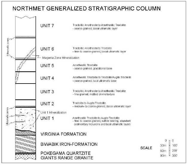
| 7.1.2 | Rock Type and Unit Classification |
Igneous rock types in the Complex are classified at NorthMet by visually estimating the modal percentages of plagioclase, olivine, and pyroxene. Due to subtle changes in the percentages of these minerals, a variation in the defined rock types within the rock units may be present from interval to interval or hole to hole. This is especially true for Unit 1.
Unit definitions are based on: overall texture of a rock type package; mineralogy; sulphide content; and context with respect to bounding surfaces (i.e., ultramafic horizons, oxide-rich horizons). Unit definitions are not always immediately clear in logging, but usually clarified when drill holes are plotted on cross-sections. In other words, to correctly identify a particular igneous stratigraphic unit, the context of the units directly above and below must
| Page | 7-4 | |
| 12/10/2012 |
| POLYMET MINING CORP. | |
| UPDATED TECHNICAL REPORT ON THE NORTHMET DEPOSIT | |
| MINNESOTA, USA |
also be considered. Figure 7-3 shows a plan view of the NorthMet geological contacts within the mining lease area.
| Page | 7-5 | |
| 12/10/2012 |
| POLYMET MINING CORP. | |
| UPDATED TECHNICAL REPORT ON THE NORTHMET DEPOSIT | |
| MINNESOTA, USA |
| Figure 7-3: | NorthMet Geological Contacts |

| Page | 7-6 | |
| 12/10/2012 |
| POLYMET MINING CORP. | |
| UPDATED TECHNICAL REPORT ON THE NORTHMET DEPOSIT | |
| MINNESOTA, USA |
Based on drill hole logging, the generalized rock type distribution at NorthMet is about 83% troctolitic, 6% anorthositic, 4% ultramafic, 4% sedimentary inclusions, 2% noritic and gabbroic rocks, and the rest as pegmatites, breccia, basalt inclusions and others
| 7.1.3 | Unit Definitions and Descriptions |
Unit 7
Unit 7 is the uppermost unit intersected in drill holes at the NorthMet Deposit. It consists predominantly of homogeneous, coarse-grained, anorthositic troctolite and troctolitic anorthosite. The unit is characterized by a continuous basal ultramafic sub-unit that averages 20 ft thick. The ultramafic consists of fine- to medium-grained melatroctolite to peridotite and minor dunite. The average thickness of Unit 7 is unknown due to the truncation by erosion on the surface exposure.
Unit 6
Very similar to Unit 7, Unit 6 is composed of homogeneous, fine- to coarse-grained, troctolitic anorthosite to troctolite. It averages 400 ft thick and has a continuous basal ultramafic sub-unit that averages 15 ft thick. Overall, sulphide mineralization is generally minimal, although a number of drillholes in the south-western portion of the NorthMet Deposit contain significant copper sulphides and associated elevated PGEs (Geerts 1991, 1994). Sulphides within Unit 6 generally occur as disseminated chalcopyrite/cubanite with minimal pyrrhotite. This mineralized occurrence (the Magenta Zone) is discussed in greater detail in the following sections.
Unit 5
Unit 5 exhibits an average thickness of 250 ft and is composed primarily of homogeneous, equigranular-textured, coarse-grained anorthositic troctolite. Anorthositic troctolite is the predominant rock type, but can locally grade into troctolite and augite troctolite towards the base of the unit. The lower contact of Unit 5 is gradational and lacks any ultramafic sub-unit; therefore the transition into Unit 4 is a somewhat arbitrary pick. Due to the ambiguity of this contact, thicknesses of both units vary dramatically. However, when Units 5 and 4 are combined, the thickness is fairly consistent deposit-wide.
Unit 4
Being somewhat more mafic than Unit 5, Unit 4 is characterized by homogeneous, coarse-grained, ophitic augite troctolite with some anorthosite troctolitic. Unit 4 averages about 250 ft thick. At its base, Unit 4 may contain a discontinuous, local, thin (usually no more than six inches) ultramafic layer or oxide-rich zone. The lower contact with Unit 3 is generally sharp. Overall, outside of the Magenta Zone, sulphides only occur in trace amounts within Unit 4 as finely disseminated grains of chalcopyrite and pyrrhotite.
| Page | 7-7 | |
| 12/10/2012 |
| POLYMET MINING CORP. | |
| UPDATED TECHNICAL REPORT ON THE NORTHMET DEPOSIT | |
| MINNESOTA, USA |
Unit 3
Unit 3 is used as the major “marker bed” in determining stratigraphic position in drill core. It is composed of fine- to medium-grained, poikilitic and/or ophitic, troctolitic anorthosite to anorthositic troctolite. Characteristic poikilitic olivine gives the rock an overall mottled appearance. On average, Unit 3 is 300 ft thick. The lower contact of Unit 3 can be disrupted, with multiple “false starts” into typical Unit 2 homogenous rocks, only to go back to mottled
Unit 3 with depth. The alternating sequence is common in the south western portion of the NorthMet Deposit and can span for many tens of ft along core before finally settling into definitive Unit 2. This most likely indicates that Unit 3 is broken up in this area and intruded by Unit 2 near the base of Unit 3. As with Units 4 and 5, the thickness of Units 2 and 3 tend to be highly variable, whereas if combined into one unit, it is more consistent deposit-wide (though not as consistent as Units 4 and 5).
Unit 3 can contain both footwall meta-sedimentary (Virginia Formation) and hanging wall basalt inclusions, which seems to indicate earliest emplacement within the intrusive sequence of the NorthMet Deposit. This exemplified by the fact that few sedimentary inclusions are found above Unit 3 and few basalt inclusions are found below it, as if Unit 3 was initially intruded between these units and eventually formed a barrier between them.
Unit 2
Unit 2 is characterized by homogeneous, medium- to coarse-grained troctolite and pyroxene troctolite with a consistent basal ultramafic sub-unit. The continuity of the basal ultramafic sub-unit, in addition to the relatively uniform grain size and homogeneity of the troctolite, makes this unit distinguishable from Units 1 and 3. Unit 2 has an average thickness of 100 ft. The ultramafic sub-unit at the base of Unit 2 is the lowermost continuous basal ultramafic horizon at the NorthMet Deposit, averages 25 ft thick, and is composed of melatroctolite to peridotite and minor dunite.
In some ways the characteristics of Unit 2 and how it fits into the igneous stratigraphy and the sequence of intrusion are ambiguous; it can be interpreted as the lower part of Unit 3, the upper part of Unit 1, or a separate unit. Based on continuity of the ultramafic boundary it seems to be a lower, more mafic, counterpart to Unit 3. The general lack of footwall inclusions in Unit 2 would argue against Unit 2 being older than Unit 1 and would indicate an intrusion sequence of 3, 1 then 2. Though Unit 2 has been historically described as barren, in the western part of the NorthMet Deposit it has mineralization grossly continuous with that at the top of Unit 1.
Unit 1
Of the seven igneous rock units represented within the NorthMet Deposit, Unit 1 is the only unit that contains significant deposit-wide sulphide mineralization. Sulphides occur primarily as disseminated interstitial grains between a dominant silicate framework and are
| Page | 7-8 | |
| 12/10/2012 |
| POLYMET MINING CORP. | |
| UPDATED TECHNICAL REPORT ON THE NORTHMET DEPOSIT | |
| MINNESOTA, USA |
chalcopyrite > pyrrhotite > cubanite > pentlandite. Unit 1 is also the most complex unit, with internal ultramafic sub-units, increasing and decreasing quantities of mineralization, complex textural relations and varying grain sizes, and abundant metasedimentary inclusions. It averages 450 ft thick, but is locally 1,000 ft thick and is characterized lithologically by fine- to coarse-grained heterogeneous rock ranging from anorthositic troctolite (more abundant in the upper half of Unit 1) to augite troctolite with lesser amounts of gabbro-norite and norite (becoming increasingly more abundant towards the basal contact) and numerous metasedimentary inclusions. By far the dominant rock type in Unit 1 is medium-grained ophitic augite troctolite, but the textures can vary wildly. Two internal ultramafic sub-units occur in drill holes in the southwest, and have an average thickness of 10 ft.
Footwall: Animikie Group and Archean Rocks
The footwall rocks of the NorthMet Deposit consist of Paleoproterozoic (meta) sedimentary rocks of the Animikie Group. These rocks are represented by the following three formations, listed from youngest to oldest: the Virginia Formation; the Biwabik Iron Formation; and the Pokegama Quartzite. They are generally underlain by Archean granite of the Giants Range Batholith, but there are Archean basalts and metasediments mapped in outcrop near the Project area. The Duluth Complex is only in contact with the Virginia Formation at the NorthMet site.
Intrusion of the Complex metamorphosed the Virginia. Non-metamorphosed Virginia Formation (as found to the north of the site) consists of a thinly-bedded sequence of argillite and Greywacke, with lesser amounts of siltstone, carbonaceous-sulphidic argillite/mudstone, cherty-limey layers, and possibly some tuffaceous material. However, in proximity to the Duluth Complex, the grade of metamorphism (and associated local deformation) progressively increases, and several metamorphic varieties and textures are superimposed on the original sedimentary package at an angle to the original stratigraphy. At least four distinctive Virginia Formation varieties are present at NorthMet and informally referred to as Cordieritic Metasediments; Disrupted Unit; Recrystallized Unit; and Graphitic Argillite (often with pyrrhotite laminae). These sub-units are fully described in Severson et al., 2000.
Inclusions in the Duluth Complex
Two broad populations of inclusions occur at NorthMet: hanging wall basalts (Keweenawan) and footwall meta-sedimentary rocks. Basalts are fine-grained, generally gabbroic, with no apparent relation to any mineralization. Footwall inclusions may carry substantial sulphide (pyrrhotite) and often appear to contribute to the local sulphur content. Footwall inclusions are all Virginia Formation, no iron-formation, Pokegama Quartzite, or older granitic rock has been recognized as an inclusion at NorthMet.
Sedimentary inclusions make up about 4% of the logged rock types, and basalt inclusions sum to less than 1% of the drilling footage.
| Page | 7-9 | |
| 12/10/2012 |
| POLYMET MINING CORP. | |
| UPDATED TECHNICAL REPORT ON THE NORTHMET DEPOSIT | |
| MINNESOTA, USA |
Generally, hanging wall inclusions are restricted to Unit 3 and the units above, while footwall inclusions are most abundant in Unit 1.
| 7.2 | Mineralization |
The metals of interest at NorthMet are copper, nickel, cobalt, platinum, palladium and gold. Minor amounts of rhodium and ruthenium are present though these are considered to have no economic significance. In general, with the exception of cobalt and gold, the metals are positively correlated with copper mineralization. Cobalt is well correlated with nickel.
Mineralization occurs in four broadly defined horizons or zones throughout the NorthMet property. Three of these horizons are within basal Unit 1, though they likely will not be discriminated in mining. The upper horizon locally extends upward into the base of Unit 2. The thickness of each of the three Unit 1 enriched horizons varies from 5 ft to more than 200 ft. Unit 1 mineralization is found throughout the base of the NorthMet Deposit. A less extensive (the copper-rich, sulphur-poor Magenta Zone) mineralized zone is found in Units 4, 5 and 6, in the western part of the NorthMet Deposit.
Mineralization occurs in two broad forms. Firstly, sulphides may be disseminated in heterogeneous troctolitic rocks (mainly Unit 1) in which the grain sizes of both silicates and sulphides widely vary. The occurrence and amount of this mineralization within drill holes can be unpredictable over the scale of 20 to 30 ft though mineralization is relatively constant in some horizons (i.e., top of Unit 1). Secondly, economic concentrations of sulphides in the upper units tend to be coarser grained and copper-rich (Units 2 to 7, particularly the Magenta Zone).
Sulphide mineralization consists of chalcopyrite and cubanite, pyrrhotite and pentlandite, with minor bornite, violarite, pyrite, sphalerite, galena, talnakhite, mackinawite and valerite. Sulphide minerals occur mainly as blebs interstitial to plagioclase, olivine and augite grains, but also may occur within plagioclase and augite grains, as intergrowths with silicates, or as fine veinlets. Small globular aggregates of sulphides (less than two centimetres) have been observed in core and in the small test pit on the site. The percentage of sulphide varies from trace to about 5%, but is rarely greater than 3%. Local massive sulphide is present, but rare. Platinum, palladium, and gold are associated with the sulphides as well as in tellurides and bismuthides.
| Page | 7-10 | |
| 12/10/2012 |
| POLYMET MINING CORP. | |
| UPDATED TECHNICAL REPORT ON THE NORTHMET DEPOSIT | |
| MINNESOTA, USA |
| 8 | DEPOSIT TYPES |
The NorthMet Deposit is a large-tonnage, disseminated accumulation of sulphide in mafic rocks, with rare massive sulphides. Copper to nickel ratios generally range from 3:1 to 4:1. Primary mineralization is probably magmatic, though the possibility of structurally controlled re-mobilization of the mineralization (especially PGEs) has not been excluded. Sulphur source is both local and magmatic (Theriault et al., 2000). Extensive detailed logging has shown no definitive relation between specific rock type and the quantity or grade quality of sulphide mineralization in the Unit 1 mineralized zone or in other units, though the localized noritic to gabbronoritic rocks (related to footwall assimilation) tend to be of poorer PGE grade and higher in sulphur.
Footwall faults are inferred from bedding dips in the underlying sedimentary rocks, considering the possibility that Keweenawan syn-rift normal faults may affect these underlying units and show less movement, or indeed no effect on the igneous units. Nonetheless, without faults, the footwall or igneous unit dips do not reconcile perfectly with the overall slope of the footwall. There are some apparent offsets in the igneous units, but definitive and continuous fault zones have not been identified. So far, no apparent local relation between the inferred location of faults and mineralization has been delineated.
Outcrop mapping (Severson and Zanko, 1996) shows apparent unit relations that require faults for perfect reconciliation. However, as with information derived from drill core, neither igneous stratigraphic unit recognition, nor outcrop density, is sufficiently definitive to establish exact fault locations without other evidence.
There is a wealth of regional (and some local) geophysical data available, though the resolution of core logging and field mapping is probably better than that of the geophysics, hence while the geophysical data is interesting, it has not yet been useful at delineating the structural geology of the site nor proved to be a guide to mineralization.
| Page | 8-1 | |
| 12/10/2012 |
| POLYMET MINING CORP. | |
| UPDATED TECHNICAL REPORT ON THE NORTHMET DEPOSIT | |
| MINNESOTA, USA |
| 9 | EXPLORATION |
Exploration history is outlined in Section 6. In general, the early drilling by US Steel is widely spaced but comparatively regularly distributed (approximately 600 ft by 600 ft), with some omissions that left substantial undrilled areas, especially down-dip. Subsequent programs by PolyMet were first focused on extracting metallurgical samples and on proving the up-dip and more readily accessible parts of the NorthMet Deposit. Besides extensive in-fill drilling since 2005, PolyMet has also expanded the definition of the mineralized zones to the west and southwest. In particular, it has become evident that the Magenta Zone, located in the upper units in the western part of the NorthMet Deposit, is much more robust than previously thought.
Those parts of the NorthMet Deposit at greater depth largely continue to have the original US Steel drill-hole spacing, which, in the eastern half of the NorthMet Deposit, is approximately 600 ft by 1,200 ft.
Drill spacing in the deepest known section of the NorthMet Deposit is approximately 1,200 ft by 1,200 ft. The Deposit is definitely open at depth and along strike. The deeper parts of the NorthMet Deposit (below about 1,600 ft from surface) may be of interest in the future, but they are considered to fall outside the scope of the current evaluation.
Drill hole spacing averages between 190 and 200 ft in the area of the resource model. This excludes holes drilled for metallurgical or geotechnical purposes. Distance studies show that 50% of the drillhole intercepts within Unit 1 will be within a 197 ft distance from another hole. In the Magenta Zone, 50% of the drillhole intercepts will be within a 190 ft distance from another hole. The best drilled area is in the vicinity of the preliminary optimum pit. This area also contains near-surface mineralization and is drilled at a spacing of about 150 ft (excluding geotechnical and metallurgical holes) from 171 holes.
| Page | 9-1 | |
| 12/10/2012 |
| POLYMET MINING CORP. | |
| UPDATED TECHNICAL REPORT ON THE NORTHMET DEPOSIT | |
| MINNESOTA, USA |
| 10 | DRILLING |
There have been four major (and one minor) drilling campaigns on the property as shown in Figure 10-1. This discussion is largely taken from Patelke and Geerts (2006).
In all cases, drilling has shown a basal mineralized zone (Unit 1) in heterogeneous troctolitic rocks with the highest values at its top and with grades generally diminishing with vertical depth along drill holes. Grade appears to increase down dip, but as depth increases less information is available. The main ore zone is from 200 to 1,000 ft thick, averaging about 450 ft. Mineralization sub-crops at the north edge of the NorthMet Deposit and continues to depths of greater than 2,500 ft. Sampling on the longest holes is sparse, with little in-fill work done since the original US Steel sampling (PolyMet took about 700 samples from these longer holes in spring of 2006, these data are included in the drilling database)
While the concept of some structural control on mineralization is valid (i.e., proximity to a vent system or re-mobilization of some metals) no evidence collected to date fully supports this view. More likely, this is a magmatic sulphide system which was then contaminated by sulphur from locally assimilated footwall rocks and modified to some extent by (late magmatic?) hydrothermal action.
Core recovery (Table 10-1) is reported by PolyMet to be upwards of 99% with rare zones of poor recovery. Rock quality designation (RQD) is also very high, upward of 85% for all units except in the Iron formation. Experience in the Duluth Complex indicates that core drilling has no difficulty in producing samples that are representative of the rock mass. Rock is fresh and competent and the common types of alteration (sausserization, uralization, serpentinization and chloritization) in the NorthMet Deposit are not those that affect recovery. Core recovery was recorded by US Steel and PolyMet in its earlier work and for the smaller diameter (NQ2 and NTW) drilling in since 2005. There is no readily apparent relation of recovery to sulphur content or rock type. Values in excess of 100 may arise from errors associated with assembling broken core or from core runs that are slightly longer than the core barrel. AGP comment that the core recovery appears very good in the holes that were inspected during the site visits.
In short-range detail, the NorthMet Deposit geology is subtle and complex. However, mineralogical and textural variation occurs within narrow ranges and at the mining scale, the overriding lithology will be troctolite to augite-troctolite (plagioclase>olivine>>pyroxene with biotite and minor ilmenite). The known ultramafic horizons are thin enough, and metasedimentary inclusions small enough, that material handling will homogenize the plant feed, as accounted for in the bulk samples. In general, rocks are medium- to coarse-grained, fresh, and competent.
| Page | 10-1 | |
| 12/10/2012 |
| POLYMET MINING CORP. | |
| UPDATED TECHNICAL REPORT ON THE NORTHMET DEPOSIT | |
| MINNESOTA, USA |
| Figure 10-1: | Drillhole Collar Location by Campaign |
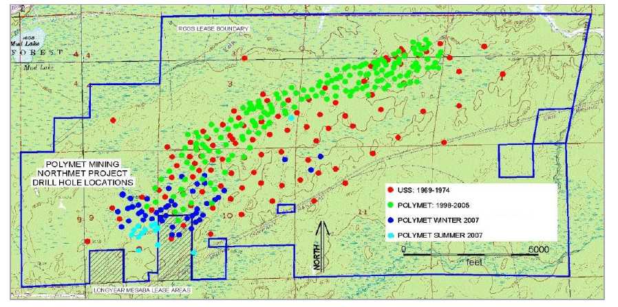
| Page | 10-2 | |
| 12/10/2012 |
| POLYMET MINING CORP. | |
| UPDATED TECHNICAL REPORT ON THE NORTHMET DEPOSIT | |
| MINNESOTA, USA |
| Table 10-1: | Summary of Core Recoveries and RQD Measurements | |
| (includes all drilling through summer 2007) |
Unit | Recovery Count | Recovery Percentage (%) | RQD Count | RQD Percent |
| 1 | 8,906 | 99.9 | 4,194 | 91.8 |
| 2 | 1,879 | 99.5 | 968 | 90.3 |
| 3 | 4,374 | 100 | 2,632 | 93.5 |
| 4 | 2,160 | 100 | 1,063 | 96.4 |
| 5 | 1,901 | 100 | 838 | 94.3 |
| 6 | 2,262 | 100 | 1,041 | 94.7 |
| 7 | 951 | 99.3 | 396 | 87.4 |
| Virginia Formation | 2,095 | 99.7 | 1,069 | 87.6 |
| Inclusions | 62 | 98.1 | 57 | 86.6 |
| Biwabik Iron Formation | 381 | 100 | 60 | 79.8 |
| Duluth Complex Average | 99.96 | 92.82 |
| 10.1 | Drilling Campaign |
| 10.1.1 | US Steel Drilling, 1969-1974 |
From 1969 to 1974, US Steel drilled 112 holes across the property. Drilling began in an attempt to intersect a geophysical conductor (virtually all of the deposits in the area were originally drilled on geophysical targets) and the first hole hit three ft of massive sulphide with 4.8% copper, 115 ft from the surface. Drilling continued, without discovery of any more such dramatic results and eventually defined a broad zone of low-grade copper-nickel sulphide mineralization. Further drilling indicated that the original geophysical target was graphitic argillite in the footwall, rather than any mineralization in the Duluth Complex.
US Steel assayed only about 22,000 ft of the 133,000 ft they drilled, generally on 10 ft intervals. Their focus was on developing an underground reserve and sampling was limited to zones of continuous “higher grade” mineralization. As in many exploration projects, sampling focused on the expected main ore body, not more scattered intervals or assumed waste rock. US Steel was aware of the PGE value from the assaying of concentrates derived from bench work and test pits, but did no assaying for these metals on drill core. Nearly all core was BQ size, and only 14 of the holes were angled (all to the northwest, grid north). Hole depths ranged from 162 ft to 2,647 ft, averaging 1,193 ft. Five holes were over 2,500 ft in length.
US Steel drilling was by Longyear. Virtually all of the core from this program exists, is properly stored, and is available for further sampling. Seventeen US Steel holes were “skeletonised” after assaying, with only a ft kept for each five or ten ft “un-mineralized” and
| Page | 10-3 | |
| 12/10/2012 |
| POLYMET MINING CORP. | |
| UPDATED TECHNICAL REPORT ON THE NORTHMET DEPOSIT | |
| MINNESOTA, USA |
unsampled run. Core was split by US Steel using a manual core splitter. Samples submitted for assay were half core. US Steel assays were done at their own laboratories; most of these have since been re-assayed by ACME Laboratories (ACME) or ALS Chemex (Chemex). Drilling by PolyMet near some of the locations of skeletonised holes has indicated the possibility that some mineralized intervals may have been missed and disposed of in the skeletonising process.
The US Steel geologists logged all their holes, but neither recognized nor documented any comprehensive igneous stratigraphy. Mark Severson of the Natural Resources Research Institute (NRRI), Duluth, Minnesota began re-logging these holes in the late 1980’s as part of a Partridge River intrusion geochemistry project. He quickly recognized Unit 3 as a marker horizon, which led to reliable correlations among the other units.
Steve Geerts, working for the NRRI with Fleck Resources (PolyMet precursor), refined the geologic model for the NorthMet Deposit in light of this igneous stratigraphy. This basic model is still considered by PolyMet to be valid and currently guides the interpretation of the NorthMet Deposit (Severson 1988, Severson and Hauck 1990, Geerts et al. 1990, Geerts 1991, 1994).
| 10.1.2 | NERCO Drilling, 1991 |
NERCO conducted a minor drilling campaign in 1991—four holes at two sites. At each site a BQ sized core hole (1.43 inches) was drilled and sampled from collar to bottom of hole. A PQ (3.3 inch) hole twinned each of these two holes and was sent in its entirety for metallurgical work on the assumption that the assays on the smaller diameter core would represent the larger diameter core. Both sets of holes twinned existing US Steel holes (Pancoast, 1991).
One-hundred and sixty-five assays were taken from the smaller diameter cores and processed at ACME.
| 10.1.3 | PolyMet Drilling, 1998-2000, Reverse Circulation Holes |
PolyMet drilled 52 vertical reverse circulation (RC) holes to supply material for a bulk sample in 1998 to 2000. These holes twinned some US Steel holes and others served as in-fill for parts of the NorthMet Deposit. The drilling was done by a contractor from Duluth with extensive RC experience and was carried out in both summer and winter. The type of bit and extraction system used (cross-over sub or face-sampling) is not known. Available recorded sample weights indicate a recovery of at least 85%. Metallurgical core drilling in February and March 2005 approximately twinned some of these RC holes.
The PolyMet drilling in 1998 to 2000 targeted the up-dip portions of the NorthMet Deposit and was essentially in-fill drilling. Reverse circulation holes averaged 474 ft in length with a minimum of 65 ft and a maximum depth of 745 ft. Core holes averaged 692 ft in length with
| Page | 10-4 | |
| 12/10/2012 |
| POLYMET MINING CORP. | |
| UPDATED TECHNICAL REPORT ON THE NORTHMET DEPOSIT | |
| MINNESOTA, USA |
a minimum of 229 ft and a maximum depth of 1,192 ft (this does not include the three RC holes completed with AQ core).
The RC holes were assayed on five ft intervals. Six inch reverse circulation drilling produced about 135 lb to 150 lb of sample for every five ft of drilling. This material was split using a riffle splitter into two samples and placed in plastic bags and stored underwater in five gallon plastic buckets. A 1/16th sample was taken by rotary splitter from each five ft of chip sample and assayed. The assay values were used to develop a composite pilot plant sample from bucket samples. Actual compositing was done after samples had been shipped to Lakefield (Patelke and Severson, 2006). A second 1/16th sample was sent to the Minnesota Department of Natural Resources for their archive.
Chip samples were collected and later logged at the PolyMet office. PolyMet retains these samples in their warehouse. Logging is obviously not as precise as that for core, but the major silicate and sulfide minerals can be recognized and location of marker horizons derived. The underlying metasedimentary rocks (Virginia Formation) are easily recognized and finding the bottom of the NorthMet Deposit is relatively straightforward. Where rock recognition is difficult, the higher zinc content of the footwall rocks can help define the contact.
| 10.1.4 | PolyMet Drilling, 1999 to 2000, Diamond Core Holes |
The first PolyMet core-drilling program was carried out during the later parts of the RC program, with three holes drilled late in 1999 and the remainder in early 2000. There were seventeen BTW (1.65 inch) and fifteen NTW (2.2 inch) holes all of which were vertical. Three RC holes were re-entered and deepened with AQ core.
These holes were assayed from top to bottom (with rare exception) on five ft lengths. Samples were half core. Cutting was done at the PolyMet field office in Aurora, Minnesota.
Core logging was done at the PolyMet office by a variety of geologists, all trained in recognition of the units and the subtleties of the mineralogy and textures by Mark Severson of the NRRI.
| 10.1.5 | PolyMet Drilling, 2005, Diamond Core Holes |
PolyMet’s 2005 drilling program had four distinct goals: collection of metallurgical sample; continued in-fill drilling for resource estimation; drilling outward from the margins of the well drilled area to expand resource; and collection of geotechnical data through core logging and recovery of oriented cores. The program covered 109 holes for 77,165 ft. These included:
54 one inch diameter holes for metallurgical sample (6,974 ft) drilled by Boart- Longyear of Salt Lake City in February-March 2005.
| Page | 10-5 | |
| 12/10/2012 |
| POLYMET MINING CORP. | |
| UPDATED TECHNICAL REPORT ON THE NORTHMET DEPOSIT | |
| MINNESOTA, USA |
12 PQ sized holes (core diameter 3.3 inches) for 6,897 ft, mostly used for bulk sample material, but with a few holes intended as in-fill. The PQ holes were also all drilled in February-March of 2005.
52 NTW sized holes (2.2 inches) totalling 41,403 ft for resource definition.
30 NQ2 sized holes (2.0 inches) totalling 21,892 ft for resource definition and geotechnical purposes. The NTW and NQ2 size core was drilled in February-March and September-December of 2005.
About 11,650 multi-element assays were collected from the 2005 drilling program. Another 1,790 assays were performed on previously drilled US Steel and PolyMet core during that time. All assaying was by ALS-Chemex.
Of the 109 holes drilled in 2005, 93 were angled, generally to grid north at dips of -60°to -75°. Sixteen NQ2 sized holes were drilled and marked as oriented core, ten to grid south and six to grid north, at varying dips, for geotechnical assessment across the NorthMet Deposit. These holes targeted expected positions of pit walls as defined by Whittle pit shells developed by mining consultants AMDAD and available in January 2005. These locations have proved to be reasonable for more recent iterations of pit design.
Besides extensive assaying for “pay” elements during this program, about 900 core intervals were analyzed for “whole rock” oxides, about 300 samples were analyzed for Rare Earth
Elements (REE), and thousands of density measurements were taken. This data is used to support resource evaluation as well as waste characterization efforts for permitting.
Separately, about 100 samples from previously drilled and analyzed core were submitted for humidity cell testing. These samples represented a broad cross-section of Units, rock-types, metals content, and sulphur content. In addition, these humidity cell samples were all re-assayed, analyzed for whole rock and assessed in thin-section and by micro-probe.
| 10.1.6 | PolyMet Drilling, 2007, Diamond Core Holes |
In 2007, PolyMet conducted two drilling programs, a winter program for 47 holes over 19,102.5 ft and a summer program for 14 holes over 5,437.5 ft. The first 16 winter holes were NTW sized, the rest from both programs were NQ2 sized core. Most of these holes were angled to north-northeast (azimuth 326°).
For the 2007 holes the minimum length was 148 ft, the maximum length was 768.5 ft and the average length was 402 ft.
During the site visit, AGP noted that the drill core handling procedure carried out by Polymet met or exceed industry standard. Drill hole orientation and dip results in intersection with the lithological units that are more or less normal to the main structural trend and are appropriate for the style of mineralization present on the NorthMet Deposit.
| Page | 10-6 | |
| 12/10/2012 |
| POLYMET MINING CORP. | |
| UPDATED TECHNICAL REPORT ON THE NORTHMET DEPOSIT | |
| MINNESOTA, USA |
| 11 | SAMPLE PREPARATION, ANALYSES, AND SECURITY |
Sections 11.1 and 11.2 were extracted from the Hellman 2005 report.
| 11.1 | Sampling Methods |
Original US Steel sampling, generally on 10 ft intervals, honoured some, but not all, of the geological boundaries that were encountered. The PolyMet RC sampling transgressed boundaries, though the five ft chip samples diminish the opportunity for this to be of any consequence in a bulk mining (15 to 20 ft bench or greater) scenario.
Sampling of US Steel core by Geerts, Severson, and Patelke of NRRI at various times usually was on five ft samples and seldom crossed any significant geologic boundaries. Core sampling by PolyMet in 1999 and 2000 was usually on five ft intervals and crossed unit boundaries, as with the RC samples, the short sample length negates any major effect from this sampling choice. Sampling by PolyMet on the US Steel core in 2005 was generally on 10 ft intervals, but did not cross any major geologic boundaries and included some shorter intervals. Sampling of in-fill (NTW and NQ2) core in 2005 and 2007 used five ft samples in the main mineralized zone and 10 ft in the upper zones. This was adjusted to use smaller intervals in the upper parts with visible mineralization and did not cross-geologic boundaries.
Large diameter core collected for metallurgical sample was sampled and assayed by the box with the goal of minimizing re-handling during the preparation and compositing of the bulk sample. Four-inch core was sampled on an average interval of 3.45 ft, and PQ core was sampled on an average interval of 4.47 ft.
Table 11-1 shows average length of samples in Unit 1 and all other units for holes used in the resource model. Approximately 90.5% of Unit 1 and about 55.5% of the other units have been sampled project-wide. About 70% of the total exploration drilling by US Steel and PolyMet has been sampled across the property. Over 97% of the drilling intercepting the anticipated 20-year pit has been sampled.
| Table 11-1: | Sample Lengths (includes all drilling through summer 2007) |
| Average Sample Length in Unit 1 (ft) | Average Sample Length in Other Units (ft) | |
| US Steel Original Core | 6.3 | 7.1 |
| PolyMet RC Drilling | 5.0 | 5.0 |
| PolyMet Core Drilling | 4.8 | 7.2 |
| All Drilling | 5.3 | 7.0 |
| Page | 11-7 | |
| 12/10/2012 |
| POLYMET MINING CORP. | |
| UPDATED TECHNICAL REPORT ON THE NORTHMET DEPOSIT | |
| MINNESOTA, USA |
Sampling in Unit 1 (the main mineralized zone) is mostly continuous through the zone for all generations of drilling. The older PolyMet RC and core holes have continuous sample through the upper waste zones (which do have some intercepts of economic mineralization). Work in 2005 and 2006 essentially completed the sampling of historic US Steel core within the area likely to be mined. This broad sampling limits the possibility of bias in the sample set. The 2005 and 2007 sampling has been continuous along the drill hole. There is some US Steel core below the current block model to be sampled in the future. The overall effect on the resource should be minimal and is expected to be positive.
| 11.2 | Preparation and Analysis |
| 11.2.1 | Sample Preparation Pre-2000 |
Bright (2000), an employee of ALS Chemex, summarized the sample preparation history of the Project up to that point, the following is an extract from his summary.
Pre-1996, Lerch Brothers, and State of Minnesota crushed in a jaw crusher to about 1/4 inch and pulverized about 250g in a Bico type plate pulverizer to about -100 mesh (149 µm). Bondar Clegg also did some work on the Project, crushing about the same, but pulverizing in a ring mill to -106 µm.
In 1997, samples were sent directly to Acme Laboratories, where they crushed to finer than 1/4 inch and pulverized to about 149 to 106 µm range.
In 1998, Lerch Bros. crushed and pulverized about 250 g in an older ring mill to finer than 149 µm and sent to Acme.
In 1999, Lerch Bros. prepped as in 1998, but sent to Chemex for analysis. Early on in the Project, I requested a finer grind out of Lerch Bros, and they accomplished it. (-106 mic). Also in 1999, some drill cuttings and core were directly picked up by ALS Chemex. This is what we did in Thunder Bay:
3.5-4 kg of RC or percussion samples were dried and split to obtain two splits of each sample. Core samples of 2.5 to 3 kg were crushed to pass >70% -2 mm, 200 to 300 g were split out. Both r.c. cuttings and crushed core were shipped to Toronto for pulverizing in a ring mill to >95% -106 µm (-150 Tyler mesh).
We also took selected core samples and crushed to -1/2 inch and put in a poly bottle, purged with nitrogen, and capped and sealed for special met / enviro work.
| 11.2.2 | Sample Preparation Pre-2005 |
In summary (Gatehouse 2000a), pre-2005 drilling has been prepared in either of two ways depending on drill type or on the work load of Lerch Bros in Hibbing.
5’ of 6” RC chips
| Page | 11-8 | |
| 12/10/2012 |
| POLYMET MINING CORP. | |
| UPDATED TECHNICAL REPORT ON THE NORTHMET DEPOSIT | |
| MINNESOTA, USA |
1/16 split using an Eklund rotary Splitter (3 to 4 kg)
Jaw crush >> Gyratory Crusher >> Rolls crusher
1/16 split to 200 to 250 g for pulverizing to 109 µm (some data poorly pulped to 150 µm)
5’ of 1/2 core (1.65” and 2.2”diameter, BTW, NTW) at Chemex
Rhino (Jaw) Crush to 2 mm
Split 200 to 250 g for pulverizing to 109 µm
5’ of 1/2 core (1.65” & 2.2”diameter, BTW, NTW) at Lerch Bros.
Jaw Crush >> Gyratory Crusher
Split 200 to 250 g for pulverizing to 149 µm.
| 11.2.3 | Sample Preparation 2005 through 2007 |
The 2005 and 2007 sample preparation varied at the cutting and sampling stage with ½ core samples used for all NQ2 and NTW drilling and 1/8 core samples used for all four inch and PQ drilling. For smaller diameter core, the field duplicates were ¼ core, for the larger cores the field duplicates were 1/8 core.
All sample preparation after cutting was done at ALS Chemex in Thunder Bay, Ontario, and all analyses at ALS-Chemex in Vancouver, B.C. Transport from Hoyt Lakes to Thunder Bay was by truck driven by ALS-Chemex employees and under ALS-Chemex custody.
Sample preparation methods were as follows:
A 10 lb to 15 lb sample was crushed in a single stage crusher to 90% -2 mm
A 500 to 700 g sample was split off and pulverized to -150 mesh in one pass
1 in 20 samples also duplicated at the crusher
Approximately 200 g for each sample were sent to Vancouver
All samples were analyzed for multi-element ICP package (four acid digestion) and PGE
Depending on batch size and other factors 1 in 10 to 1 in 20 samples were submitted as pulps for analysis for whole rock major elements, aqua regia digestion, REE and iron oxide (FeO)
A standard, coarse blank (iron formation) or core (field) duplicate was submitted at a rate of one in every 12 samples
LECO Corporation (LECO) furnace sulphur was run on 1 in 10 samples.
| Page | 11-9 | |
| 12/10/2012 |
| POLYMET MINING CORP. | |
| UPDATED TECHNICAL REPORT ON THE NORTHMET DEPOSIT | |
| MINNESOTA, USA |
| 11.3 | Analytical History |
The following discussion is derived largely from Patelke and Geerts (2006), an internal company report on the compilation and history of the newly revised PolyMet drilling database.
There are eight generations of sample preparation and analyses that contribute to the overall project assay database:
Original US Steel core sampling, by US Steel, 1969-1974 | ||
Re-assaying of US Steel pulps and rejects, selection by Fleck and NRRI, 1989-1991 | ||
Sampling of previously unsampled US Steel core, sample selection by Fleck and NRRI in 1989-1991 | ||
Sampling of two NERCO drill holes in 1991 | ||
Sampling of RC cuttings by PolyMet in 1998-2000 | ||
Sampling of PolyMet core in 2000 | ||
Sampling of previously unsampled US Steel core (sample selection work done by NRRI, done in two phases) in 1999-2001 | ||
|
| |
1. | Sampling of PolyMet core from 2005 drilling, continued sampling of previously unsampled US Steel core in 2005-2006, and sampling from 2007 drilling, with continued protocols in place since 2005. | |
2. | Employees of PolyMet (or Fleck Resources) have been either directly or indirectly involved in all sample selection since the original US Steel sampling. Sample cutting and preparation of core for shipping has been done by PolyMet employees or contract employees. Reverse circulation sampling at the rig was done by, or in cooperation with, PolyMet employees and drilling contractor employees. | |
3. | US Steel took about 2,200 samples, mostly ten ft in length, and assayed for copper, nickel, sulphur, and iron. Assays were done at two US Steel laboratories in Minnesota, the Applied Research Laboratory (ARL) in Coleraine (now the NRRI mineral processing laboratory), and the Minnesota Ore Operations Laboratory (MOO) at the MinnTac Mine in Mountain Iron. Most of the original US Steel samples have been superseded by ACME and Chemex re-assays which included many more elements. | |
4. | Analytical method at these US Steel laboratories is uncertain (AAS?). While standards were developed and used (as evidenced by documents in PolyMet files), it is not thought the standards were inserted into the sample stream in a blind manner. It is likely that these were used for calibration or spot checks. |
Page | 11-10 | |
| 12/10/2012 |
| POLYMET MINING CORP. | |
| UPDATED TECHNICAL REPORT ON THE NORTHMET DEPOSIT | |
| MINNESOTA, USA |
| 5. | There are less than 200 sets of US Steel copper-nickel values that remain in the database. | |
| 6. | PolyMet used 63 coarse reject US Steel samples, weighing from five to seven pounds each, to create three standards in 2004. The 2004 assay results are consistent with estimates based on original US Steel assays of drill core. The ALS-Chemex results are shown in Table 11-2. |
| Table 11-2: | ALS-Chemex Assays compared with US Steel Assays |
| Cu % | Ni % | S % | |
| Standard 1 expected value based on 1969 to 1974 US Steel assays | 0.18 | 0.08 | 1.04 |
| Standard 1 assayed value-2004 – Chemex | 0.20 | 0.11 | 1.08 |
| Standard 2 expected value based on 1969 to 1974 US Steel assays | 0.36 | 0.14 | 0.88 |
| Standard 2 assayed value-2004 – Chemex | 0.37 | 0.15 | 0.82 |
| Standard 3 expected value based on 1969 to 1974 US Steel assays | 0.55 | 0.18 | 1.17 |
| Standard 3 assayed value-2004 – Chemex | 0.57 | 0.21 | 1.04 |
Averages are based on twenty samples of each standard with 4-acid assays completed in 2004. In all cases, the US Steel results are slightly understated relative to the Chemex values. These standards have been used throughout the 2005 and 2007 programs.
The re-assaying of US Steel pulps and sampling of previously unsampled core completed in 1989-1991 was sponsored by Fleck Resources and partially involved cooperative work with the NRRI in Duluth. A large number of pulps and coarse reject from the original US Steel drilling were re-assayed for copper, nickel, PGE, and a full suite of other elements. The NRRI’s contribution was the selection and sampling (and re-logging) of previously unsampled core. This was the first large scale testing for PGE done on the Project.
About 2,600 of these analyses are in the current PolyMet database. All of this analytical work was done at ACME Laboratories by aqua regia with ICP-ES for copper and nickel. Gold, platinum, palladium were by lead-oxide (PbO) collection fire assay/AAS finish. There is uncertainty about the level of standards used at ACME, though it is certain that they used some duplicates. There is agreement between the ACME assays done on pulps and rejects and the original US Steel work. PolyMet is using the US Steel sulphur value for most of these intervals. Sample preparation for all this work is thought to have been done by ACME.
The two NERCO BQ core holes (1991, 162 samples) were analyzed at ACME by the same methods.
There are 5,216 analyses from the RC drilling in the current PolyMet database. The 1998 RC drilling program started with all analyses being sent to ACME and check assays going to
| Page | 11-11 | |
| 12/10/2012 |
| POLYMET MINING CORP. | |
| UPDATED TECHNICAL REPORT ON THE NORTHMET DEPOSIT | |
| MINNESOTA, USA |
Chemex. RC sample collection involved a 1/16 sample representing each five ft run. These were sent to Lerch Brothers of Hibbing Minnesota (Lerch), for preparation, and then sent to ACME for analysis. It is not certain that all samples were prepared at Lerch.
Part of the way through the RC program, PolyMet switched laboratories and sent the samples to Chemex, with ACME undertaking check assays. Analytical methods for the RC samples were aqua regia digestion, fire assay for PGE, and ICP-AES for other elements. LECO furnace sulphur was run on nearly every sample.
Table 11-3 details the distribution and source of the assays for the RC drilling.
| Table 11-3: | Assaying of RC Samples |
| Percent of Samples in Database | |
| ACME | 21 |
| Chemex | 41 |
| Chemex Re-run (chosen over ACME or Chemex) | 38 |
The PolyMet core drilling has all been assayed by ALS Chemex. A matrix problem was discovered on some copper and nickel assays in the earlier groups in 2000. The problem was rectified and affected samples were re-assayed (eventually including some RC samples). Sample preparation was done at Chemex, though some may have been done at the Lerch facility — various original Chemex laboratory certificates show both “received as pulp” and give grind directions. ACME ran the check assays on these samples.
Some samples on US Steel in 2000 core were done through ACME.
On pre-2005, post US Steel sampling, intervals were generally five ft, sometimes adjusted for geological breaks. Analyses were aqua regia digestion with fire assay for PGE and ICP-AES for other elements. LECO furnace sulphur was run on most intervals. During this program standards and blanks were inserted into the sample stream.
Table 11-4 details the distribution and source of assays for PolyMet core drilling.
| Table 11-4: | Assaying of Samples from all Core Drilling on Project |
| Percent of Samples in Database | |
| ACME | 6% |
| Chemex | 91% |
| Chemex Re-run | 3% |
| USS | < 1% |
| Page | 11-12 | |
| 12/10/2012 |
| POLYMET MINING CORP. | |
| UPDATED TECHNICAL REPORT ON THE NORTHMET DEPOSIT | |
| MINNESOTA, USA |
Samples (collected by Severson et al., in 1999-2000 and Patelke, in 2000-2001) of previously unsampled US Steel core were assayed by ALS Chemex. These samples were sawn at the Coleraine laboratory by University of Minnesota employees. At various times samples were prepared at the Coleraine laboratory, Lerch, and probably by ALS Chemex.
Assays were by aqua regia digestion with fire assay for PGE and ICP-AES for other elements. LECO furnace sulphur was run on most intervals. During this program, standards and blanks were inserted into the sample stream.
Samples were generally five ft in length, with some adjustments to avoid crossing geologic boundaries. This work was intended to supplement and in-fill the database, primarily in the Unit 1 mineralized zone as well as to provide some geochemical data for waste characterization.
The 2005 drilling and 2005-2006 sampling used four acid digestions on all samples, with aqua regia also done on about 1 in 10 samples. Since 2005, all samples have honored geological contacts.
PolyMet continued in 2005 and 2006 the process of assaying previously un-sampled US Steel core, adding about 1,700 assays during 2005-2006. The majority of this is in the anticipated 20 year pit.
Table 11-5 shows previously un-sampled intervals of US Steel core that were sampled by Severson et al (1999-2000) and Patelke (2000-2001).
No sieve tests are available for pre 2005 work. These were performed for samples from the 2005 and 2007 drilling programs.
| Table 11-5: | Details of Sampling of US Steel Core by PolyMet |
| Number of Samples in Database from each Laboratory | Minimum Number of Duplicates and/or Re-runs | |
| Chemex (Post Re-run) | 5,032 | 229 |
| 11.4 | Quality Assurance and Quality Control |
A comprehensive QA/QC program involving the use of coarse blanks, standards and duplicates has been instigated under the direction of Hellman and Schofield and Lynda Bloom of ASL, Toronto. This process consisted of the production of three matrix-matched standards from the Duluth complex, sample preparation and homogenization, homogeneity testing, formulation of recommended values based on a round robin and routine insertion of standards on an anonymous basis. The three standards have copper concentrations in the approximate range 0.15 to 0.60% and nickel from 0.1 to 0.2%. Homogeneity of pulps, as
| Page | 11-13 | |
| 12/10/2012 |
| POLYMET MINING CORP. | |
| UPDATED TECHNICAL REPORT ON THE NORTHMET DEPOSIT | |
| MINNESOTA, USA |
determined by coefficients of variation from 20 replicate assays, is excellent with, for example, values less than 2% for copper and nickel and less than 5% for palladium. Analytical method for the matrix match standard was ALS Chemex code ME-ICP61, 4 acid digestion ICP with AES finish for Co, Cu, Mo, Ni and Zn. For the platinum group metals and gold, ALS Chemex code PGM-ICP23, which is a 30 g fire assay with ICP-AES finish. Total sulphur was done by LECO furnaise Code S-IR08. Table 11-6 shows the expected value of the standards.
| Table 11-6: | Standard Reference Material |
Element | Standard 4-1 | Standard 4-2 | Standard 4-3 | |||
| Average | Std.Dev | Average | Std.Dev | Average | Std.Dev | |
| Co (ppm) | 90.1 | 10.44 | 95.10 | 10.64 | 110.73 | 11.11 |
| Cu (%) | 0.201 | 0.008 | 0.378 | 0.009 | 0.589 | 0.019 |
| Mo (ppm) | 13.87 | 1.78 | 9.61 | 1.36 | 12.25 | 1.40 |
| Ni (%) | 0.109 | 0.007 | 0.143 | 0.009 | 0.197 | 0.015 |
| Zn (ppm) | 174.15 | 14.62 | 116.77 | 12.18 | 124.76 | 12.65 |
| Au (ppb) | 57.85 | 12.70 | 33.32 | 6.48 | 54.18 | 7.36 |
| Pt (ppb) | 36.54 | 9.50 | 55.76 | 11.15 | 125.52 | 15.55 |
| Pd (ppb) | 117.52 | 10.66 | 238.95 | 14.64 | 518.05 | 22.18 |
| S (%) | 1.17 | 0.04 | 0.91 | 0.04 | 1.15 | 0.005 |
Reference materials (RMs) and Blanks were inserted at a rate of one blank with every 35 samples and 1 SRM with every 36 samples. Duplicate are submitted with every 36 samples. Typically, there are very few assay failures found in the drill programs with Chemex and they are investigated in batches by PolyMet. Depending on the nature of the failures, samples may be re-run or discarded from the data set. | |
| 11.4.1 | Linda Bloom Assessment of the QA/QC Program to 2005 |
AGP observes that Lynda Bloom of Analytical Solutions Ltd is independent from the issuer and specialized in sampling and analytical procedures, QA/QC program design, QC review and laboratory audits. She is very well known in her field and review the PolyMet 2005 quality control program. AGP reviewed the report provided to PolyMet from Lynda Bloom and agree with its findings. | |
| 11.4.2 | AGP Assessment of the QA/QC Program to 2007 |
AGP reviewed the data provided by PolyMet for the two main pay elements. Out of 526 RMs submitted between April 2005 through to June 2007, there was 54 copper failures (10.2%) most of which occur with RM 4-2 showing a 21.2 % failure rate. The other two RMs 4-1 and |
| Page | 11-14 | |
| 12/10/2012 |
| POLYMET MINING CORP. | |
| UPDATED TECHNICAL REPORT ON THE NORTHMET DEPOSIT | |
| MINNESOTA, USA |
4-3 indicated a failure rate of 2.9% and 5.0%, respectively. All copper standards showed increase deviation from the expected values for samples submitted after April 30, 2007.
For Nickel, out of 526 RMs submitted during April 2005 through to June 2007, there were six nickel failures (1.14%).
The exact number of batches resubmitted to the laboratory is unknown by the author.
| 11.5 | Databases |
It is AGP's opinion that PolyMet staff has made a strong commitment to the geological and assay database and have, as far as is possible, produced a database that is complete, well documented and traceable. | |
| 11.6 | Core Storage and Sample Security |
The US Steel core has been stored, either at the original US Steel warehouse in Virginia, Minnesota during drilling, or more recently at the Coleraine Minerals Research Laboratory (now a part of the University of Minnesota). Core has been secured in locked buildings within a fenced area that is locked at night where a key must be checked out. The NERCO BQ size core is also stored at this facility. | |
The PolyMet core and RC reference samples were stored in a PolyMet leased warehouse in Aurora, Minnesota during drilling and pre-feasibility. Core and samples were then moved in 2002 to a warehouse in Mountain Iron, Minnesota where they remained until 2004. They were then moved to a warehouse at the Erie Plant site in Hoyt Lakes. Access to this warehouse has been limited to PolyMet employees. | |
| 11.7 | Comments on Section 11 |
AGP is of the opinion that PolyMet went to considerable effort to ensure that the laboratory procedures, QA/QC protocol, the use of a matrix match standards and the continuous sampling of most of the historical holes. There was a weak degradation of precision at the laboratory starting April 30, 2007 to the end of the drill program. This is noticeable in both copper and nickel assays. The degradation was not sufficient to create a material change that would affect the resource model grade. | |
The distribution of the core drilling versus RC in the database (Table 11-7) shows that 91% of the holes used in the resources are core holes. RC holes amount only to 9% of the database. The reproducibility of the grade between RC and Core holes was investigated and found to be within acceptable limit. A discussion on that subject has been inserted in Section 12 of this report. |
| Page | 11-15 | |
| 12/10/2012 |
| POLYMET MINING CORP. | |
| UPDATED TECHNICAL REPORT ON THE NORTHMET DEPOSIT | |
| MINNESOTA, USA |
| Table 11-7: | Distribution of Drillhole Types |
| CORE_RC | No. of Holes | Length of Hole | Percent of Total |
| CORE | 299 | 227,665.50 | 80 |
| CORE-SKEL (partial assays) | 17 | 30,745.00 | 11 |
| RC | 52 | 24,650.00 | 9 |
| RC-CORE | 3 | 2,696.50 | 1 |
| 285,757.00 |
The QP regards the assay database and analytical procedure to be industry standard and of sufficient precision to be use in the resource estimation.
| Page | 11-16 | |
| 12/10/2012 |
| POLYMET MINING CORP. | |
| UPDATED TECHNICAL REPORT ON THE NORTHMET DEPOSIT | |
| MINNESOTA, USA |
| 12 | DATA VERIFICATION |
| 12.1 | PolyMet Data Compilation and Verification 2004 |
Data verification by PolyMet has involved the checking of digital data against that in the paper records and also establishing the quality and source of that data.
In 2004, all tables in the drillhole database (header, survey, lithology, and assay) were reconstructed from digital and paper records and checked by PolyMet staff against the completely re-organized original paper data. Known discrepancies were addressed and corrected. In the assay data file, erroneous or suspect data was not removed, but was flagged to prevent its inclusion in the “accepted values” file used for evaluation.
The 2004 recompilation included a generalized first-pass review list for finding any database errors or suspect assays as well as facilitating further sorting and analysis. This occurred during and after assembly of the current PolyMet drill database and prior to the finalization of an “accepted values” assay data file for project evaluation. Suspect values were either corrected or flagged for exclusion from the final “accepted values” file.
This review by PolyMet included the following quality assurance steps:
The completeness of paper records was confirmed for each hole and assay certificates were checked to determine if they were the final versions.
Drill hole numbers were checked for correct formats.
Drill hole lengths were checked against data in PolyMet database header file. Any assay or lithology depths recorded as below the length of the hole were assessed.
Depth to overburden were checked against lithological logging, many RC samples, in particular, were shown as having been collected in the overburden, these were then isolated and rejected.
The master assay file as a whole was sorted by each element in every laboratory group. The data filter in Excel was used to inspect and check the lowest and highest value samples. The highest values were checked against the paper records. The lowest values were checked against detection limits for that period. Any discrepancies found were checked and corrected.
All assays below detection limit were designated with “less than symbols (<)”. All “<” were corrected to the detection limits listed by the laboratories for that time as shown in their “schedules of services”. It was found that ACME did not show the “<” values in their older digital data reports, these had to be checked against paper records and entered manually.
| Page | 12-1 | |
| 12/10/2012 |
| POLYMET MINING CORP. | |
| UPDATED TECHNICAL REPORT ON THE NORTHMET DEPOSIT | |
| MINNESOTA, USA |
Where LECO Corporation furnace sulphur analyses had been run, these were compared with the ICP scan sulphur, if one or other seemed out of range, the possible reason was investigated and corrected if possible. If not reconcilable, the data was flagged as not to be used.
Copper and nickel parts per million values were converted to percent for the final step before export of data for resource estimation.
If the original copper value was above the upper detection limit of the method, the determination had always been re-run by a different method; this value was merged into the database as copper percent data.
Duplicates were noted as field duplicates (two 1/4 core samples), or sample preparation duplicates (laboratory duplicates) where a crushed and/or ground sample was split at the laboratory. These duplicates were considered to have been assayed at about the same time. Copper and nickel values were compared; where these values did not reasonably match both samples were removed from the final data set.
Where there are multiple “good” assays for copper, nickel, etc, i.e., US Steel and ACME, or ACME and Chemex, (the same intervals, but generally done at different times) the values were compared; for those that did not match, a preferred value was resolved through examination of the data or both samples were removed from consideration for the final data set.;
Obvious laboratory typographical errors or inconsistent data were checked and either corrected or flagged to not be used. These included simple laboratory errors such as double decimal points or mistyped sample numbers;
Copper, nickel, sulphur, platinum, palladium and gold were plotted as a function of time to highlight clusters of data well above or below the average for the group, none were found;
Duplicate results were plotted for US Steel work in the 1970s, to determine any discrepancies;
All “check assays” were checked as duplicate pairs; if the samples were not in reasonable agreement, then the samples were flagged for possible exclusion.
| 12.1.1 | First Step |
The first step was to sort the data into subsets by laboratory and time. | |
| 12.1.2 | Second Step |
The second step was to compare all the “intentional duplicate pairs”, i.e., all pulp duplicates and quarter core duplicates done by the same laboratories at (more or less) the same time. PolyMet calculated a copper:copper ratio for these pairs, sorted from lowest to highest, graphed these, and generally discarded pairs where the copper:copper ratio values were |
| Page | 12-2 | |
| 12/10/2012 |
| POLYMET MINING CORP. | |
| UPDATED TECHNICAL REPORT ON THE NORTHMET DEPOSIT | |
| MINNESOTA, USA |
beyond the inflection point of the sigmoidal graph. This somewhat depended on the geologist’s view of the quality and size of the sample group, but usually this was any difference greater than about 10% to 15% of the pair. Experience in the data set, as well as some other ratio tests, were also used to see if numbers were reasonable. Only a single sample from each pair that PolyMet believed matched duplicate and original was used. | |
| 12.1.3 | Third Step |
The third step was to compare pairs or multiple samples on the same interval by different laboratories at different times (US Steel and ACME, ACME vs. Chemex vs. Chemex rerun etc.) The same approach was used, graphing copper:copper ratios and eliminated those pairs outside some range determined by inspection of the graph, which again was group by group dependent. This was more subjective. The goal here was to find mis-numberings or mis- orderings, not to quantify the quality of the data. Other ratio tests were also applied to identify if values were within expected ranges (copper:sulphur, copper:nickel). | |
As a result of this review, about 1,800 intervals were flagged as suspect and filtered out of the “accepted values” data used for resource evaluation. | |
An unexpected, but welcome, result of the 2004 data re-compilation was the discovery that about 5,000 samples taken by Severson et al. (2000) and Patelke (2001) on stored US Steel core had not been previously entered into any database. This addition greatly improved the data density within Unit 1, as well as improving the waste characterization data set for the upper units. |
| 12.2 | Hellman and Schofield Assessment |
Dr. Hellman of Hellman and Shofield Pty Ltd. (H&S) undertook several assessments of the database and advised PolyMet of a number of minor issues which were addressed. Dr. Hellman conducted spot checks of the digital data by comparing it with assay certificates. In addition, Mr. S. Gatehouse, a former North Mining employee, now an employee of Hellman and Schofield Pty Ltd, did a detailed review of sampling and QA/QC aspects whilst in the previous employ of North. Although a number of concerns were identified, these did not relate to the possibility of overstatement of grade but, rather, highlighted the conservative nature of the assays.
A re-study by Hellman and Schofield of PolyMet’s work of 205 coarse blanks with drill samples in 2000 shows only three samples exceeding 70 ppm nickel. These three samples appear to have resulted from transcription errors. However, PolyMet has identified some samples that were incorrectly labelled and has deleted these from the database. There is negligible cross contamination for copper, gold and platinum as evidenced by the rest of the data set. Approximately 2% of coarse blanks have palladium in excess of 20 ppb, which may
| Page | 12-3 | |
| 12/10/2012 |
| POLYMET MINING CORP. | |
| UPDATED TECHNICAL REPORT ON THE NORTHMET DEPOSIT | |
| MINNESOTA, USA |
suggest either some cross-contamination during sample preparation or variable background content in the blank. In another sampling program in 2000-2001, there were negligible values above lower detection limits for gold, palladium and platinum for 82 submitted blanks. The use of pulp blanks, as well as the coarse blanks, may help to resolve any future issues regarding higher than expected values.
| 12.2.1 | Reverse Circulation Drilling Compared to Diamond Drilling |
Hellman (2005, 2006) has analyzed duplicate assay sets from RC samples that are closely situated (within 20 ft of each other) to core samples.
Gatehouse (2000) summarizes the sampling and assaying of the RC samples: 6” hole RC drilling conducted by PolyMet in 1998 had assay samples over 5’ taken at the rig using a 1/16 split creating (10 to 15 lb) samples. These initially was were sent to Lerch Bros in Hibbing where preparation consisted of jaw and gyratory crushing of entire sample followed by riffle splitting (0.5 lb) for final pulping. Assaying was done by ACME using the same techniques as above. One in ten samples had pulps sent to Chemex in Vancouver for check assaying using the same Fire Assay technique and similar (notionally stronger) aqua regia ICP technique for Co, Ni, Cu and other elements.
In the 1999-2000 drilling and prior to February 2000, PolyMet sampling of 5’ intervals of ½
BTW core was prepared at Lerch Bros Hibbing as above and assayed using Acme. One in ten samples were sent to Chemex as the check laboratory. Subsequently, for no apparent technical reason, Chemex were made the primary laboratory and Acme was used as a check. Analytical techniques remained the same.
This analysis is summarized in Table 12-1 for Diamond Drilling-Reverse Circulation (DD-RC) sample pairs that are at a similar elevation. For comparison, Table 12-2 shows pairs of closely situated core samples.
| Table 12-1: | Summary of Closely Situated RC and DD Samples |
| Parameter | DD Samples | RC Samples |
| Cu% | 0.25 | 0.25 |
| Ni% | 0.07 | 0.08 |
| Co (ppm) | 62 | 70 |
| Au (ppb) | 32 | 36 |
| Pd (ppb) | 231 | 223 |
| Pt (ppb) | 54 | 59 |
| Separation distance/number of pairs | 15.6 ft/200 | |
| Page | 12-4 | |
| 12/10/2012 |
| POLYMET MINING CORP. | |
| UPDATED TECHNICAL REPORT ON THE NORTHMET DEPOSIT | |
| MINNESOTA, USA |
| Table 12-2: | Summary of Closely Situated DD and RC Samples |
| Parameter | DD Samples | RC Samples |
| Cu% | 0.22 | 0.23 |
| Ni% | 0.07 | 0.07 |
| Co (ppm) | 60 | 71 |
| Au (ppb) | 97 | 98 |
| Pd (ppb) | 306 | 238 |
| Pt (ppb) | 62 | 56 |
| Separation distance/number of pairs | 31.3 ft/98 | |
These results show excellent agreement even for gold, palladium and platinum. The differences between the RC and DD samples are of a similar level to those between adjacent pairs of diamond core samples. These results strongly support the integrity of both the RC samples and their assays, especially considering the many generations of sampling at NorthMet.
AGP reviewed the information available and agrees with Hellman and Schofield’s conclusion.
| 12.2.2 | Wardrop Assessment (September 2007) |
Wardrop carried out an internal validation of the 330 drill holes in the NorthMet database used in the September 2007 resource estimate. Data validation has been done throughout the years by various consultants to PolyMet prior to the 2007 drill campaign and therefore the hole selection for the validation was heavily weighted on the 2007 drilling with spot checks of the US Steel, 1999, 2000 and 2005 drill campaigns. A total of 40 holes were checked amounting to 3,121 individual samples or 9% of the total sample counts in the database.
The error rate was found to be exceptionally low with only one sample (or 0.03%) entered erroneously in the GEMS database. In addition, three samples were found to have a laboratory certificate value available but were entered in GEMS as not sampled because they failed to meet PolyMet’s quality standard.
During the validation, the QP found that values from laboratory certificates prior to the 2005 drill campaign were rounded half-up at the 3rd decimal while certificate values from the 2005-2007 drill campaign were truncated to the 3rd decimal during the parts per million (ppm) to percent conversion, thereby slightly understating the actual laboratory value.
The core handling facility at NorthMet is located in the former LTVSMC light duty mechanical shop and warehouses. The facility is large, well lit and equipped with overhead cranes and front-end loaders assisting staff moving palletized core bundles and crates containing sample
| Page | 12-5 | |
| 12/10/2012 |
| POLYMET MINING CORP. | |
| UPDATED TECHNICAL REPORT ON THE NORTHMET DEPOSIT | |
| MINNESOTA, USA |
bags ready for shipment to the ALS Chemex laboratory in Thunder Bay, Canada. The core logging room is very large and well lit and contains three large tables allowing Geologists to lay out in excess of 1,000 ft of core at any one time. Three diamond core cutting saws plus a spare are located in the core cutting room.
Table 12-3 shows a summary of the holes validated by Wardrop.
| Table 12-3: | Holes Validated by Wardrop |
Hole-ID | Source | Elements Checked | Total No. of Samples | Errors | Missing in Gems |
| 26025 | Lab cert paper copy | Cu, Ni | 176 | 1 | |
| 26093 | Lab cert paper copy | Cu | 163 | 0 | |
| 99-309B | Lab cert paper copy | Cu | 142 | 0 | |
| 00-337C | Lab cert paper copy | Cu, Ni, Pd | 121 | 0 | 1 |
| 00-352C | Lab cert paper copy | Cu, Ni | 156 | 0 | 2 |
| 00-352C | Lab cert PDF | Cu, Ni | 156 | 0 | |
| 05-406C | Lab cert PDF | Cu | 107 | 0 | |
| 05-451C | Lab cert PDF | Cu, Ni, Pd, Pt, Au, Co | 150 | 0 | |
| 05-501C | Lab cert PDF | Cu, Ni, Pd, Pt, Au, Co | 151 | 0 | |
| 05-502C | Lab cert PDF | Cu, Ni, Pd, Pt, Au, Co | 182 | 0 | |
| 07-510C | Electronic XLS Lab cert | Cu, Ni, Pd, Pt, Au | 44 | 0 | |
| 07-511C | Electronic XLS Lab cert | Cu, Ni, Pd, Pt, Au | 32 | 0 | |
| 07-512C | Electronic XLS Lab cert | Cu, Ni, Pd, Pt, Au | 28 | 0 | |
| 07-513C | Electronic XLS Lab cert | Cu, Ni, Pd, Pt, Au | 42 | 0 | |
| 07-514C | Electronic XLS Lab cert | Cu, Ni, Pd, Pt, Au | 46 | 0 | |
| 07-515C | Electronic XLS Lab cert | Cu, Ni, Pd, Pt, Au | 45 | 0 | |
| 07-516C | Electronic XLS Lab cert | Cu, Ni, Pd, Pt, Au | 70 | 0 | |
| 07-517C | Electronic XLS Lab cert | Cu, Ni, Pd, Pt, Au | 58 | 0 | |
| 07-518C | Electronic XLS Lab cert | Cu, Ni, Pd, Pt, Au | 71 | 0 | |
| 07-519C | Electronic XLS Lab cert | Cu, Ni, Pd, Pt, Au | 60 | 0 | |
| 07-520C | Electronic XLS Lab cert | Cu, Ni, Pd, Pt, Au | 73 | 0 | |
| 07-521C | Electronic XLS Lab cert | Cu, Ni, Pd, Pt, Au | 55 | 0 | |
| 07-522C | Electronic XLS Lab cert | Cu, Ni, Pd, Pt, Au | 49 | 0 | |
| 07-523C | Electronic XLS Lab cert | Cu, Ni, Pd, Pt, Au | 43 | 0 | |
| 07-524C | Electronic XLS Lab cert | Cu, Ni, Pd, Pt, Au | 62 | 0 | |
| 07-525C | Electronic XLS Lab cert | Cu, Ni, Pd, Pt, Au | 41 | 0 | |
| 07-526C | Electronic XLS Lab cert | Cu, Ni, Pd, Pt, Au | 55 | 0 | |
| 07-527C | Electronic XLS Lab cert | Cu, Ni, Pd, Pt, Au | 59 | 0 | |
| 07-528C | Electronic XLS Lab cert | Cu, Ni, Pd, Pt, Au | 24 | 0 |
| Page | 12-6 | |
| 12/10/2012 |
| POLYMET MINING CORP. | |
| UPDATED TECHNICAL REPORT ON THE NORTHMET DEPOSIT | |
| MINNESOTA, USA |
Hole-ID | Source | Elements Checked | Total No. of Samples | Errors | Missing in Gems |
| 07-529C | Electronic XLS Lab cert | Cu, Ni, Pd, Pt, Au | 19 | 0 | |
| 07-530C | Electronic XLS Lab cert | Cu, Ni, Pd, Pt, Au | 24 | 0 | |
| 07-531C | Electronic XLS Lab cert | Cu, Ni, Pd, Pt, Au | 27 | 0 | |
| 07-532C | Electronic XLS Lab cert | Cu, Ni, Pd, Pt, Au | 96 | 0 | |
| 07-533C | Electronic XLS Lab cert | Cu, Ni, Pd, Pt, Au | 116 | 0 | |
| 07-534C | Electronic XLS Lab cert | Cu, Ni, Pd, Pt, Au | 35 | 0 | |
| 07-535C | Electronic XLS Lab cert | Cu, Ni, Pd, Pt, Au | 64 | 0 | |
| 07-536C | Electronic XLS Lab cert | Cu, Ni, Pd, Pt, Au | 26 | 0 | |
| 07-538C | Electronic XLS Lab cert | Cu, Ni, Pd, Pt, Au | 44 | 0 | |
| 07-539C | Electronic XLS Lab cert | Cu, Ni, Pd, Pt, Au | 98 | 0 | |
| 07-540C | Electronic XLS Lab cert | Cu, Ni, Pd, Pt, Au | 111 | 0 | |
| Total checked | 3121 | 1 | 3 | ||
| Total Samples in Database | 34641 | ||||
| Percent checked | 9.0% | ||||
| Percent errors | 0.03% | ||||
| Percent missing | 0.10% |
During the site inspection, 12-drill hole collars were located using a hand held Garmin GPSMap 60CSx global positioning instrument. The average difference between the GPS collar against the database value was 22 ft, which is very good considering that the instrument reported an accuracy of ±17 to 18 ft at most field locations surveyed which is typically influenced by vegetation cover and number of satellites seen by the instrument on the day the survey was taken.
On location, the QP also inspected the core facility, core cutting room and shipping crates, geological logging and collected a limited number of check samples. Figure 12-1 shows a few images taken during the site inspection.
| 12.2.3 | AGP Assessment (October 2007) |
AGP data validation for the October 2007 database consisted of comparing an archived copy of the database used in the September 2007 resource estimate for discrepancies. Comparison focused on drill hole collar location and length, down-hole survey data from-to pairs, azimuth and dip differences, assay data from-to pairs, Cu%, Ni%, Pd ppb, Pt ppb, Au ppb and Co ppm differences.
Results indicated that for holes used in the resource model that were common to both databases the collar and survey information was identical. In the assay table, one recorded
| Page | 12-7 | |
| 12/10/2012 |
| POLYMET MINING CORP. | |
| UPDATED TECHNICAL REPORT ON THE NORTHMET DEPOSIT | |
| MINNESOTA, USA |
missing assay results in the September database was now complete and one copper assay had a difference of 0.15%.
An additional 16 holes belonging to the summer 2007 drill program were checked against the electronic copy of the lab certificate. Only one error was found (hole 547C) accounting to less than a 0.1% error rate as shown in Table 12-4.
| Table 12-4: | Additional Holes Validated by AGP |
HOLE-ID | Source | Elements Checked | Total No. of Samples | Errors |
| 07-541C | Electronic XLS Lab cert | Cu, Ni, Pd, Pt, Au | 71 | 0 |
| 07-542C | Electronic XLS Lab cert | Cu, Ni, Pd, Pt, Au | 57 | 0 |
| 07-543C | Electronic XLS Lab cert | Cu, Ni, Pd, Pt, Au | 135 | 0 |
| 07-544C | Electronic XLS Lab cert | Cu, Ni, Pd, Pt, Au | 72 | 0 |
| 07-545C | Electronic XLS Lab cert | Cu, Ni, Pd, Pt, Au | 94 | 0 |
| 07-546C | Electronic XLS Lab cert | Cu, Ni, Pd, Pt, Au | 19 | 0 |
| 07-547C | Electronic XLS Lab cert | Cu, Ni, Pd, Pt, Au | 80 | 1 |
| 07-548C | Electronic XLS Lab cert | Cu, Ni, Pd, Pt, Au | 67 | 0 |
| 07-549C | Electronic XLS Lab cert | Cu, Ni, Pd, Pt, Au | 27 | 0 |
| 07-550C | Electronic XLS Lab cert | Cu, Ni, Pd, Pt, Au | 37 | 0 |
| 07-551C | Electronic XLS Lab cert | Cu, Ni, Pd, Pt, Au | 67 | 0 |
| 07-552C | Electronic XLS Lab cert | Cu, Ni, Pd, Pt, Au | 140 | 0 |
| 07-553C | Electronic XLS Lab cert | Cu, Ni, Pd, Pt, Au | 102 | 0 |
| 07-554C | Electronic XLS Lab cert | Cu, Ni, Pd, Pt, Au | 63 | 0 |
| 07-555C | Electronic XLS Lab cert | Cu, Ni, Pd, Pt, Au | 42 | 0 |
| 07-556C | Electronic XLS Lab cert | Cu, Ni, Pd, Pt, Au | 38 | 0 |
| Total Checked | 111 | 1 |
| 12.2.4 | Site Visits by AGP |
The March 21-23, 2007 and August 27-29, 2007 site visit entailed a review of the following:
Overview of the geology and exploration history of the geology of the Duluth complex presented by Mr. Patelke
Current exploration program design (drill hole orientation, depth, number of holes, etc.)
Surveying (topography and drill collar)
Field visit to the to review drill procedures
Visit of the core logging facility
Discussion of the sample transportation and sample chain of custody and security
| Page | 12-8 | |
| 12/10/2012 |
| POLYMET MINING CORP. | |
| UPDATED TECHNICAL REPORT ON THE NORTHMET DEPOSIT | |
| MINNESOTA, USA |
Core recovery
QA/QC program (insertion of standards, blanks, duplicates, etc.)
Review of the diamond drill core, core-logging sheets and core logging procedures. This review included commentary on typical lithologies, alteration and mineralization styles, and contact relationships at the various lithological boundaries.
During the 2007 visit, AGP collected quarter core character samples. AGP retained full custody of the sample from the NorthMet project site to Barrie Ontario where the samples were shipped to Activation Laboratories Ltd., at 1428 Sandhill Drive, Ancaster, Ontario, via Canada Post. This sample analysis allowed an independent laboratory, not previously used by PolyMet, to confirm the presence of the metal of interest. The samples were analysed for platinum group elements by Fire assay with a ICP/MS finish. Copper, Nickel and Cobalt were analyse with a 4 acid digestion ICP method (Code 8 – 4 acid ICP-OES).
Table 12-5 shows the grade comparison between the AGP quarter core character sample and the PolyMet laboratory result for the same sample. From the assay results shown in Table 12-5, AGP confirmed that the general range of values reported by PolyMet correspond well with those reported by character samples collected by AGP.
| Table 12-5: | Character Sample Results |
Elements | AGP | PolyMet | AGP | PolyMet | AGP | PolyMet | AGP | AGP | PolyMet |
| 11213 | 261033 | 11214 | 114084 | 11215 | 114118 | 11216 | 11216-split | 00-347C-455-460 | |
| Cu% | 0.438 | 0.542 | 0.811 | 0.926 | 0.335 | 0.355 | 0.280 | 0.272 | 0.209 |
| Ni% | 0.100 | 0.123 | 0.226 | 0.218 | 0.097 | 0.090 | 0.130 | 0.124 | 0.089 |
| Co% | 0.010 | 0.010 | 0.012 | 0.010 | 0.009 | 0.010 | 0.010 | 0.010 | 0.010 |
| Au (ppb) | 64.0 | 71.0 | 68.0 | 80.0 | 21.0 | 36.0 | 46.0 | 31.0 | 20.0 |
| Pt (ppb) | 151.0 | 149.0 | 149.0 | 172.0 | 47.4 | 53.0 | 90.9 | 109.0 | 75.0 |
| Pd (ppb) | 381.0 | 394.0 | 738.0 | 753.0 | 156.0 | 162.0 | 430.0 | 496.0 | 306.0 |
Following the site visit by AGP, the QP regards the sampling, sample preparation, security and assay procedures as adequate to form the basis of resource estimation.
| Page | 12-9 | |
| 12/10/2012 |
| POLYMET MINING CORP. | |
| UPDATED TECHNICAL REPORT ON THE NORTHMET DEPOSIT | |
| MINNESOTA, USA |
| Figure 12-1: | Sample Preparation, Security and Assay Procedures |

| Page | 12-10 | |
| 12/10/2012 |
| POLYMET MINING CORP. | |
| UPDATED TECHNICAL REPORT ON THE NORTHMET DEPOSIT | |
| MINNESOTA, USA |
| 13 | MINERAL PROCESSING AND METALLURGICAL TESTING |
The Pre-feasibility Study of the NorthMet Project, which was completed in 2001 and filed on SEDAR contained a description of metallurgical test work and hydrometallurgical process design work undertaken as an integral part of that Pre-feasibility Study. Further mineral processing developments were described in a report entitled “Technical Update of the NorthMet Project Incorporating the established Cliffs-Erie crushing / milling / concentration facilities with the Hydrometallurgical processes described in the May 2001 Pre-feasibility study” by P. Downey and Associates, dated July 2004 and filed on SEDAR.
Since that time additional mine engineering work has been undertaken along with metallurgical test work by SGS Lakefield Laboratories and extensive process design and engineering work by Bateman Engineering Pty Ltd. as part of the DFS. The results of this DFS were filed on SEDAR September 20, 2006 (Hunter, 2006).
There have been no substantive changes to the processing flowsheet since 2006, however PolyMet has made two relatively minor changes in order to improve the economics, take advantage of its marketing relationship with Glencore, and reduce the environmental impact of the Project. In May 2008, PolyMet modified the process to include an initial stage when it would sell concentrate during completion of construction and commissioning of the hydrometallurgical plant contemplated in the DFS. This approach had the advantage of staging capital costs so that the hydrometallurgical plant could be funded in part from cash flow from sales of concentrate, and reduced reliance on delivery of long lead-time equipment before the start commercial production.
In February 2011, PolyMet made further modifications to its plans, replacing the full hydromet facility with a smaller plant resulting in production and sale of high-grade copper concentrate, value added nickel-cobalt hydroxide, and precious metals precipitate products.
Both of these changes have a positive impact in project economics and, as such, neither is material in terms of the viability of the NorthMet Project.
| Page | 13-1 | |
| 12/10/2012 |
| POLYMET MINING CORP. | |
| UPDATED TECHNICAL REPORT ON THE NORTHMET DEPOSIT | |
| MINNESOTA, USA |
| 14 | MINERAL RESOURCE ESTIMATES |
| 14.1 | Data |
Mineral resource estimates have been completed by AGP for PolyMet’s NorthMet polymetallic Deposit. The NorthMet Deposit is located in the St Louis County in northeastern Minnesota, USA at Latitude 47°36’ north, Longitude 91°58’ west, approximately 70 miles north of the City of Duluth and 6.5 miles south of the town of Babbitt. PolyMet Mining Corp. (as Fleck Resources), acquired a 20-year renewable mineral lease to the NorthMet Deposit in 1989 from US Steel, which disposed of much of its non-core assets to RGGS Ltd. in 2003 consequently transferring the underlying mineral rights to RGGS Ltd.
Gemcom software GEMS 6.04 ™ was used for the resource estimate in combination with Sage 2001 for the variography. The metals of interest at NorthMet are copper, nickel, cobalt, platinum, palladium and gold. Minor amounts of rhodium and ruthenium are also present although these elements are not significant. Sulphur was also estimated for process and environmental purposes.
PolyMet provided the digital data files in a GEMS database dated October 13, 2007. The GEMS database consisted of the digital drill hole database containing a complete data set from 673 holes, a triangulation workspace with the upper surfaces of the different units on the NorthMet Deposit, two geological domains for the Virginia Formation inclusions, two grade shell domains and a topographic and ledge surface. Appendix A lists the data that was available for the December 2007 resource evaluation.
As shown in Table 14-1, out of a total of 673 holes, 371 were used for the resource evaluation grade models. None of the holes in the database had pending assays. A total of 47 stratigraphic control drill holes without assays were left out of the resource model along with the 241 vertical electrical soundings (entered into the database as “pseudo” drill holes for ease of use) holes and 15 other holes drilled to assess the bedrock depth.
The PolyMet NorthMet project geology is divided into seven main lithological units and two grade shell domains. A typical cross section Figure 14-1 shows the stratigraphic position of the units in relation to the grade shells DOM1 and Magenta Zone.
The bulk of the mineralization is located within the two grade shells with minor amounts in the remainder of Units 1 through 7. The Virginia Formation typically carries very low copper, nickel, palladium, platinum, gold and cobalt values but has elevated sulphur values and has been modelled for waste characterization purposes. No grades were interpolated in the Iron Formation (Unit 30).
| Page | 14-1 | |
| 12/10/2012 |
| POLYMET MINING CORP. | |
| UPDATED TECHNICAL REPORT ON THE NORTHMET DEPOSIT | |
| MINNESOTA, USA |
| Table 14-1: | Total Number of Holes Used for the December 2007 Resource Estimate |
| No. of Holes | Total Length (ft) | Total Number of Assays | |
| Holes with assay results 2007 | 61 | 24,530 | 3,612 |
| Holes with assay results pre-2007 | 309 | 261,227 | 31,790 |
| Holes outside the pit area/hydro holes | 47 | 29,827 | 0 |
| Vertical electrical bedrock sounding holes | 241 | 3,900 | 0 |
| Depth to bedrock holes | 15 | 155 | 0 |
| Total | 673 | 319,639 | 35,402 |
| 14.2 | Geological Models |
The NorthMet Deposit digital data set consists of seven surfaces provided by PolyMet describing the geological boundaries observed during core logging. The stratigraphy (bottom to top) covers the Iron Formation, the Virginia Formation, Unit 1, Unit 2 and 3 combined into Unit 3, Unit 4 and 5 combined into Unit 5, Unit 6, Unit 7 and the overburden (glacial drift). Topography is a two ft contour derived from air photo work in 1999.
This geological model is overlain by two grade shell models, the DOM1 Zone and the Magenta Zone where the boundaries were drawn based on a US$6.00 per short ton NMV calculated with the formula in Section 17.2.11 of this report. The US$6.00 NMV is currently below the cut-off and is designed to include all areas of mineralization that have the potential to be economically viable. The grade shell model also limits the potential smearing of high grade value into adjoining low grade areas or vice versa.
The DOM1 domain is located near the top of Unit 1 and breaks through the contact to include some of the higher grade material near the bottom of Unit 2 (Unit 2 is merged with Unit 3 in this study). The DOM1 domain spans 14,300 ft east-west and 4,700 ft in the north-south direction between 2895955 E and 2910402 E and 730073 N to 741199 N and is largely unchanged since the September 2007 resource estimate.
The Magenta Zone domain is smaller in size and is mostly contained within Units 5 and 6 but occasionally is seen in Units 3 and 7. The domain is located in the western part of the NorthMet Deposit between 2897383 E and 2902320 E and 732708 N and 737038 N. The Magenta zone was re-interpolated based on the summer drilling program. The domain was extended predominantly in a westerly direction and is now 147,097,310 ft3 larger.
Based on the contact profile, the geological model was re-coded into six distinct grade domains for the purpose of grade interpolation as illustrated in Figure 14-1 which also illustrates the location of the various units and grade shell domains.
| Page | 14-2 | |
| 12/10/2012 |
| POLYMET MINING CORP. | |
| UPDATED TECHNICAL REPORT ON THE NORTHMET DEPOSIT | |
| MINNESOTA, USA |
| Figure 14-1: | Domains and Unit Code |

| 14.3 | Exploratory Data Analysis |
Exploratory data analysis is the application of various statistical tools to characterize the statistical behaviour or grade distributions of the data set. In this case, the objective is to understand the population distribution of the grade elements in the various units using such tools as histograms, descriptive statistics, probability plots and contact plots.
Statistical analysis of the data was performed on each of the unit codes and also on the grade shell domains.
| 14.3.1 | Assays |
Table 14-2 shows the assay mean values for the different unit codes. Units 1, 5, and 6 show elevated metal values, with minor amounts distributed in Unit 7. The complete set of descriptive statistics for the NorthMet Deposit is included in Appendix B.
| Table 14-2: | NorthMet Raw Assay File by Unit – Mean Grade |
| Units | 30 | 20 | 1 | 2+3 (3) | 4+5 (5) | 6 | 7 |
| Number of Samples | 76 | 1370 | 19819 | 8164 | 3351 | 1596 | 462 |
| Cu (%) | 0.001 | 0.017 | 0.211 | 0.067 | 0.118 | 0.142 | 0.033 |
| Ni (%) | 0.001 | 0.012 | 0.066 | 0.034 | 0.040 | 0.051 | 0.038 |
| Co (ppm) | 0.22 | 23.18 | 66.86 | 52.83 | 53.51 | 63.62 | 64.55 |
| Pt (ppb) | 1 | 2 | 45 | 24 | 43 | 59 | 20 |
| Pd (ppb) | 1 | 7 | 172 | 76 | 113 | 147 | 39 |
| Au (ppb) | 1 | 3 | 24 | 13 | 21 | 25 | 8 |
| S (%) | 0.24 | 1.74 | 0.63 | 0.18 | 0.26 | 0.23 | 0.07 |
| Page | 14-3 | |
| 12/10/2012 |
| POLYMET MINING CORP. | |
| UPDATED TECHNICAL REPORT ON THE NORTHMET DEPOSIT | |
| MINNESOTA, USA |
| 14.3.2 | Contact Profiles |
As part of the September 2007 resource model, AGP examined in detail the contact relationship between the individual units and between the units adjacent to the grade shell models. Only copper was used for this study assuming that nickel, cobalt and platinum, palladium and gold would behave similarly since the correlation coefficients (Hellman) are known to be high. No other elements were evaluated and the study was not updated with the October 2007 dataset.
The software calculates the average grade of an element over distance from a boundary between two lithologies, two units/domains or two indicator values. Contact relationships can be used to determine the inclusion or exclusion of sample data points used in the interpolation of one particular grade domain and also to assist in confirming geological interpretations. A gradational contact (or soft boundary) generally allows the interpolation parameters to include a limited number of samples from the adjoining domain while a sharp contact (or hard boundary) will restrict the sample points used in the interpolation to its own domain.
Results from the analysis are as follows with accompanying plots in Figure 14-2 thru to Figure 14-6.
The expected hard boundary between the Virginia Formation (Unit 20) and Unit 1 is clearly visible in the contact plots with no grade enrichment at the contact and a slight depletion in Cu% grade up to 20 ft from the boundary inside Unit 1.
Units 1 and 3 (2 + 3) also show a hard boundary with a large variance in grade and no apparent enrichment or depletion at or near the boundary.
Units 3 (2 + 3) and 5 (4 +5) show a gradational contact with copper enrichment near the boundary.
Units 5 (4 + 5) and 6 show a gradational contact near the boundary and a slight depletion internal to Unit 6, followed by an enrichment. Note that the data point count for Unit 5 (4 + 5) is 2609 points with 393 points inside the higher grade Magenta Zone. It is therefore normal to expect a higher grade in Unit 6 than Unit 5 (4+ 5).
Units 6 and 7 both show gradational contacts and even grade distribution. The point count for Unit 7 is low at 358 points.
| Page | 14-4 | |
| 12/10/2012 |
| POLYMET MINING CORP. | |
| UPDATED TECHNICAL REPORT ON THE NORTHMET DEPOSIT | |
| MINNESOTA, USA |
| Figure 14-2: | Contact Profiles Unit 20 and Unit 1 (distance in ft) |

| Page | 14-5 | |
| 12/10/2012 |
| POLYMET MINING CORP. | |
| UPDATED TECHNICAL REPORT ON THE NORTHMET DEPOSIT | |
| MINNESOTA, USA |

| Page | 14-6 | |
| 12/10/2012 |
| POLYMET MINING CORP. | |
| UPDATED TECHNICAL REPORT ON THE NORTHMET DEPOSIT | |
| MINNESOTA, USA |

| Page | 14-7 | |
| 12/10/2012 |
| POLYMET MINING CORP. | |
| UPDATED TECHNICAL REPORT ON THE NORTHMET DEPOSIT | |
| MINNESOTA, USA |
On the basis of the unit contact profile results, the assay points located in the DOM1 and Magenta Zone grade shell models were grouped by unit code and additional contact profiles were evaluated between the following boundaries as shown in Figure 14-7.
| Page | 14-8 | |
| 12/10/2012 |
| POLYMET MINING CORP. | |
| UPDATED TECHNICAL REPORT ON THE NORTHMET DEPOSIT | |
| MINNESOTA, USA |
| Figure 14-7: | Schematic Cross-Section Illustrating Unit and Domain Nomenclature and Contact Profiles |

The Magenta Zone overlays Units 3 (2 + 3), 5 (4 + 5), 6 and 7, however, since the Magenta Zone is primarily in contact with Unit 5 (4 + 5) and 6, only the points from these Units were considered for the contact study relating to the Magenta Zone:
Unit 1 and DOM1 points located in Unit 1
DOM1 points located in Unit 1 and DOM1 points located in Unit 3 (2 + 3)
Unit 3 (2 + 3) and DOM1 points located in Unit 3 (2 + 3)
Unit 5 (4 + 5) and Magenta Zone points located in Unit 5 (4 + 5)
Magenta Zone points located in Unit 5 (4 + 5) and Magenta Zone points located in Unit 6
Unit 6 and Magenta Zone points located in Unit 6.
Results for DOM1 grade shell indicate the following with accompanying plots in Figure 14-8:
Gradational contact across Unit 1 and the DOM1 bottom boundary
Sharp contact with no enrichment between DOM1 bottom and DOM1 top mimicking the Unit 1 and Unit 3 (2 + 3) contact profiles
Gradational contact across DOM1 top and Unit 3 (2 + 3)
Contact plots for across the Magenta Zone indicate the following with accompanying plots in Figure 14-9
| Page | 14-9 | |
| 12/10/2012 |
| POLYMET MINING CORP. | |
| UPDATED TECHNICAL REPORT ON THE NORTHMET DEPOSIT | |
| MINNESOTA, USA |
Semi-soft contact between Unit 5 (4 + 5) and the bottom of the Magenta Zone. Grade increases gradually inside the Magenta Zone
Relatively sharp contact exists between the Magenta top and Unit 6. Grade decreases gradually from the core of the Magenta Zone toward the contact. The copper grade in Unit 6 is consistently low.
Based on the contact profile, the geological model was re-coded into six distinct grade domains for the purpose of grade interpolation as illustrated in Figure 14-10.
| Page | 14-10 | |
| 12/10/2012 |
| POLYMET MINING CORP. | |
| UPDATED TECHNICAL REPORT ON THE NORTHMET DEPOSIT | |
| MINNESOTA, USA |
| Figure 14-8: | Grade Shell DOM1 Contact Profiles (distance in ft) |
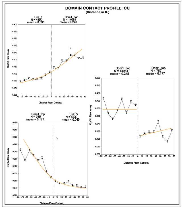
| Page | 14-11 | |
| 12/10/2012 |
| POLYMET MINING CORP. | |
| UPDATED TECHNICAL REPORT ON THE NORTHMET DEPOSIT | |
| MINNESOTA, USA |
| Figure 14-9: | Contact Profile for Magenta Zone Grade Shell (distance in ft) |

| Page | 14-12 | |
| 12/10/2012 |
| POLYMET MINING CORP. | |
| UPDATED TECHNICAL REPORT ON THE NORTHMET DEPOSIT | |
| MINNESOTA, USA |
| Figure 14-10: Grade Domains Schematic Section Looking North-East |
![]()
| Page | 14-13 | |
| 12/10/2012 |
| POLYMET MINING CORP. | |
| UPDATED TECHNICAL REPORT ON THE NORTHMET DEPOSIT | |
| MINNESOTA, USA |
| 14.4 | Grade Capping/Outlier Restrictions |
A combination of decile analysis and review of probability plots were used to determine the potential risk of grade distortion from higher-grade assays. A decile is any of the nine values that divide the sorted data into ten equal parts so that each part represents one tenth of the sample or population. In a mining project, high-grade outliers can contribute excessively to the total metal content of the NorthMet Deposit.
Typically in a decile analysis, capping is warranted if:
the last decile has more than 40% of metal, or
the last decile contains more than 2.3 times the metal quantity contained in the one before last, or
the last centile contains more than 10% of metal, or
the last centile contains more than 1.75 times the metal quantity contained in the one before last.
The decile analysis performed by the QP for the September 2007 resource model was not updated with the October 2007 dataset as very few additional data points were added. Results shown in Appendix C indicate that no grade capping is warranted for the DOM1 and Magenta Zone grade shell domains. Unit 1, Unit 20 and Units 3, 4, 5, 6 and 7 outside the Magenta Zone show significant high-grade outliers and a high-grade search restriction was considered by the QP as appropriate for the NorthMet Deposit. Table 14-3 compares the analyses and tabulates the implemented level.
| Table 14-3: | Threshold Value Used for High Grade Search Restriction (May 25, 2007 dataset) |
| Cu (%) | Ni (%) | Co (ppm) | Pt (ppb) | Pd (ppb) | Au (ppb) | S (%) | |
| Unit 20 | 0.7 | 0.18 | n/a | 200 | 1000 | 80 | 7.5 |
| Unit 1 outside DOM1 Grade shell | 1.8 | 0.6 | n/a | 450 | 1600 | 500 | 7.5 |
| DOM1 (in Unit 1) | n/a | n/a | n/a | n/a | n/a | n/a | n/a |
| DOM1 (in Unit 3) | n/a | n/a | n/a | n/a | n/a | n/a | n/a |
| Units 2/3, 4/5, 6, and 7 excluding Magenta Zone | 2.1 | 0.4 | n/a | 700 | 4000 | 500 | 8 |
| Magenta Zone | n/a | n/a | n/a | n/a | n/a | n/a | n/a |
The search restriction size was based on a next block, diamond shape pattern with a 75 ft radius from the block center. Essentially, a sample search selection ellipsoid is applied to a block during the interpolation process. Points that are above the threshold value and
| Page | 14-14 | |
| 12/10/2012 |
| POLYMET MINING CORP. | |
| UPDATED TECHNICAL REPORT ON THE NORTHMET DEPOSIT | |
| MINNESOTA, USA |
outside the smaller restricted search ellipsoid are eliminated from the set during the interpolation. Grade for the block is calculated and the process is repeated for the next block. The end result is that all high grade samples are used at face value but their range of influence is limited to an area that is more or less 75 ft in diameter
| 14.5 | Composites |
Core length statistics on the October 13 dataset indicate the sampling intervals in the two grade shell domains for the NorthMet Deposit average 5.3 ft in the DOM1 domain and 5.8 ft in the Magenta Zone. The upper third quartile shows 10 ft or less for Units 1, 3, 5, 6, 7, and 20. Based on that information a 10 ft composite length was selected. This length allowed for a few samples of greater length to be broken without affecting the variance and shorter samples to be combined to produce a sample of proper support. Summary statistics are shown in Table 14-4.
Assays were composited in 10 ft intervals starting at the toe of the hole and honouring the geological hard boundaries. Composite remnants, which are composites less than 10 ft in length, are unavoidable if the hard geological boundaries are to be honoured. The compositing methodology used by AGP locates the composite remnant (<10 ft) in Unit 20 and on the wider side of the Unit 1-Unit 3 boundary while minimizing the composite remnants in the remaining units.
| Table 14-4: | Core Length Summary Statistics (October 15 Dataset) |
| Unit Code | 30 | 20 | 1 | 3 | 5 | 6 | 7 | DOM1 | Magenta Zone |
| Number of values | 2 | 982 | 4698 | 6857 | 2189 | 845 | 427 | 15495 | 1894 |
| Minimum (ft) | 0.3 | 1.5 | 1.0 | 0.3 | 1.0 | 2.0 | 2.0 | 0.3 | 1.0 |
| Maximum (ft) | 17.0 | 12.5 | 14.0 | 12.0 | 26.0 | 12.5 | 12.0 | 17.0 | 15.0 |
| Mean (ft) | 10.0 | 5.2 | 5.2 | 6.7 | 8.3 | 8.6 | 8.9 | 5.3 | 5.8 |
| Median (ft) | 10.0 | 5.0 | 5.0 | 5.0 | 10.0 | 10.0 | 10.0 | 5.0 | 5.0 |
| First quartile (ft) | - | 5.0 | 5.0 | 5.0 | 5.0 | 7.0 | 8.0 | 5.0 | 5.0 |
| Third quartile (ft) | - | 5.0 | 5.0 | 10.0 | 10.0 | 10.0 | 10.0 | 5.0 | 5.0 |
Un-sampled intervals, gaps and assays below detection limits were composited at zero grades for copper, nickel, platinum, palladium, gold and cobalt.
For sulphur, the un-sampled intervals were initialized to the domain average value prior to compositing. A total of 1,571 sulphur intervals out of 35,402 (or 4.4% of the assay database) needed initialization. Table 14-5 shows the background value used for this resource estimate.
| Page | 14-15 | |
| 12/10/2012 |
| POLYMET MINING CORP. | |
| UPDATED TECHNICAL REPORT ON THE NORTHMET DEPOSIT | |
| MINNESOTA, USA |
| Table 14-5: | Sulphur Background Values for Unsampled Intervals |
| Domain | Sulphur Background Value |
| Unit 1 outside Domain 1 | 0.454 |
| Domain 1 | 0.668 |
| Unit 3,5,6 or 7 outside Domain 1 or Magenta zone | 0.146 |
| Magenta zone | 0.420 |
| Virginia formation | 1.230 |
| Iron formation | 0.240 |
Statistical analysis of the composite remnants indicates that intervals less than 4 ft could be safely deleted from the dataset without introducing a bias in the remaining composites. This ensured that smaller, less representative samples would not be included in the interpolation. Figure 14-11 shows an example graph for the upper DOM1 Zone where deleting composites less than four ft would only affect the metal content by 0.2%. Box plots showing statistical analysis of sample interval lengths are included in Appendix D along with the complete remnant statistical study.
| Figure 14-11: DOM1 Composite Remnants |
![]()
| Page | 14-16 | |
| 12/10/2012 |
| POLYMET MINING CORP. | |
| UPDATED TECHNICAL REPORT ON THE NORTHMET DEPOSIT | |
| MINNESOTA, USA |
Composite statistics by unit codes are shown in Table 14-6. Complete composite statistics are located in Appendix E. Composite statistics sorted by grade domain code shown in Table 14-6 and Table 14-7.
| Table 14-6: | Final Composite Statistics by Unit Code (October 2007 Dataset) | |
| Mean Grade Compilation |
| Units | 1 | 2/3 | 4/5 | 6 | 7 | 20 | 30 |
| Counts | 11,481 | 6,813 | 4,054 | 2,184 | 847 | 2,241 | 374 |
| Cu (%) | 0.201 | 0.047 | 0.057 | 0.064 | 0.015 | 0.007 | 0.001 |
| Ni (%) | 0.062 | 0.026 | 0.022 | 0.026 | 0.019 | 0.006 | 0.001 |
| Co (ppm) | 60.5 | 40.9 | 31.6 | 34.6 | 31.3 | 10.1 | 0.2 |
| Pt (ppb) | 44 | 17 | 21 | 28 | 9 | 1 | 0.5 |
| Pd (ppb) | 167 | 53 | 54 | 68 | 18 | 3 | 0.5 |
| Au (ppb) | 23 | 10 | 11 | 12 | 4 | 2 | 0.5 |
| S (%) | 0.64 | 0.17 | 0.18 | 0.17 | 0.11 | 1.40 | 0.30 |
| Page | 14-17 | |
| 12/10/2012 |
| POLYMET MINING CORP. | |
| UPDATED TECHNICAL REPORT ON THE NORTHMET DEPOSIT | |
| MINNESOTA, USA |
| Table 14-7: | Final Composites by Domain (October 15 Dataset) – Mean Grade Compilation |
| Grade Domain | Unit 1 outside DOM1 Zone | Unit 20 Virginia Formation | Code 22 Ramp Area | Code 23 | DOM1 Bot (in Unit 1) | DOM1 Top (In Unit 3) | Magenta Zone | Unit 3,4,5,6 and 7 outside Magenta Zone |
| Domain Code | 1 | 20 | 22 | 23 | 1001 | 1003 | 2000 | 3000 |
| Count | 3,192 | 2,018 | 498 | 102 | 8,158 | 423 | 1,132 | 12,155 |
| Cu% | 0.081 | 0.007 | 0.028 | 0.015 | 0.250 | 0.176 | 0.241 | 0.029 |
| Ni% | 0.029 | 0.005 | 0.014 | 0.012 | 0.075 | 0.071 | 0.066 | 0.019 |
| Cobalt ppm | 40.6 | 9.2 | 31.4 | 23.6 | 68.5 | 71.9 | 64.7 | 32.8 |
| Platinum ppb | 14 | 1 | 6 | 3 | 56 | 60 | 95 | 11 |
| Palladium ppb | 50 | 3 | 16 | 3 | 215 | 219 | 252 | 30 |
| Gold ppb | 9 | 2 | 5 | 4 | 29 | 33 | 43 | 6 |
| S% | 0.47 | 1.41 | 0.67 | 2.29 | 0.70 | 0.37 | 0.40 | 0.14 |
| Page | 14-18 | |
| 12/10/2012 |
| POLYMET MINING CORP. | |
| UPDATED TECHNICAL REPORT ON THE NORTHMET DEPOSIT | |
| MINNESOTA, USA |
| 14.6 | Variography |
Geostatisticians use a variety of tools to describe the pattern of spatial continuity, or strength of the spatial similarity of a variable with separation distance and direction. The correlogram measures the correlation between data values as a function of their separation distance and direction. If we compare samples that are close together, it is common to observe that their values are quite similar and the correlation coefficient for closely spaced samples is near 1.0. As the separation between samples increases, there is likely to be less similarity in the values and the correlogram tends to decrease toward 0.0. The distance at which the correlogram reaches zero is called the "range of correlation" or simply the range. The range of the correlogram corresponds roughly to the more qualitative notion of the "range of influence" of a sample; it is the distance over which sample values show some persistence or correlation. The shape of the correlogram describes the pattern of spatial continuity. A very rapid decrease near the origin is indicative of short scale variability. A more gradual decrease moving away from the origin suggests longer scale continuity.
Using Sage 2001 software, directional sample correlograms were calculated for all elements, copper, nickel, platinum, palladium, gold, cobalt and sulphur in each of the six grade domains along horizontal azimuths of 0, 30, 60, 90, 120, 150, 180, 210, 240, 270, 300 and 330 degrees. For each azimuth, sample correlograms were also calculated at dips of 30 and 60 degrees in addition to horizontally. Lastly, a correlogram was calculated in the vertical direction. Using the thirty-seven correlograms an algorithm determined the best-fit model. This model is described by the nugget (C0) which was derived using down hole variograms; two nested structure variance contribution (C1, C2), ranges for the variance contributions and the model type (spherical or exponential). After fitting the variance parameters, the algorithm then fits an ellipsoid to the thirty-seven ranges from the directional models for each structure. The final models of anisotropy are given by the lengths and orientations of the axes of the ellipsoids. Tables 14-8 to 14-10 summarize the results of the variography.
| Page | 14-19 | |
| 12/10/2012 |
| POLYMET MINING CORP. | |
| UPDATED TECHNICAL REPORT ON THE NORTHMET DEPOSIT | |
| MINNESOTA, USA |
| Table 14-8: | Variography DOM1 Top and Bottom (October 15 Dataset) |
| Domain | Component | Increment | Cumulative | Rotation | Angle1 | Angle2 | Angle3 | Range1 | Range2 | Range3 |
| DOM1 Bottom – Au Code 1001 | Nugget C0 | 0.036 | 0.036 | |||||||
| Exponential C1 | 0.748 | 0.784 | ZYZ | -82.94 | -72 | 45 | 14.3 | 60.8 | 3.4 | |
| Exponential C2 | 0.216 | 1 | ZYZ | -101.9 | -53 | 11 | 108.7 | 466.1 | 560.8 | |
| DOM1 Bottom – Co Code 1001 | Nugget C0 | 0.044 | 0.044 | |||||||
| Exponential C1 | 0.697 | 0.741 | ZYZ | -99.94 | 58 | 4 | 105.9 | 221.1 | 24 | |
| Exponential C2 | 0.259 | 1 | ZYZ | -135.9 | 23 | 93 | 18 | 630.2 | 773.2 | |
| DOM1 Bottom – Cu Code 1001 | Nugget C0 | 0.005 | 0.005 | |||||||
| Exponential C1 | 0.605 | 0.61 | ZYZ | -85.94 | -75 | -4 | 26.1 | 74.9 | 7.9 | |
| Exponential C2 | 0.39 | 1 | ZYZ | -202.9 | 72 | 36 | 76.1 | 611.7 | 473.7 | |
| DOM1 Bottom – Ni Code 1001 | Nugget C0 | 0.006 | 0.006 | |||||||
| Exponential C1 | 0.6 | 0.606 | ZYZ | -41.94 | 21 | 42 | 58.3 | 11 | 33.3 | |
| Exponential C2 | 0.394 | 1 | ZYZ | -84.94 | -46 | -5 | 67.4 | 488.4 | 369.3 | |
| DOM1 Bottom – Pd Code 1001 | Nugget C0 | 0.008 | 0.008 | |||||||
| Exponential C1 | 0.671 | 0.679 | ZYZ | -52.94 | 15 | -16 | 8.2 | 44.6 | 22.3 | |
| Exponential C2 | 0.321 | 1 | ZYZ | -110.9 | -51 | 12 | 103.9 | 699.9 | 441.8 | |
| DOM1 Bottom – Pt Code 1001 | Nugget C0 | 0.014 | 0.014 | |||||||
| Exponential C1 | 0.745 | 0.759 | ZYZ | -108.9 | 21 | 21 | 6.5 | 33.4 | 24.1 | |
| Exponential C2 | 0.241 | 1 | ZYZ | -150.9 | -71 | 31 | 108.3 | 494.6 | 895 | |
| DOM1 Bottom – S Code 1001 | Nugget C0 | 0.015 | 0.015 | |||||||
| Exponential C1 | 0.558 | 0.573 | ZYZ | -92.94 | -56 | 9 | 19.4 | 157.1 | 8.8 | |
| Exponential C2 | 0.427 | 1 | ZYZ | -100.9 | 52 | 51 | 162.3 | 357.3 | 56.2 | |
| DOM1 Top – Au Code 1001 | Nugget C0 | 0.013 | 0.013 | |||||||
| Exponential C1 | 0.817 | 0.83 | ZYZ | -147.9 | -33 | -39 | 38.6 | 20.3 | 9.5 | |
| Exponential C2 | 0.17 | 1 | ZYZ | -83.94 | -55 | 11 | 85.3 | 201.4 | 873.1 | |
| DOM1 Top – Co Code 1003 | Nugget C0 | 0.006 | 0.006 | |||||||
| Exponential C1 | 0.626 | 0.632 | ZYZ | -4.94 | -83 | -95 | 10.7 | 165.5 | 19.9 | |
| Exponential C2 | 0.368 | 1 | ZYZ | -66.94 | 31 | 67 | 12.1 | 2965.2 | 491.9 | |
| DOM1 Top – Cu Code 1003 | Nugget C0 | 0.028 | 0.028 | |||||||
| Exponential C1 | 0.833 | 0.861 | ZYZ | -90.94 | -79 | 61 | 17.9 | 84.7 | 5.8 | |
| Exponential C2 | 0.139 | 1 | ZYZ | -58.94 | -37 | -31 | 156.8 | 1250.9 | 648.6 | |
| DOM1 Top – Ni Code 1003 | Nugget C0 | 0.016 | 0.016 | |||||||
| Exponential C1 | 0.559 | 0.575 | ZYZ | -102.9 | -9 | -4 | 79.8 | 104.6 | 14.2 | |
| Exponential C2 | 0.425 | 1 | ZYZ | -47.94 | -1 | -32 | 40.3 | 477.2 | 253.8 | |
| DOM1 Top – Pd Code 1003 | Nugget C0 | 0.004 | 0.004 | |||||||
| Exponential C1 | 0.79 | 0.794 | ZYZ | -68.94 | -32 | 6 | 23.1 | 89.6 | 9.7 | |
| Exponential C2 | 0.206 | 1 | ZYZ | -53.94 | -54 | -21 | 81.6 | 277.2 | 1041.1 | |
| DOM1 Top – Pt Code 1003 | Nugget C0 | 0.416 | 0.416 | |||||||
| Exponential C1 | 0.391 | 0.807 | ZYZ | -88.94 | -55 | 14 | 49.9 | 207.8 | 3.7 | |
| Exponential C2 | 0.193 | 1 | ZYZ | -73.94 | -46 | -12 | 98.1 | 446.7 | 640.1 | |
| DOM1 Top – S Code 1003 | Nugget C0 | 0.061 | 0.061 | |||||||
| Exponential C1 | 0.819 | 0.88 | ZYZ | -65.94 | -69 | 0 | 37.3 | 100.5 | 9.4 | |
| Exponential C2 | 0.12 | 1 | ZYZ | -81.94 | -9 | -11 | 77.5 | 1,568.4 | 352.5 |
| Page | 14-20 | |
| 12/10/2012 |
| POLYMET MINING CORP. | |
| UPDATED TECHNICAL REPORT ON THE NORTHMET DEPOSIT | |
| MINNESOTA, USA |
| Table 14-9: | Variography Unit 1 and Unit 20 (October 15 Dataset) |
| Domain | Component | Increment | Cumulative | Rotation | Angle1 | Angle2 | Angle3 | Range1 | Range2 | Range3 |
| Unit 1 – Au Code 1 | Nugget C0 | 0.784 | 0.784 | |||||||
| Spherical C1 | 0.137 | 0.921 | ZYZ | -57.94 | 80 | -36 | 143.4 | 102.9 | 3 | |
| Spherical C2 | 0.079 | 1 | ZYZ | -151.9 | -3 | 91 | 542.1 | 12688 | 16,954 | |
| Unit 1 – Co Code 1 | Nugget C0 | 0.495 | 0.495 | |||||||
| Spherical C1 | 0.186 | 0.681 | ZYZ | -115.9 | 64 | -50 | 213.8 | 80.9 | 26.7 | |
| Spherical C2 | 0.319 | 1 | ZYZ | -89.94 | -48 | 97 | 3002.4 | 244.7 | 789.9 | |
| Unit 1 – Cu Code 1 | Nugget C0 | 0.48 | 0.48 | |||||||
| Spherical C1 | 0.265 | 0.745 | ZYZ | -100.9 | -11 | -30 | 15.6 | 95.6 | 118.3 | |
| Spherical C2 | 0.255 | 1 | ZYZ | -62.94 | 4 | 16 | 52.4 | 104.2 | 960.3 | |
| Unit 1 – Ni Code 1 | Nugget C0 | 0.647 | 0.647 | |||||||
| Spherical C1 | 0.205 | 0.852 | ZYZ | -128.9 | 85 | 48 | 155.9 | 181.5 | 10.1 | |
| Spherical C2 | 0.148 | 1 | ZYZ | -118.9 | 3 | 46 | 283.3 | 3019.2 | 1,094.7 | |
| Unit 1 – Pd Code 1 | Nugget C0 | 0.508 | 0.508 | |||||||
| Spherical C1 | 0.296 | 0.804 | ZYZ | -121.9 | 90 | 3 | 306 | 171.8 | 7.9 | |
| Spherical C2 | 0.196 | 1 | ZYZ | -66.94 | 7 | 89 | 5569.9 | 902.3 | 599.5 | |
| Unit 1 – Pt Code 1 | Nugget C0 | 0.672 | 0.672 | |||||||
| Spherical C1 | 0.234 | 0.906 | ZYZ | -122.9 | 89 | -35 | 313.8 | 213.9 | 8.1 | |
| Spherical C2 | 0.094 | 1 | ZYZ | 29.06 | -74 | 47 | 1183.8 | 765.1 | 2,754.6 | |
| Unit 1 – S Code 1 | Nugget C0 | 0.533 | 0.533 | |||||||
| Spherical C1 | 0.3 | 0.833 | ZYZ | 119.06 | 70 | -16 | 316.1 | 93.5 | 40.9 | |
| Spherical C2 | 0.167 | 1 | ZYZ | -101.9 | 39 | 8 | 218.4 | 2008.7 | 214.2 | |
| Unit 20 – Au Code 20 | Nugget C0 | 0.368 | 0.368 | |||||||
| Spherical C1 | 0.435 | 0.803 | ZYZ | -74.94 | 90 | 26 | 66.6 | 85.5 | 6.2 | |
| Spherical C2 | 0.197 | 1 | ZYZ | -55.94 | -12 | 62 | 143.8 | 79.1 | 546.8 | |
| Unit 20 – Co Code 20 | Nugget C0 | 0.398 | 0.398 | |||||||
| Spherical C1 | 0.279 | 0.677 | ZYZ | -124.9 | -62 | 81 | 48.3 | 215.9 | 11.4 | |
| Spherical C2 | 0.323 | 1 | ZYZ | -106.9 | 50 | 33 | 457 | 1,859.6 | 223.2 | |
| Unit 20 - Cu Code 20 | Nugget C0 | 0.45 | 0.45 | |||||||
| Spherical C1 | 0.381 | 0.831 | ZYZ | -94.94 | 87 | -49 | 163.5 | 152.2 | 9 | |
| Spherical C2 | 0.169 | 1 | ZYZ | -60.94 | -5 | -54 | 155.5 | 500 | 1,200 | |
| Unit 20 – Ni Code 20 | Nugget C0 | 0.406 | 0.406 | |||||||
| Spherical C1 | 0.34 | 0.746 | ZYZ | -80.94 | 90 | 3 | 182.4 | 67.1 | 7.9 | |
| Spherical C2 | 0.254 | 1 | ZYZ | -83.94 | 11 | 9 | 78.3 | 117.5 | 1,190.4 | |
| Unit 20 – Pd Code 20 | Nugget C0 | 0.571 | 0.571 | |||||||
| Spherical C1 | 0.198 | 0.769 | ZYZ | -68.94 | 61 | -55 | 44.1 | 140.4 | 163.5 | |
| Spherical C2 | 0.231 | 1 | ZYZ | -14.94 | 0 | -24 | 5.4 | 50.9 | 609 | |
| Unit 20 – Pt Code 20 | Nugget C0 | 0.434 | 0.434 | |||||||
| Spherical C1 | 0.402 | 0.836 | ZYZ | -47.94 | 89 | -47 | 81.3 | 52.1 | 4.9 | |
| Spherical C2 | 0.164 | 1 | ZYZ | -39.94 | 3 | 82 | 179.3 | 76.5 | 759.2 | |
| Unit 20 – S Code 20 | Nugget C0 | 0.227 | 0.227 | |||||||
| Spherical C1 | 0.389 | 0.616 | ZYZ | -150.9 | 28 | 3 | 28.4 | 60.8 | 138.8 | |
| Spherical C2 | 0.384 | 1 | ZYZ | -48.94 | 0 | 13 | 47.9 | 105.4 | 1,410.5 |
| Page | 14-21 | |
| 12/10/2012 |
| POLYMET MINING CORP. | |
| UPDATED TECHNICAL REPORT ON THE NORTHMET DEPOSIT | |
| MINNESOTA, USA |
Table 14-10: Variography Magenta Zone and Code 3000 (October 15 Dataset)
| Domain | Component | Increment | Cumulative | Rotation | Angle1 | Angle2 | Angle3 | Range1 | Range2 | Range3 |
| Magenta Zone – Au Code 2000 | Nugget C0 | 0.004 | 0.004 | |||||||
| Exponential C1 | 0.796 | 0.8 | ZYZ | -47.94 | 41 | -57 | 34.7 | 77.2 | 13.1 | |
| Exponential C2 | 0.2 | 1 | ZYZ | -102.9 | -69 | 3 | 48.5 | 1609.1 | 469.9 | |
| Magenta Zone – Co Code 2000 | Nugget C0 | 0.003 | 0.003 | |||||||
| Exponential C1 | 0.695 | 0.698 | ZYZ | -68.94 | 83 | -14 | 16.6 | 91.5 | 8.6 | |
| Exponential C2 | 0.302 | 1 | ZYZ | -91.94 | 35 | 48 | 1415.2 | 297.2 | 134.7 | |
| Magenta Zone – Cu Code 2000 | Nugget C0 | 0.004 | 0.004 | |||||||
| Exponential C1 | 0.81 | 0.814 | ZYZ | -10.94 | 20 | -54 | 170.1 | 67.4 | 19.9 | |
| Exponential C2 | 0.186 | 1 | ZYZ | -87.94 | -53 | -4 | 26.4 | 1004.3 | 911.1 | |
| Magenta Zone – Ni Code 2000 | Nugget C0 | 0.006 | 0.006 | |||||||
| Exponential C1 | 0.816 | 0.822 | ZYZ | -12.96 | 27 | -63 | 156.4 | 89 | 19 | |
| Exponential C2 | 0.178 | 1 | ZYZ | -88.9 | -53 | -3 | 28.7 | 1396.2 | 424.5 | |
| Magenta Zone – Pd Code 2000 | Nugget C0 | 0.003 | 0.003 | |||||||
| Exponential C1 | 0.744 | 0.747 | ZYZ | -63.94 | 57 | 11 | 35.5 | 79.1 | 11.5 | |
| Exponential C2 | 0.253 | 1 | ZYZ | -5.94 | -88 | -25 | 60.2 | 272.8 | 1068.1 | |
| Magenta Zone - Pt Code 2000 | Nugget C0 | 0.004 | 0.004 | |||||||
| Exponential C1 | 0.727 | 0.731 | ZYZ | -59.94 | 59 | 8 | 28.3 | 103.7 | 1.9 | |
| Exponential C2 | 0.269 | 1 | ZYZ | -105.9 | -74 | 2 | 33.1 | 937.5 | 246.1 | |
| Magenta Zone – S Code 2000 | Nugget C0 | 0.082 | 0.082 | |||||||
| Exponential C1 | 0.723 | 0.805 | ZYZ | -4.94 | 21 | -97 | 149.2 | 87.1 | 19 | |
| Exponential C2 | 0.195 | 1 | ZYZ | -88.94 | -68 | -2 | 26.5 | 551.9 | 332.2 | |
| Unit 3, 4, 5, 6, 7 – Au Code 3000 | Nugget C0 | 0.3 | 0.3 | |||||||
| Exponential C1 | 0.7 | 1 | ZYZ | 5.06 | -22 | 18 | 210.6 | 78.5 | 20.2 | |
| Unit 3, 4, 5, 6, 7 – Co Code 3000 | Nugget C0 | 0.152 | 0.152 | |||||||
| Exponential C1 | 0.848 | 1 | ZYZ | -5.94 | 0 | 7 | 101.9 | 17.2 | 1321.8 | |
| Unit 3, 4, 5, 6, 7 – Cu Code 3000 | Nugget C0 | 0.006 | 0.006 | |||||||
| Exponential C1 | 0.994 | 1 | ZYZ | 69.06 | 20 | -55 | 410 | 29.7 | 21 | |
| Unit 3, 4, 5, 6, 7 – Ni Code 3000 | Nugget C0 | 0.142 | 0.142 | |||||||
| Exponential C1 | 0.858 | 1 | ZYZ | 12.06 | -13 | -11 | 318.9 | 19.4 | 58.2 | |
| Unit 3, 4, 5, 6, 7 – Pd Code 3000 | Nugget C0 | 0.4 | 0.4 | |||||||
| Exponential C1 | 0.6 | 1 | ZYZ | -47.94 | 25 | 31 | 216.2 | 66.1 | 27.7 | |
| Unit 3, 4, 5, 6, 7 – Pt Code 3000 | Nugget C0 | 0.133 | 0.133 | |||||||
| Exponential C1 | 0.867 | 1 | ZYZ | -11.94 | 37 | -14 | 133.4 | 87.8 | 9.8 | |
| Unit 3, 4, 5, 6, 7 – S Code 3000 | Nugget C0 | 0.011 | 0.011 | |||||||
| Exponential C1 | 0.989 | 1 | ZYZ | 79.06 | 18 | -55 | 176.4 | 56.9 | 28.2 |
| Page | 14-22 | |
| 12/10/2012 |
| POLYMET MINING CORP. | |
| UPDATED TECHNICAL REPORT ON THE NORTHMET DEPOSIT | |
| MINNESOTA, USA |
Generally, ranges for the copper correlogram in the main DOM1 grade shell reach 1,000 ft at approximately 96% of the 1.0 sill level in the main strike direction as shown in Figure 14-12.
| Figure 14-12: Copper Correlogram for Domain 1001 – Main Strike Direction |
![]()
In the down dip direction, the range is shorter reaching about 800 ft at about 96% of the sill value as shown in Figure 14-13. The variography indicate good continuity in the grade distribution, the contact profile show a good marker horizon exists between unit 1 and unit 3 which is consistent with PolyMet’s NorthMet field geologists being able to predict the location of the high grade horizon with a relatively good degree of accuracy prior to drilling.
| Figure 14-13: Copper Correlogram for Domain 1001 - Down Dip Direction |
![]()
| Page | 14-23 | |
| 12/10/2012 |
| POLYMET MINING CORP. | |
| UPDATED TECHNICAL REPORT ON THE NORTHMET DEPOSIT | |
| MINNESOTA, USA |
The Magenta Zone show shorter ranges with a maximum range of 800 ft at the sill in the main strike direction and 500 ft in the down dip direction.
Domain 1003 did not provide enough points to generate a reliable correlogram and AGP elected to use the lithological Unit 3 points for the spatial analysis in lieu of the domain 1003 points.
The complete spatial analysis is attached in Appendix F.
| 14.7 | Density Assignment |
PolyMet’s October 15, 2007 database contains 6,997 specific gravity/density measurements.
Mark J. Severson et al., Natural Resources Research Institute of the University of Minnesota, Duluth compiled 1,037 comparative specific gravity (SG) determinations in 1999-2000 using Jolly balance determinations on smaller pieces and duplicate measurements of displacement and weight (“graduated cylinder method”) on larger core pieces.
From this work, Severson reported the following:
When compared to the Jolly Balance method, the Graduated Cylinder method is not onlyfaster (about 25 samples per hour, versus the Jolly Balance’s 30-40 samples per day), but just as accurate.
and subsequently concluded:
In most cases, sample variance is smaller for the Graduated Cylinder method than the Jolly Balance method, probably because the Graduated Cylinder method uses a much larger sample. This sheer difference in specimen size makes the Graduated Cylinder samples more robust to minor variations. Furthermore, the relatively simple nature of the Graduated Cylinder method reduces the chance for introducing measurement errors.
PolyMet used primarily the Graduated Cylinder method for subsequent specific gravity determination. The distribution of the data including all determinations in the database is shown in Table 14-11.
| Table 14-11: | Percentage of Specific Gravity Determination by Method (October 15 Dataset) |
| Method | Percent of Total Determination | Average SG |
| PolyMet Graduated Cylinder | 82 | 2.93 |
| PolyMet Weight in Water | 3 | 2.95 |
| Severson/Zanko Data - Graduated Cylinder | 14 | 2.92 |
| Severson/Zanko Data - Jolly Balance | 1 | 2.93 |
| Chemex (average) | 0.1 | 2.91 |
| Page | 14-24 | |
| 12/10/2012 |
| POLYMET MINING CORP. | |
| UPDATED TECHNICAL REPORT ON THE NORTHMET DEPOSIT | |
| MINNESOTA, USA |
Density measurements to date have been made on core that has not been oven dried and has not been sealed. This is likely to have resulted in a small (~1%) overstatement due to the inclusion of moisture that would normally be driven off at 105 to 110°C. It is recommended that approximately 50 samples be selected and the weight loss be determined after drying for the same temperature and duration as used by the assay laboratory.
The QP considered the specific gravity determination using the graduated cylinder method to be accurate enough to use in the resource estimation.
Table 14-12 list the average specific gravity determination including all determination (October 2007 dataset) sorted by unit.
| Table 14-12: | Specific Gravity Average per Unit (October 15 Dataset) |
| Unit | Mean | Count |
| 1 | 2.98 | 2,381 |
| 3 (2+3) | 2.92 | 1,818 |
| 5 (4+5) | 2.90 | 1,266 |
| 6 | 2.90 | 902 |
| 7 | 2.92 | 326 |
| 20 | 2.77 | 273 |
| 30 | 3.17 | 9 |
| All Units | 2.93 | 6,975 |
| 14.8 | Resource Model Definition |
One block model was constructed in Gemcom’s GEMS version 6.04™ software. The block size was 50 ft by 50 ft by 20 ft to allow for detailed engineering of the resource model.
The block model matrix was defined using the following coordinates (block edge) based on the Minnesota State Plane Grid (North Zone, NAD83, NAVD 88):
| Easting: | 2,896,240.59081 | ||
| Northing: | 728,838.73616 | ||
| Top elevation: | 1,620 | ||
| Number of blocks in the X direction: 399 | |||
| Number of blocks in the Y direction: 122 | |||
| Number of blocks in the Z direction: 81 | |||
| Page | 14-25 | |
| 12/10/2012 |
| POLYMET MINING CORP. | |
| UPDATED TECHNICAL REPORT ON THE NORTHMET DEPOSIT | |
| MINNESOTA, USA |
The model is rotated 33.94 degrees counter-clockwise around the origin giving the model X direction an azimuth of 56.06 degree. The block model matrix covers the area bounded by the coordinates listed in Table 14-13.
| Table 14-13: | Maximum and Minimum Coverage for the Block Model Matrix (edge to edge) |
| Coordinate | Minimum | Maximum |
| Easting | 2892834.810 | 2912791.563 |
| Northing | 728838.736 | 745038.007 |
| Elevation | 0.00 | 1620 |
A unit model was assigned a code corresponding to the integer code of the lithological units. Blocks in this model have a value of 30, 20, 1, 3, 5, 6, or 7. A domain model was coded using the DOM1SOL, MAGZONE, and two Virginia Formation inclusions wireframe named CODE21 and RAMP-07 in the database. Blocks in this model have values of 1000 for the DOM1 grade shell, 2000 for the Magenta Zone grade shell, and 21 or 23 for the two major Virginia Formation inclusions. The final grade domain code was calculated in the Rocktype model using a block model manipulation script where the block integer code was assigned according to the matrix in Table 14-14 and illustrated in Figure 14-14 graphically.
| Table 14-14: | Grade Domain Coding Matrix |
Domain Code | Unit Code | ||||||
| 30 | 20 | 1 | 3 (2+3) | 5 (4+5) | 6 | 7 | |
| - | 30 | - | - | - | - | - | - |
| - | - | 20 | - | - | - | - | - |
| 23 | 23 | 23 | 23 | 23 | 23 | 23 | 23 |
| 22 | 22 | 22 | 22 | 22 | 22 | 22 | 22 |
| 1000 | - | - | 1,001 | 1,003 | - | - | - |
| 2000 | - | - | 2,000 | 2,000 | 2,000 | 2,000 | 2,000 |
| 3000 | - | - | - | 3,000 | 3,000 | 3,000 | 3,000 |
| Page | 14-26 | |
| 12/10/2012 |
| POLYMET MINING CORP. | |
| UPDATED TECHNICAL REPORT ON THE NORTHMET DEPOSIT | |
| MINNESOTA, USA |
| Figure 14-14: Final Grade Domain Code in the Gemcom© Rocktype Model |
![]()
| Page | 14-27 | |
| 12/10/2012 |
| POLYMET MINING CORP. | |
| UPDATED TECHNICAL REPORT ON THE NORTHMET DEPOSIT | |
| MINNESOTA, USA |
| 14.9 | Interpolation Plan |
Interpolation was carried out in five passes with an increasing search radius coupled with a decreasing sample density restriction. The interpolation plan used for the NorthMet Deposit allows for a limited soft boundary across the grade shell domain DOM1 and its surrounding unit code. The soft boundary search was limited to the most restrictive Pass 1 search in order to avoid high grade smearing into the lower grade areas or vice versa, as the search ellipsoid becomes larger in the subsequent passes. With the exception of DOM1 grade shell boundary, the remaining grade domains were treated as hard boundaries.
The search ellipsoids orientation and dip were tweaked in this resource estimate to coincide better with the average strike and dip angle of the NorthMet Deposit. Grade shell DOM1 shows an average azimuth of 59.6° and dips towards the southeast at 28.6°. The Magenta Zone is flatter, exhibiting a strike of 51.7° dipping southeast at 14.5°. Units 1 and 20 were kept at the average deposit strike of 56.06° and dipping southeast at 30°.
Search ranges were based on the density of diamond drilling and the two main ore domain copper correlograms. Generally, the ratio between the major and semi-minor axis is 0.56 while the ratio between the semi-minor and minor axis was kept around 0.23 for Pass 1 to Pass 4 inclusively. The incremental ratio of the major axis between passes was 0.5, 0.66 and 0.45 respectively for Pass 1 to Pass 2, Pass 2 to Pass 3 and Pass 3 to Pass 4.
Table 14-15 summarizes the ellipsoid dimensions used in the different passes while Table 14-16 summarizes the search angle and search restriction imposed on the high grade outliers as described in the capping section (Section 14-4) of this report.
A series of model in the block matrix called Nbsamp1, Nbsamp2, Nbsamp3 and Nbsamp4 recorded the number of samples used to interpolate the blocks. These models were used in a block manipulation script to fill a PassNb model with a value of 1, 2, 3 or 4 representing at what pass a given grade was interpolated.
The target domain code and sample code controls the soft/hard boundary of the model. When a block is interpolated with a given target domain code the software will load the point file according to the grid listed in Table 14-17 and Table 14-18.
| Table 14-15: | Ellipsoid Dimensions |
| Ellipsoid dimension ( in ft) | Number of Samples Used | ||||||
| X | Y | Z | Min | Max | Max per hole | Comment | |
| Pass 1 | 300 | 170 | 40 | 6 | 15 | 5 | Minimum of two holes required |
| Pass 2 | 600 | 340 | 80 | 6 | 15 | 5 | Minimum of two holes required |
| Pass 3 | 900 | 500 | 115 | 2 | 15 | 5 | |
| Page | 14-28 | |
| 12/10/2012 |
| POLYMET MINING CORP. | |
| UPDATED TECHNICAL REPORT ON THE NORTHMET DEPOSIT | |
| MINNESOTA, USA |
| Ellipsoid dimension ( in ft) | Number of Samples Used | ||||||
| Pass 4 | 2,000 | 1,100 | 265 | 2 | 15 | 5 | |
| Pass 5 | 8,000 | 6,000 | 1,200 | 2 | 15 | 5 | Use to fill un-interpolated blocks |
| Table 14-16: | Sample Search Parameters (all passes) |
| Search Angle | Search Restriction Size and High Grade Threshold Value Used | |||||||||||
| Z | X | Z | Z | X | Z | Au (ppb) | Cu (%) | Ni (%) | Pd (ppb) | Pt (ppb) | S (%) | |
| Dom 20, 22, 23 | 0 | 30 | 0 | 75 | 75 | 75 | 80 | 0.7 | 0.18 | 1000 | 200 | 7.5 |
| Dom 1 | -6 | 29 | 0 | 75 | 75 | 75 | 500 | 1.8 | 0.6 | 1600 | 450 | 7.5 |
| Dom 1001 | -6 | 29 | 0 | n/a | n/a | n/a | n/a | n/a | n/a | n/a | n/a | n/a |
| Dom 1003 | -6 | 29 | 0 | n/a | n/a | n/a | n/a | n/a | n/a | n/a | n/a | n/a |
| Dom 3000 | -5 | 18 | 0 | 75 | 75 | 75 | 500 | 2.1 | 0.4 | 4000 | 700 | 8 |
| Dom 2000 | 4 | 15 | 0 | n/a | n/a | n/a | n/a | n/a | n/a | n/a | n/a | n/a |
| Table 14-17: | Pass 1 – Target Domain Code and Sample Code Used |
| 20 | 1 | 1001 | 1003 | 3000 | 2000 | 22 | 23 | |
| 20 | x | |||||||
| 1 | x | x | ||||||
| 1001 | x | x | ||||||
| 1003 | x | x | ||||||
| 3000 | x | x | ||||||
| 2000 | x | |||||||
| 22 | x | |||||||
| 23 | x |
| Table 14-18: | Pass 2, 3, 4 and 5 – Target Domain Code Sample Code Used |
| 20 | 1 | 1001 | 1003 | 3000 | 2000 | 22 | 23 | |
| 20 | x | |||||||
| 1 | x | |||||||
| 1001 | x | |||||||
| 1003 | x | |||||||
| 3000 | x | |||||||
| 2000 | X | |||||||
| 22 | x | |||||||
| 23 | x |
| Page | 14-29 | |
| 12/10/2012 |
| POLYMET MINING CORP. | |
| UPDATED TECHNICAL REPORT ON THE NORTHMET DEPOSIT | |
| MINNESOTA, USA |
The density model was initialized with the unit average density from Table 14-18. The density data collected by PolyMet was interpolated into the model using a simple inverse distance model with a fairly restrictive search ellipse of 300 ft x 300 ft x 75 ft. The minimum number of samples was set to six, the maximum was fifteen and a maximum of five samples per hole was imposed. In total, 3.22% of all the blocks in the model were interpolated by the inverse distance method.
| 14.9.1 | Minor Elements |
AGP carried out a geostatistical study of the elements that may have a measurable effect on stockpile drainage water quality for waste characterization and environmental purposes. The thirteen elements analyzed were silver, arsenic (As), barium (Ba), beryllium (Be), cadmium (Cd), chromium (Cr), manganese (Mn), molybdenum (Mo), phosphorus (P), lead, antimony (Sb), vanadium (V), zinc (Zn). The water quality elements grades were interpolated using an inverse distance square technique in a separate block model in GEMS version 6.04. The model matrix was replicated from the main resource grade model and thus occupies the same space.
| 14.10 | Classification of Mineral Resources |
Several factors are considered in the definition of a resource classification:
Canadian Institute of Mining (CIM) requirements and guidelines
experience with similar deposits
spatial continuity
confidence limit analysis
geology
No environmental, permitting, legal, title, taxation, socio-economic, marketing or other relevant issues are known to the author that may affect the estimate of mineral resources. Mineral resources tabulated in section 14-11, are not mineral reserves and do not have demonstrated economic viability. Reserves can only be estimated on the basis of an economic evaluation that are used in a Pre-Feasibility or Feasibility Study of a mineral project and are tabulated in section 15-3 of this report.
Four confidence categories exist in the model. The usual CIM guidelines of Measured, Indicated and Inferred classes are coded 1, 2 and 3 respectively. A special code 4 called “Fill” in this report represents what are typically un-interpolated blocks. NorthMet requires that all blocks in the model carry sulphur value in addition to the six primary grade elements for environmental purposes and therefore a fourth and fifth pass was used, with a large search ellipsoid, so that all blocks in the model are populated with a grade value.
| Page | 14-30 | |
| 12/10/2012 |
| POLYMET MINING CORP. | |
| UPDATED TECHNICAL REPORT ON THE NORTHMET DEPOSIT | |
| MINNESOTA, USA |
Typically, confidence level for a grade in the block model is reduced with the increase in the search ellipsoid size along with the diminishing restriction on the number of samples used for the grade interpolation. This is essentially controlled via the pass number of the interpolation plan describe in the previous section. A common technique is to categorize a model based on the pass number and distance to the closest sample. In numeric models with hard boundaries between grade domains the technique has a tendency to stripe the model with measured category in close proximity with inferred category. If the interpolation uses a minimum number of holes similar to pass 1 and pass 2 in the current model, this effect can be aggravated showing an indicated category in between drill holes where a series of blocks were interpolated with the pass 1 with a minimum of 2 drill holes restriction while the blocks located directly on the drillholes could not see the next hole end up classified as inferred.
For the NorthMet Deposit, AGP elected to classify the mineral resource primarily using the Pass number from the interpolation plan with help from a core area model to minimize having blocks in the measured category in close proximity with blocks in the inferred category.
The core area model represents the density of the drilling in the resource model based on two components; the position of the drillholes and the number of drillholes surrounding the blocks in the matrix. The model was created as follows:
A model in the block model matrix called DDH175 was first created by assigning the percentage of the blocks inside a 175 ft extruded drillhole trace. The model was then interpolated with a inverse distance methodology using octant search with a round ellipse of 300 ft x 300 ft x 60 ft in order to fill the spaces in the immediate vicinity of the drill hole 175 ft extruded trace. The model contains values from 0 to 100% representing how far a block center is from a 175 ft extruded drillhole trace where 100% means the block is fully within the trace of the drillhole shown in the top right inset image of Figure 14-15.
A second model called NBHoles was created in the block model matrix containing the same number of drillholes that are visible from a given block in the model within a 300 ft search bubble. The model contains values from 0 to 15 representing the number of drillholes visible within a 300 ft search bubble from the block center shown in the bottom left inset of Figure 14-15.
A third and final model called Core was constructed in the block model matrix containing the combination of the DDH175 model and the NBHoles model weighted at a 25/75 ratio between the DDH175 and NBHoles model respectively. This procedure essentially eliminated the stripping effect visible in the DDH175 model for holes near the fringe area of the core while giving more weight to the number of drillholes visible from a block center. The resulting model carries an empirical value from 0 to 81.25 (average 7.131) describing more or less the number of drillholes visible to a block center in relation to the proximity to the nearest hole. A high value is well within the
| Page | 14-31 | |
| 12/10/2012 |
| POLYMET MINING CORP. | |
| UPDATED TECHNICAL REPORT ON THE NORTHMET DEPOSIT | |
| MINNESOTA, USA |
core area drilled by PolyMet’s NorthMet staff geologists while a low value is near the fringe. The core area values are shown in the main image Figure 14-15.
| Page | 14-32 | |
| 12/10/2012 |
| POLYMET MINING CORP. | |
| UPDATED TECHNICAL REPORT ON THE NORTHMET DEPOSIT | |
| MINNESOTA, USA |
| Figure 14-15: Core Area with Drillhole Traces |
![]()
| Page | 14-33 | |
| 12/10/2012 |
| POLYMET MINING CORP. | |
| UPDATED TECHNICAL REPORT ON THE NORTHMET DEPOSIT | |
| MINNESOTA, USA |
| Figure 14-16: Section 35700ME Classification Model |
![]()
| Page | 14-34 | |
| 12/10/2012 |
| POLYMET MINING CORP. | |
| UPDATED TECHNICAL REPORT ON THE NORTHMET DEPOSIT | |
| MINNESOTA, USA |
The category model was coded using the pass number to define the Measured, Indicated and Inferred category in combination with the core area model as per schedule in Table 14-9 where a block located outside the core area was likely to be downgraded in category. The procedure allowed the fine tuning of the measured category.
Table 14-19 summarizes the classification parameters used for the category models. Based on the criteria outlined in
Table 14-20, 3% of the blocks estimated at the NorthMet project are classified as Measured, 14% of the blocks are Indicated and 22% of the blocks are Inferred. The remaining blocks are either non-interpolated, category 4 or “fill.” Figure 14-6 shows a representative section of the category model.
| Table 14-19: | Classification Parameters |
| Pass Number | Inside Core | Outside Core |
| Pass 1 | Measured if Core value > 75 | Indicated |
| Pass 2 | Indicated | Indicated |
| Pass 3 | Indicated | Inferred |
| Pass 4 | Inferred | Fill |
| Pass 5 | Fill | Fill |
| Table 14-20: | NorthMet Project Category Model Tabulation |
Unit | Total No. of Blocks | Measured | Indicated | Inferred | Non-Interpolated or Fill | ||||
| No. of Blocks | % | No. of Blocks | % | No. of Blocks | % | No. of Blocks | % | ||
| 20, 1, 3, 5, 6, 7 | 2,829,567 | 109,992 | 3 | 560,643 | 14 | 880,740 | 22 | 1,278,192 | 32 |
| 30 or Air | 1,113,351 | - | 0 | - | 0 | - | 0 | 1,113,351 | 28 |
| Total Block | 3,942,918 | ||||||||
| 14.10.1 | Net Metal Value Formula |
For comparison purposes, AGP was requested by PolyMet to use the same metal price and recovery figures used previously in the report titled “Technical Report on the Results of a Definitive Feasibility Study of the NorthMet Project” authored by D.J. Hunter and dated October 2006 and also used in the September 2007 resource model.
Net Metal Value is calculated as follows:
| 1) | For all elements a net metal price is calculated: |
| Page | 14-35 | |
| 12/10/2012 |
| POLYMET MINING CORP. | |
| UPDATED TECHNICAL REPORT ON THE NORTHMET DEPOSIT | |
| MINNESOTA, USA |
Net Metal Price = (Metal price - Refining, insurance and transport charge)
| 2) | For each element, a factor is calculated: |
| a) | For Copper and Nickel (expressed in %): |
Factor = Net Metal Price * Recovery Ore to Conc. * Recovery Conc. To Metal * Conversion % to lbs
| b) | For Cobalt (expressed in ppm): |
Factor = Net Metal Price * Recovery Ore to Conc. * Recovery Conc. To Metal * Conversion ppm to % * Conversion % to lbs
| c) | For Platinum, Palladium and Gold (expressed in ppb): |
Factor = Net Metal Price * Recovery Ore to Conc. * Recovery Conc. To Metal * Conversion ppb to ppm * Conversion ppm to troy oz
| 3) | For all elements, the value per tonne is calculated in US$: |
Value/tons = grade * factor
| 4) | Total NMV is the addition of the Value per tons for each element: |
NMV = Value/tons Cu + Value/tons Ni + Value/tons Co + Value/tons Pt + Value/tons Pd + Value/tons Au
Table 14-21 lists the price, recoveries, refining, insurance and transportation charge used in the calculation. Conversion factors used are:
percent to pounds per short ton multiply by 20
ppm to percent multiply by 0.0001
ppb to ppm multiply by 0.001
ppm to troy ounces multiply by 0.02917 or (1/34.285).
| Table 14-21: | NMV Input Parameters |
Metal in Model | Unit | Metal Price ($) | Refining, Insurance and Transport ($) | Recovery Ore – Concentrate | Recovery Concentrate – Metal |
| Copper (%) | US$/lb | 1.25 | 0.00 | 0.9420 | 0.980 |
| Nickel (%) | US$/lb | 5.60 | 1.40 | 0.7250 | 0.970 |
| Cobalt (ppm) | US$/lb | 15.25 | 6.10 | 0.4200 | 0.970 |
| Platinum (ppb) | US$/troy oz | 800.00 | 18.00 | 0.7690 | 0.945 |
| Palladium (ppb) | US$/troy oz | 210.00 | 17.00 | 0.7960 | 0.945 |
| Gold (ppb) | US$/troy oz | 400.00 | 9.50 | 0.7570 | 0.885 |
| Page | 14-36 | |
| 12/10/2012 |
| POLYMET MINING CORP. | |
| UPDATED TECHNICAL REPORT ON THE NORTHMET DEPOSIT | |
| MINNESOTA, USA |
| 14.11 | Mineral Resource Tabulation |
Table 14-22 shows resources below the overburden bottom surface to 0.00 elevation for Unit 20, 1, 3 (2+3), 5 (4+5), 6 and 7. The base case is using a cut-off grade of 0.2% copper.
| Table 14-22: | Resource Model Summary at 0.2% Cu Cut-off |
| Cut-off @ 0.2% Cu | Volume (M ft3) | Density (st/ft3) | Tonnage (M st) | Cu (%) | Ni (%) | S (%) | Pt (ppb) | Pd (ppb) | Au (ppb) | Co (ppm) |
| Measured | 1,530.3 | 0.093 | 141.9 | 0.338 | 0.094 | 0.81 | 81 | 301 | 42 | 77 |
| Indicated | 3,244.0 | 0.093 | 300.2 | 0.318 | 0.087 | 0.78 | 81 | 287 | 41 | 72 |
| M+I | 4,774.3 | 0.093 | 442.1 | 0.325 | 0.089 | 0.79 | 81 | 292 | 41 | 73 |
| Inferred | 1,712.8 | 0.093 | 158.7 | 0.329 | 0.088 | 0.73 | 86 | 315 | 43 | 55 |
Table 14-23 shows the resource sensitivity to changes in cut-off with the base case cut-off highlighted.
| Page | 14-37 | |
| 12/10/2012 |
| POLYMET MINING CORP. | |
| UPDATED TECHNICAL REPORT ON THE NORTHMET DEPOSIT | |
| MINNESOTA, USA |
| Table 14-23: | Cumulative Resource Model Results at Various Cu % Cut-offs (for sensitivity only) |
Cut-off | Volume (M ft3) | Density (st/ft3) | Tonnage (M st) | Cu (%) | Ni (%) | S (%) | Pt (ppb) | Pd (ppb) | Au (ppb) | Co (ppm) |
| Measured | ||||||||||
| >0.5 | 126.1 | 0.093 | 11.7 | 0.574 | 0.140 | 1.08 | 124 | 485 | 62 | 89 |
| >0.4 | 395.8 | 0.093 | 36.7 | 0.485 | 0.125 | 1.01 | 108 | 417 | 55 | 86 |
| >0.3 | 852.5 | 0.093 | 79.1 | 0.411 | 0.110 | 0.93 | 95 | 360 | 49 | 82 |
| >0.2 | 1530.3 | 0.093 | 141.9 | 0.338 | 0.094 | 0.81 | 81 | 301 | 42 | 77 |
| >0.1 | 2529.3 | 0.093 | 234.4 | 0.263 | 0.077 | 0.67 | 64 | 232 | 33 | 71 |
| Indicated | ||||||||||
| >0.5 | 207.2 | 0.093 | 19.2 | 0.577 | 0.131 | 1.04 | 138 | 509 | 69 | 80 |
| >0.4 | 629.8 | 0.093 | 58.3 | 0.487 | 0.117 | 0.97 | 119 | 438 | 61 | 77 |
| >0.3 | 1503.5 | 0.093 | 139.2 | 0.404 | 0.103 | 0.89 | 100 | 365 | 51 | 74 |
| >0.2 | 3244.0 | 0.093 | 300.2 | 0.318 | 0.087 | 0.78 | 81 | 287 | 41 | 72 |
| >0.1 | 7078.7 | 0.092 | 654.2 | 0.223 | 0.066 | 0.65 | 54 | 187 | 29 | 66 |
| Inferred | ||||||||||
| >0.5 | 137.4 | 0.093 | 12.8 | 0.607 | 0.139 | 1.04 | 160 | 635 | 85 | 66 |
| >0.4 | 349.3 | 0.093 | 32.4 | 0.512 | 0.119 | 0.91 | 139 | 531 | 72 | 62 |
| >0.3 | 875.8 | 0.093 | 81.3 | 0.411 | 0.105 | 0.83 | 108 | 407 | 53 | 58 |
| >0.2 | 1712.8 | 0.093 | 158.7 | 0.329 | 0.088 | 0.73 | 86 | 315 | 43 | 55 |
| >0.1 | 3133.6 | 0.092 | 289.6 | 0.246 | 0.068 | 0.62 | 62 | 221 | 32 | 52 |
Table 14-24 reports resources above an elevation of 0.00 ft using an NMV value of US$7.42 derived from the same metal prices and recoveries used previously in the Hunter, 2006 report and also in the Wardrop resource model dated September 2007.
| Page | 14-38 | |
| 12/10/2012 |
| POLYMET MINING CORP. |  |
| UPDATED TECHNICAL REPORT ON THE NORTHMET DEPOSIT | |
| MINNESOTA, USA |
| Table 14-24: | Resource Model Summary at US$7.42 NMV |
| Cut-off @ US$7.42 NMV | Volume (M ft3) | Density (st/ft3) | Tonnage (M st) | Cu (%) | Ni (%) | S (%) | Pt (ppb) | Pd (ppb) | Au (ppb) | Co (ppm) | NMV (US$) |
| Measured | 2,185.03 | 0.093 | 202.5 | 0.285 | 0.083 | 0.71 | 71 | 258 | 36 | 74 | 14.58 |
| Indicated | 5,319.88 | 0.093 | 491.7 | 0.256 | 0.075 | 0.69 | 66 | 231 | 34 | 70 | 13.20 |
| M+I | 7,504.91 | 0.093 | 694.2 | 0.265 | 0.077 | 0.69 | 68 | 239 | 35 | 71 | 13.60 |
| Inferred | 2,484.53 | 0.092 | 229.7 | 0.273 | 0.079 | 0.65 | 73 | 263 | 37 | 56 | 13.97 |
| 14.12 | Block Model Validation |
The NorthMet grade models were validated by two methods:
Visual comparison of colour-coded block model grades with composite grades on section plots.
Comparison of the global mean block grades for ordinary kriging, inverse distance, nearest neighbour models, composite grades and raw assay grades.
| 14.12.1 | Visual Comparisons |
The visual comparisons of block model grades with composite grades show a reasonable correlation between the values. No significant discrepancies were apparent from the sections reviewed. | |
| 14.12.2 | Global Comparisons |
The grade statistics for the raw assay grade, composite grade, ordinary kriging, nearest neighbour and inverse distance models, are tabulated below in Table 14-25. Figures 14-17 and 14-18 show the differences. Grade statistics for composite mean grade compared to raw assay grade indicated a normal reduction in values for all elements. The block model mean grade when compared against the composites also indicated a normal reduction in values for all elements. | |
Percent changes in metal content shown in Table 14-26 between the nearest neighbour, inverse distance and ordinary kriging model are in very close agreement among all three methods with less than 2.0% difference in all elements except for cobalt showing 3.1% difference between the ordinary krig model and the nearest neighbour model. |
| Page | 14-39 |  |
| 12/10/2012 |
| POLYMET MINING CORP. | |
| UPDATED TECHNICAL REPORT ON THE NORTHMET DEPOSIT | |
| MINNESOTA, USA |
Table 14-25: Global Grade Comparison at 0.00 Cu% Cut-off
| Source | Cu (%) | Ni (%) | S (%) | Pt (ppb) | Pd (ppb) | Au(ppb) | Co(ppm) | |
| Assay | 0.160 | 0.055 | 0.44 | 40 | 140 | 21 | 62 | |
| Composite | 0.119 | 0.041 | 0.38 | 31 | 105 | 16 | 47 | |
| Block NN with MII* | 0.059 | 0.023 | 0.26 | 16 | 51 | 8 | 30 | |
| Block ID with MII | 0.060 | 0.024 | 0.26 | 16 | 51 | 8 | 30 | |
| Block OK with MII | 0.060 | 0.024 | 0.26 | 16 | 51 | 8 | 31 | |
| Block OK with MIIF* | 0.052 | 0.022 | 0.24 | 15 | 45 | 6 | 30 |
Note: * MII – Measured, Indicated and Inferred. MIIF – Measured, Indicated, Inferred and Filled
Figure 14-17: Global Grade Comparison for Unit 1-7, Cu %, Ni % and S %

Figure 14-18: Global Grade Comparison for Unit 1-7, Pt (ppb), Pd (ppb), Au (ppb) and Co (ppm)

| Page | 14-40 | |
| 12/10/2012 |
| POLYMET MINING CORP. | |
| UPDATED TECHNICAL REPORT ON THE NORTHMET DEPOSIT | |
| MINNESOTA, USA |
| Table 14-26: | Global Comparison at 0.00 Cu% Cut-off (Percent Difference in Metal Content) |
Method | Cu % Diff | Ni % Diff | S % Diff | Pt % Diff | Pd % Diff | Au % Diff | Co % Diff |
| NN- Base case | 0 | 0 | 0 | 0 | 0 | 0 | 0 |
| OK – NN | 1.9 | 1.6 | 0.6 | 1.4 | 1.0 | 1.2 | 3.1 |
| ID – NN | 1.5 | 0.8 | 0.6 | 1.3 | 0.6 | 0.8 | 1.6 |
| OK – ID | 0.4 | 0.8 | 0.0 | 0.1 | 0.4 | 0.5 | 1.5 |
| 14.12.3 | Block Model Comparison with the Previous Resource Estimate |
The December 2007 resource estimate was compared with the figure listed in Table 17-23 of the Wardrop, September 2007 report.
Volumes and tonnages were compiled for the December 2007 resource estimate from the overburden surface down to the 0.00 ft elevation. A NMV cut-off of US$7.42 was selected using the same metal price and recoveries used in the previous estimate.
Results shown in Table 14-27 indicated a slight increase of 15.5 million short tons in the Measured category and 40.5 million short ton in the Indicated category for a total of 56 million short tons or 8.1% increased in the Measured plus Indicated category. The Inferred Resource dropped by 21.9 million short tons or 9.5% .
Grades in the Measured and Indicated categories dropped slightly for copper and nickel and increased slightly for platinum, palladium, gold and cobalt grade elements. Copper changed by -0.3%, nickel by -0.5%, platinum by +2.1%, palladium by +1.8%, gold by +2.1% and cobalt by +0.1% as shown in Figure 14-19.
The contained metal value shown in Table 14-28 increased for all elements by about 10% in the Measured and Indicated categories. Copper increased by 8.5%, nickel by 8.2%, platinum by 11.1%, palladium by 10.8%, gold by 11.0% and cobalt by 8.9% as shown in Figure 14-20.
| Page | 14-41 | |
| 12/10/2012 |
| POLYMET MINING CORP. | |
| UPDATED TECHNICAL REPORT ON THE NORTHMET DEPOSIT | |
| MINNESOTA, USA |

| Page | 14-42 | |
| 12/10/2012 |
| POLYMET MINING CORP. | |
| UPDATED TECHNICAL REPORT ON THE NORTHMET DEPOSIT | |
| MINNESOTA, USA |
| Table 14-27: | Resource above 0.00 ft Comparison–Grade at US$7.42 NMV Cut-off |
Source | Tonnage (Mst) | Cu % | Ni % | S % | Pt (ppb) | Pd (ppb) | Au (ppb) | Co (ppm) |
| Wardrop Jun 2007 - Measured | 187.0 | 0.287 | 0.084 | 0.72 | 68 | 256 | 35 | 73 |
| AGP Dec 2007 - Measured | 202.5 | 0.285 | 0.083 | 0.71 | 71 | 258 | 36 | 74 |
| 15.5 | -0.5% | -0.8% | -0.8% | 3.9% | 1.1% | 2.7% | 0.3% | |
| Wardrop Jun 2007 - Indicated | 451.1 | 0.256 | 0.075 | 0.68 | 65 | 226 | 34 | 70 |
| AGP Dec 2007 - Indicated | 491.7 | 0.256 | 0.075 | 0.69 | 66 | 231 | 34 | 70 |
| 40.6 | -0.1% | -0.4% | 0.7% | 1.4% | 2.2% | 1.8% | 0.0% | |
| Wardrop Jun 2007 - Mea + Ind | 638.2 | 0.265 | 0.078 | 0.69 | 66 | 234 | 34 | 71 |
| AGP Dec 2007 - Mea + Ind | 694.2 | 0.265 | 0.077 | 0.69 | 68 | 239 | 35 | 71 |
| Difference (Dec - Jun) | 56.086 | -0.001 | 0.000 | 0.002 | 1.414 | 4.255 | 0.701 | 0.075 |
| % Difference (Dec-Jun) | 8.8% | -0.3% | -0.5% | 0.2% | 2.1% | 1.8% | 2.1% | 0.1% |
| Wardrop Jun 2007 - Inferred | 252 | 0.275 | 0.079 | 0.64 | 76 | 272 | 37 | 56 |
| AGP Dec 2007 - Inferred | 230 | 0.273 | 0.079 | 0.65 | 73 | 263 | 37 | 56 |
| Difference (Dec - Jun) | -21.921 | -0.002 | 0.000 | 0.013 | -3.450 | -8.800 | -0.476 | 0.544 |
| % Difference (Dec-Jun) | -8.7% | -0.6% | -0.2% | 2.0% | -4.5% | -3.2% | -1.3% | 1.0% |
| Table 14-28: | Resource above 0.00 ft Comparison–Product at US$7.42 NMV Cut-off |
Source | Tonnage (Mst) | Cu (Mlb) | Ni (Mlb) | S (Mlb) | Pt (Koz) | Pd (Koz) | Au (Koz) | Co (Mlb) |
| Wardrop Jun 2007 - Measured | 187.0 | 1072 | 314 | 2680 | 372 | 1394 | 192 | 27 |
| AGP Dec 2007 - Measured | 202.5 | 1154 | 337 | 2879 | 418 | 1526 | 214 | 30 |
| 15.5 | 7.7% | 7.5% | 7.4% | 12.5% | 9.4% | 11.2% | 8.7% | |
| Wardrop Jun 2007 - Indicated | 451.1 | 2314 | 680 | 6150 | 860 | 2969 | 442 | 63 |
| AGP Dec 2007 - Indicated | 491.7 | 2519 | 738 | 6749 | 950 | 3307 | 491 | 68 |
| 40.6 | 8.8% | 8.5% | 9.7% | 10.5% | 11.4% | 10.9% | 9.0% | |
| Wardrop Jun 2007 - Measured + Indicated | 638.2 | 3,386 | 994 | 8,830 | 1,232 | 4,363 | 634 | 90 |
| AGP Dec 2007 - Measured + Indicated | 694.2 | 3,673 | 1,075 | 9,628 | 1,369 | 4,833 | 704 | 98 |
| Difference (Dec - Jun) | 56.1 | 287.3 | 81.5 | 798.0 | 136.9 | 469.6 | 69.9 | 8.0 |
| % Difference (Dec-Jun) | 8.8 | 8.5 | 8.2 | 9.0 | 11.1 | 10.8 | 11.0 | 8.9 |
| Wardrop Jun 2007 - Inferred | 252 | 1385 | 397 | 3204 | 560 | 1994 | 272 | 28 |
| AGP Dec 2007 - Inferred | 230 | 1257 | 361 | 2983 | 488 | 1761 | 245 | 26 |
| Difference (Dec - Jun) | -21.9 | -128.8 | -35.5 | -221.0 | -71.9 | -232.7 | -26.9 | -2.2 |
| % Difference (Dec-Jun) | -8.7 | -9.3 | -8.9 | -6.9 | -12.8 | -11.7 | -9.9 | -7.8 |
| Page | 14-43 | |
| 12/10/2012 |
| POLYMET MINING CORP. | |
| UPDATED TECHNICAL REPORT ON THE NORTHMET DEPOSIT | |
| MINNESOTA, USA |
| 15 | MINERALRESERVEESTIMATES |
| 15.1 | Key Assumptions/Basis of Estimate |
Mineral Reserves for Northmet are supported by a LOM plan which was developed using the following key parameters.
| 15.1.1 | Pit Slopes |
The June 2006 Golder report provided parameters for the Reserve statement. The Golder report was also used as the basis for the DFS Update. | |
The Golder report indicated inter-ramp angles of 51.4 degrees for all sectors, except one, were possible. That one sector utilized an inter-ramp angle of 55.1 degrees and was achieved with a bench face angle of 70 degrees versus the other sectors 65 degree face angle. In all cases, a berm width of 32.8 feet (10 metres) was considered. | |
The area impacted by the increased bench face angle was minimal. To simplify the pit design, all areas were designed with a bench face angle of 65 degrees, 32.8 foot berm width to achieve an inter-ramp angle of 51.4 degrees. | |
| 15.1.2 | StopeConsiderations |
The NorthMet Deposit outcrops in the project area. It is lower grade than typical underground deposits and more disseminated, not providing focused areas of higher grade ore. Due to this, AGP considered only an open pit configuration. No underground mining methods were examined for the purposes of stating reserves. | |
| 15.1.3 | Dilution and Mining Losses |
The Mineral Resource estimate for Northmet is considered to be internally diluted. Additional external dilution adjustments were made at the time of ore and waste delineation for mine planning purposes. | |
To all blocks above cutoff, an examination of contact dilution was completed. The blocks surrounding an individual block being queried were examined to determine if they were below cutoff. If they were, their weighted average grade was estimated. This was applied to block and a diluted grade by element determined. On average, the dilution percentages for the entire model were: |
| Page | 15-1 | |
| 12/10/2012 |
| POLYMET MINING CORP. | |
| UPDATED TECHNICAL REPORT ON THE NORTHMET DEPOSIT | |
| MINNESOTA, USA |
| º | Copper | = 2.2% | |
| º | Nickel | = 2.5% | |
| º | Platinum | = 2.4% | |
| º | Palladium | = 2.6% | |
| º | Gold | = 2.3% | |
| º | Cobalt | = 0.8% |
AGP assumed that the ore loss was equal to the dilution tonnage, so the effect of dilution was only a reduction in overall grade but the tonnage remained constant. Considering the bulk nature of mining proposed, AGP deemed this to be appropriate.
| 15.2 | Conversion Factors from Mineral Resources to Mineral Reserves |
Mineral Reserves have been determined from Mineral Resources by taking into account geologic, mining, processing, economic parameters and permitting requirements and are therefore classified in accordance with the CIM Definition Standards for Mineral Resources and Mineral Reserves.
| 15.3 | Mineral Reserves Statement |
The Qualified Person for the Mineral Reserve estimate is Gordon Zurowski, P.Eng, a principal of AGP Mining Consultants Inc.
Mineral Reserves are reported at commodity prices of:
| º | Copper | = $1.25 /lb | |
| º | Nickel | = $5.60 /lb | |
| º | Platinum | = $800.00 /troy ounce | |
| º | Palladium | = $210.00 /troy ounce | |
| º | Gold | = $400.00 /troy ounce | |
| º | Cobalt | = $15.25 /lb |
These prices were used to generate the DFS pit shell, within which the reserves were contained. This pit shell is the same design as outlined in the DFS study published October 2006 and developed by Australian Mine Design & Development Pty Ltd. (AMDAD). This pit shell was applied to the updated resource model.
A mining cutoff was used by AGP that was determined on a block by block basis with the following formula:
| Page | 15-2 | |
| 12/10/2012 |
| POLYMET MINING CORP. | |
| UPDATED TECHNICAL REPORT ON THE NORTHMET DEPOSIT | |
| MINNESOTA, USA |
Block Value ($) = Gross Metal Value – Mining Cost – Processing cost – G&A.
Where:
Block Value = net value of the block in dollars
Gross Metal Value = value of metals considering price, recovery and downstream costs
Mining Cost = cost to mine ore and waste adjusted for haulage path
Processing Cost = cost to process ore tonnes
G&A = anticipated General and Administrative costs
The block value was stored in each block and a cutoff where the block value was greater than or equal to $0.01. This implies that the block would make $0.01 or greater of net revenue (not considering capital) to mine the block and process it for the contained metal. Blocks with a value of $0.00 or less were deemed to be waste material.
| Table 15-1 | Updated Reserve Estimate–September 2007 |
Class | Tonnage (Mst) | Grades (Diluted) | |||||
Copper (%) | Nickel (%) | Platinum (ppb) | Palladium (ppb) | Gold (ppb) | Cobalt (ppm) | ||
| Proven | 118.1 | 0.30 | 0.09 | 75 | 275 | 38 | 75 |
| Probable | 156.5 | 0.27 | 0.08 | 75 | 248 | 37 | 72 |
| Total | 274.7 | 0.28 | 0.08 | 75 | 260 | 37 | 73 |
The following notes should be read in conjunction with Table 15-1:
Rounding as required by reporting guidelines may result in apparent summation differences between tons, grade and contained metal.
Tonnage and grade measurements are in Imperial units.
The reserves are bound within the DFS pit shell.
| 15.4 | Factors That May Affect the Mineral Reserve Estimate |
The mine reserves are based on the complete DFS pit shell from the 2006 study, using the updated geologic resource as of September 2007. AGP has developed and prepared costing for a larger pit, but restricted the final phase in the detailed work to maintain similar production tonnage to the September 2007 reserve statement. If Polymet were to decide to extend the mine life, the additional phase (32.5 million tons) could readily be brought into the reserve category indicating potential upside to the project with an additional 2.8 years.
A sustained higher metal price regime has the potential to allow expansion of the existing pit phases both laterally and to depth. In addition, higher metal prices may assist in lowering the cutoff grade within each phase if sufficient plant and stockpile capacity exist.
| Page | 15-3 | |
| 12/10/2012 |
| POLYMET MINING CORP. | |
| UPDATED TECHNICAL REPORT ON THE NORTHMET DEPOSIT | |
| MINNESOTA, USA |
The project is pursuing environmental permitting which may restrict the overall potential of the proposed mine, although the resources outside the current permit plan indicates that further constraint is unlikely. Any conditions from the permitting review may have the potential to reduce the overall size of the project. These would need to be examined in detail to see what impact, if any potential conditions may have.
| Page | 15-4 | |
| 12/10/2012 |
| POLYMET MINING CORP. | |
| UPDATED TECHNICAL REPORT ON THE NORTHMET DEPOSIT | |
| MINNESOTA, USA |
| 16 | MININGMETHODS |
| 16.1 | Background |
PolyMet requested an update of the 2006 DFS plan to take into consideration various changes since the release of the DFS report. These included:
| 1) | Additional drill results which resulted in an updated and reinterpreted NorthMet resource model used for this report, | |
| 2) | Updated capital and operating costs from vendors and suppliers to reflect current market conditions, | |
| 3) | Change in equipment selection criteria to larger more productive fleets, | |
| 4) | Implement owner operated mining rather than contractor mining, | |
| 5) | Altered mining sequence to improve the mine environmental footprint. |
The 2007 resource update was the basis for the updated production schedule developed in this DFS Update. This resource update was a collaborative effort between AGP and Polymet team members. The impact of adding new resources to the NorthMet project were to be examined to allow Polymet management understand the full potential of the NorthMet Deposit and its potential for future mining enhancements.
The property was visited by AGP mining personnel in October 2007. This was to become familiar with the deposit, Polymet personnel and their areas of expertise. It was also to better understand what opportunities may exist in the area of the NorthMet Deposit to assist in improving overall project economics and environmental footprint.
Capital and operating cost estimates in U.S. dollars were determined with current parameters from suppliers and vendors. PolyMet and AGP personnel worked together to determine the complete capital requirements and ensure items were not forgotten in the overall cost estimate.
An internal study examined the potential benefit of larger mining equipment to reduce operating cost and mine emissions. This study indicated that bulk mining fleets offered cost savings that needed to be fully quantified. This was examined.
The DFS project economics utilized contract mining for operating costs. PolyMet management felt that costs savings to the overall project could be achieved by operating the
| Page | 16-1 | |
| 12/10/2012 |
| POLYMET MINING CORP. | |
| UPDATED TECHNICAL REPORT ON THE NORTHMET DEPOSIT | |
| MINNESOTA, USA |
mine themselves and limit the contracting to maintenance and other support services. This was considered for the reserves update.
Subsequent changes that will be incorporated into project proposal to be described in the Supplemental Draft EIS include altering the mining sequence so that the eastern pit becomes available for backfilling.
With this direction, AGP was instructed to create an update of the DFS plan in sufficient detail to allow a new 43-101 report be issued if required. An updated reserve statement was to be developed at the culmination of the work.
| 16.2 | Geotechnical |
No update on the geotechnical parameters has been completed since receipt of Golder’s June 2006 report. The Golder report was used as the basis for the DFS Update.
The Golder report indicated inter-ramp angles of 51.4 degrees for all sectors, except one, were possible. That one sector utilized an inter-ramp angle of 55.1 degrees and was achieved with a bench face angle of 70 degrees versus the other sectors 65 degree face angle. In all cases, a berm width of 32.8 feet (10 metres) was considered.
The area impacted by the increased bench face angle was minimal. To simplify the pit design, all areas were designed with a bench face angle of 65 degrees, 32.8 foot berm width to achieve an inter-ramp angle of 51.4 degrees.
| 16.3 | Mining Model Development |
The geologic block model was constructed in Gemcom© by AGP with the assistance of PolyMet personnel. This model was then imported into Minesight© for use in the pit optimizations and production schedule development. The dimensions of the models remained the same for the mining models. Items that were brought across were:
Rock Type
Density
Classification (Measured, Indicated and Inferred)
Rock Type
Unit
Domain
Specific Gravity
Copper grade (%)
| Page | 16-2 | |
| 12/10/2012 |
| POLYMET MINING CORP. | |
| UPDATED TECHNICAL REPORT ON THE NORTHMET DEPOSIT | |
| MINNESOTA, USA |
Nickel grade (%)
Sulphur (%)
Platinum grade (parts per billion)
Palladium grade (parts per billion)
Gold grade (parts per billion)
Cobalt grade (parts per million)
PolyMet provided topography and overburden surfaces for use in both the geologic model and mining model.
A recovery item was included in the mining model to consider the impact lower grades would have on recovery. A fixed recovery for all grade items was used in DFS which AGP deemed potentially optimistic for very low grade material without detailed testing at the lower grades.
To examine the impacts of lower grade, a fixed tail recovery formula was applied to each block for each grade item. PolyMet provided the tail grades that had been determined from the previous round of metallurgical testing for the copper and nickel grades. The assumption was made that below this tail grade, the recovery would be zero. The lower limits used for the DFS recoveries were:
Copper 0.25% Cu
Nickel 0.101% Ni
It was also assumed that if the copper recovery was zero, the platinum, palladium, gold and cobalt recoveries would also be zero. While practically this would not be the case, with little information to define the recoveries for these elements at the low levels AGP believed this to be a reasonable approach to examine sensitivity of the model to this parameter.
The DFS recoveries used have been shown in the Table 16-1.
| Table 16-1 | DFS Recoveries and Fixed Tail Grades |
| Grade Element | DFS Recovery (%) | Fixed Tail Grade (%) | DFS Update Recovery (%) |
| Copper | 92.33 | 0.025 | Variable |
| Nickel | 70.34 | 0.030 | Variable |
| Platinum | 72.69 | 72.69 | |
| Palladium | 75.24 | 75.24 | |
| Gold | 67.04 | 67.04 | |
| Cobalt | 40.75 | 40.75 |
| Page | 16-3 | |
| 12/10/2012 |
| POLYMET MINING CORP. | |
| UPDATED TECHNICAL REPORT ON THE NORTHMET DEPOSIT | |
| MINNESOTA, USA |
The recovery for copper in each block was completed with the logic shown in Table 16-2.
| Table 16-2 | Recovery Calculation for Copper and Nickel |
| Grade Element | Recovery % | Formula |
| Copper | ||
| Copper % < 0.025% | 0% | RCu = 0%, RPt, RPd, RAu, RCo = 0% |
| 0.025% < Copper % < 0.25% | variable | RCu = ((Cu% - 0.025)/Cu%) x 100 |
| Copper % > 0.25% | 92.33% | RCu = 92.33% |
| Nickel | ||
| Nickel % < 0.03% | 0% | RNi = 0% |
| 0.03% < Nickel % < 0.101% | variable | RNi = ((Ni% - 0.03)/Ni%) x 100 |
| Nickel % > 0.101% | 70.34% | RNi = 70.34% |
The recovery items in the model are:
RCu = Copper recovery
RNi = Nickel recovery
RPt = Platinum recovery
RPd = Palladium recovery
RAu = Gold recovery
RCo = Cobalt recovery
The calculated recoveries were used in the economic pit determination.
| 16.4 | Economic Pit Development |
In the determination of the economic pits, various items were required. These included:
Metal prices
Mining cost
Milling cost
General and Administrative costs
Geotechnical parameters
Metal prices for use in the design of the economic pit shells were based upon the DFS values. A second price regime was examined to determine the benefit a slight change in metal price would have on the overall pit size.
| Page | 16-4 | |
| 12/10/2012 |
| POLYMET MINING CORP. | |
| UPDATED TECHNICAL REPORT ON THE NORTHMET DEPOSIT | |
| MINNESOTA, USA |
The three-year average price was examined for the period of October 12th, 2004 to October 12, 2007 for comparison to the DFS values. Those values have been illustrated in Table 16-3 with the other two price regimes.
Both of the metal price scenarios were below the current 3-year average prices highlighting the conservative approach taken to the long-term mine development.
| Table 16-3 | Metal Price Comparison |
Units | 3 Year Average Metal Prices | DFS Metal Prices | Economic Case Metal Price | |
| Copper | $/pound | 2.52 | 1.25 | 1.50 |
| Nickel | $/pound | 11.01 | 5.60 | 6.50 |
| Platinum | $/ounce | 1,076 | 800 | 900 |
| Palladium | $/ounce | 283 | 210 | 225 |
| Gold | $/ounce | 555 | 400 | 450 |
| Cobalt | $/pound | 19.21 | 15.25 | 15.25 |
Table 16-4 shows the metal prices used and the realized values for economic pit determination. The realization values were provided by PolyMet based on the work completed previously for the DFS and represent the net metal price with consideration for transportation, treatment and refining.
Updated cost estimates since the completion of the DFS design have allowed a refining of the mining cost. This included fuel and electricity prices as well as equipment operating cost estimates obtained from vendors. An examination of the processing, general and administrative and rail haulage costs was also completed. These have been compared to the DFS values in Table 16-5.
| Table 16-4 | Economic Pit Shell Metal Prices and Realized Value |
| Units | DFS Metal Prices | Realization Value | Net Price | |
| Copper | $/pound | 1.25 | 0% | 1.25 |
| Nickel | $/pound | 5.60 | 25% | 4.20 |
| Platinum | $/ounce | 800 | 18.00 $/ounce | 782 |
| Palladium | $/ounce | 210 | 17.00 $/ounce | 193 |
| Gold | $/ounce | 400 | 9.50 $/ounce | 390.50 |
| Cobalt | $/pound | 15.25 | 40% | 9.15 |
| Page | 16-5 | |
| 12/10/2012 |
| POLYMET MINING CORP. | |
| UPDATED TECHNICAL REPORT ON THE NORTHMET DEPOSIT | |
| MINNESOTA, USA |
| Table 16-5 | Updated Pit Optimization Costs |
| Cost Item | Units | DFS | Updated DFS |
| Mining | $/ton | $1.30 | $1.01 |
| Incremental Haulage | $/ton/20 foot bench | $0.02 | $0.00 |
| Rail Haulage | $/ton ore | $0.25 | $0.16 |
| Processing | $/ton ore | $5.96 | $6.97 |
| General & Administrative | $/ton ore | $1.62 | $0.51 |
The total mining cost of $1.01 per ton mined was based on the average cost over the life of the mine. This balances mining at the lower depths with mining at higher elevations as phases would be depleted and new phases initiated. The lower cost was also developed using 240 ton trucks matched to 29 cubic yard hydraulic shovels versus the smaller sized fleet that had been proposed for the DFS.
The total for rail haulage, processing and G&A in the DFS was $7.83 per ton of ore. PolyMet provided the updated costs for rail haulage, processing and G&A which were $7.64 per ton of ore.
A review of the previous design indicated that an overall angle of 48 degrees was suitable for use in the economic pit development as it mimicked the final DFS design with ramps included.
A series of economic pits were developed to examine the impact of:
Metal Prices
Recoveries
The economic pit shell routine used in Minesight© incorporated a Lerch-Grossman routine. The first set of economic pits utilized DFS costs with both fixed and variable recovery. The next set used the Economic Case metal prices for both fixed and variable recovery. In both sets, the variable recovery resulted in an ore tonnage reduction when compared to the fixed recovery for the same metal price scenario. For the DFS price case, this was a 20 % reduction while the Economic case was a 24% reduction. The Economic case with its higher metal prices included additional lower grade material from a lowering of the internal cutoff versus the DFS price case. This resulted in a greater influence of the lower recoveries for the low grade ore. Further testing of the recovery at low grades would be required prior to development.
The results of that analysis have been included in Table 16-6 and depicted in Figure 16-1.
| Page | 16-6 | |
| 12/10/2012 |
| POLYMET MINING CORP. | |
| UPDATED TECHNICAL REPORT ON THE NORTHMET DEPOSIT | |
| MINNESOTA, USA |
| Table 16-6 | Economic Pit Shell Results |
| DFS Prices | Economic Case Prices | ||||
| Item | Units | Fixed Recovery | Variable Recovery | Fixed Recovery | Variable Recovery |
| Ore | tons (millions) | 461.2 | 384.1 | 570.8 | 460.3 |
| Copper | % | 0.29 | 0.32 | 0.27 | 0.30 |
| Nickel | % | 0.08 | 0.09 | 0.08 | 0.09 |
| Platinum | ppb | 77 | 82 | 70 | 77 |
| Palladium | ppb | 270 | 291 | 245 | 272 |
| Gold | ppb | 39 | 41 | 36 | 39 |
| Cobalt | ppm | 74 | 76 | 73 | 74 |
| Waste | tons (millions) | 1,039.0 | 1,023.3 | 1,130.4 | 1,119.1 |
| Total | tons (millions) | 1,500.2 | 1,407.4 | 1,701.2 | 1,579.4 |
| Strip Ratio | 2.25 | 2.66 | 1.98 | 2.43 | |
| Figure 16-1: | Economic Pit Shell Comparison |

| Page | 16-7 | |
| 12/10/2012 |
| POLYMET MINING CORP. | |
| UPDATED TECHNICAL REPORT ON THE NORTHMET DEPOSIT | |
| MINNESOTA, USA |
The economic pit which considered the DFS metal prices and variable recovery was used for the updated NorthMet pit design. This was designated Pit 17 based on the iteration that was examined. This represented a conservative approach to the determination of the economic pit with the inclusion of the variable recovery and the DFS prices.
The economic pit represented the ultimate pit shape. Phasing was required to optimize the mining sequence for production purposes and waste stockpile management. Additional pit optimizations were completed that considered a reduction in metal prices relative to the Base Case pit (Pit 17). The reductions ranged from:
-10%
-12%
-14%
-16%
-18%
-20%
These price reductions were applied to all the metals not just copper and nickel. The realized metal prices used have been shown in Table 16-7. Based on the analysis, shell 26 (-18%) mimicked the DFS pit and was chosen for use in the development of the final design.
| Table 16-7 | Realized Metal Price Values |
| Copper $/pound | Nickel $/pound | Platinum $/ounce | Palladium $/ounce | Gold $/ounce | Cobalt $/pound | |
| Base Case | 1.25 | 4.20 | 782.00 | 193.00 | 390.50 | 9.15 |
| -10% | 1.13 | 3.78 | 703.80 | 173.70 | 351.45 | 8.24 |
| -12% | 1.10 | 3.70 | 688.16 | 169.84 | 343.64 | 8.05 |
| -14% | 1.08 | 3.61 | 672.52 | 165.98 | 335.83 | 7.87 |
| -16% | 1.05 | 3.53 | 656.88 | 162.12 | 328.02 | 7.69 |
| -18% | 1.03 | 3.44 | 641.24 | 158.26 | 320.21 | 7.50 |
| -20% | 1.00 | 3.36 | 625.60 | 154.40 | 312.40 | 7.32 |
This indicated that the DFS pit was well within the metal price regime chosen with much lower prices than used in the Base Case design. This shell has been shown in Figure 16-2 for comparison with the Base Case (Pit 17) as the base topography. There were two distinct lobes mined in the smaller configuration; an eastern and western side. This same arrangement was implemented in the final design. Pit 26 extends further to the west on the western side while it is slightly smaller on the north east side of the western area. This concept was incorporated into the final design.
| Page | 16-8 | |
| 12/10/2012 |
| POLYMET MINING CORP. | |
| UPDATED TECHNICAL REPORT ON THE NORTHMET DEPOSIT | |
| MINNESOTA, USA |
| Figure 16-2: | Comparison of DFS Pit against Pit 26 (-18% metal price) with Base Case (Pit 17) |

| 16.5 | Final Pit Design |
The final design, for the purpose of this technical report, took Pit 26 and broke it into three areas and several phases within each area. The areas were east, west and middle. This was based on economic pit development with prices reduced by 30, 35 and 40 percent. In this way, the most economic material was highlighted and was targeted with an earlier phase. The eastern side had five discrete phases developed, while both the east and west had three phases each. These are shown in Figure 16-3 in an abbreviated form. The values ending in”E” refer to eastern pits, in “W” are west and “M” are the middle pits.
As previously stated, detailed mine planning, waste characterization and waste handling are being updated for the Supplemental Draft EIS.
The eleven phases were developed following the Golder recommendations of:
| º | Inter-ramp angle | = 51.4 degrees | |
| º | Bench face angle | = 65 degrees | |
| º | Safety bench width | = 35 feet | |
| º | Safety bench interval (vertical) | = 100 feet |
Mining in the pit was designed for 240 ton trucks. A road width of 122 feet was required to allow 3.5 times the truck width plus berm and ditches. All ramp gradients were at 8%.
| Page | 16-9 | |
| 12/10/2012 |
| POLYMET MINING CORP. | |
| UPDATED TECHNICAL REPORT ON THE NORTHMET DEPOSIT | |
| MINNESOTA, USA |
| Figure 16-3: | Mine Areas and Phases |

Reserves for each of the mining phases was calculated and tabulated. The cutoff used was based on a net value calculation. Each block was assigned a mining cost, processing cost, general and administrative cost and revenue. These were then calculated on a block by block basis with the following logic:
| º | Value per block | = Revenue – Mining cost – Processing - G&A cost | |
| º | Value per ton | = Value per block/ block tonnage | |
| º | Revenue | = grade item recovery x element grade x realized price x block | |
| tons | |||
| º | Mining Cost | = block tons x mining cost | |
| º | Processing Cost | = block tons x processing cost | |
| º | G&A Cost | = block tons x G&A cost |
The cutoff for the reserves was based on the value per ton being greater than zero dollars:
| º | Cutoff | Value per ton > $0.00 |
The result was a net value per ton mined or net smelter value. The average net value by phase has been shown inFigure 16-4 and Table 16-8.
| Page | 16-10 | |
| 12/10/2012 |
| POLYMET MINING CORP. | |
| UPDATED TECHNICAL REPORT ON THE NORTHMET DEPOSIT | |
| MINNESOTA, USA |
| Figure 16-4: | Phase Net Value per Ton |
| Table 16-8: | Net Value per Phase and Area |
| East | West | Middle | |||||||||
| Phase | 1E | 2E | 3E | 4E | 5E | 1W | 2W | 3W | 1M | 2M | 3M |
| $/ton | 9.83 | 10.18 | 9.61 | 6.09 | 9.97 | 8.86 | 9.56 | 7.50 | 7.43 | 6.55 | 5.77 |
| Average | $9.27/ton | $8.49/ton | $6.50/ton | ||||||||
This analysis indicated that all the east phases should be mined prior to the west and middle phases, except for phase 4E. Phase 4E extended into the center portion of the deposit where drilling has been limited and the grades lower resulting in a lower net value. This phase would be mined last in any mining sequence to maximize value.
These phases were used in the development of the mine production schedule.
| Page | 16-11 | |
| 12/10/2012 |
| POLYMET MINING CORP. | |
| UPDATED TECHNICAL REPORT ON THE NORTHMET DEPOSIT | |
| MINNESOTA, USA |
The metal prices used in the cutoff were the economic model case with the realized values. Fixed recoveries were also used as no laboratory testing at the low grades had been completed at the time of the update. By increasing the metal value, the cutoff dropped which assisted in waste management by directing marginal ore material to the processing plant rather than a lined stockpile. The parameters for the cutoff calculation have been tabulated below in Table 16-9.
| Table 16-9: | Cutoff Calculation Parameters |
| Cutoff Metal Prices | Realization Value | Net Price | Recovery | |
| Copper | $1.50 / pound | 0 % | $1.50 / pound | 92.33 % |
| Nickel | $6.50 / pound | 25 % | $4.88 / pound | 70.34 % |
| Platinum | $900 / ounce | 18.00 $/ounce | $882 / ounce | 72.69% |
| Palladium | $225 / ounce | 17.00 $/ounce | $208 / ounce | 75.24 % |
| Gold | $450 / ounce | 9.50 $/ounce | $440.50 / ounce | 67.04 % |
| Cobalt | $15.25 / pound | 40 % | $9.15 / pound | 40.75 % |
| 16.6 | Production Schedule |
The criteria for the mining schedule provided by PolyMet initially were:
| 1) | 32,000 tons per day mill feed rate | |
| 2) | 5 million ton limit to low grade stockpile size |
These were based on the DFS mine plan reflecting the orginal Environmental Assessment Worksheet and the Draft EIS published in 2009. The key criteria have been honoured in the updated mine schedule.
A difference between the Updated DFS and the DFS mine plan was the development focus for the east pits. The DFS considered a balanced approach to manage strip ratio. The “east side first” approach offered advantages in waste management by allowing backfilling of the eastern pits with waste from the west and middle pits.
While the net value may be lower in some of the west pits than the east, the strip ratio for the initial cut, 1W, is substantially lower than 5E. The practicality of mining and maintaining sufficient feed to the mill required this to be developed prior to the completion of the phase 5E.
Prior to calculating each phase’s final resource and developing the production schedule, the dilution grade for each element needed to be determined. Dilution was estimated on a block
| Page | 16-12 | |
| 12/10/2012 |
| POLYMET MINING CORP. | |
| UPDATED TECHNICAL REPORT ON THE NORTHMET DEPOSIT | |
| MINNESOTA, USA |
by block basis rather than as an overall average. In this manner, discrete ore blocks would be properly assessed with higher dilution. Ore blocks surrounded by other ore blocks would not be treated adversely in a grade reduction. For massive deposits such as NorthMet, this approach provided a more realistic estimate of the expected dilution.
Each block in the model had the following dimensions:
X = 50 feet
Y = 50 feet
Z = 20 feet
Initial estimates for the type of equipment that would be mining the deposit were a 29 cubic yard hydraulic excavator. This class of hydraulic excavator has a bucket 13 feet wide.
Considering the hydraulic excavator’s capabilities and the nature of the deposit a dilution width of 5 feet was deemed reasonable and applied.
To calculate the dilution for one side of the block being diluted, the following was assumed:
| 1) | Block volume | = 50 feet x 50 feet | = 2,500 square feet | |
| 2) | Dilution (one side) | = 50 feet x 5 feet | = 250 square feet | |
| 3) | Dilution Percentage = 250 ft2/(250 ft2 + 2,500 ft2) | = 250 ft2/(2,750 ft2)= 9.1% | ||
The percentage dilution by the number of diluting sides has been summarized in Table 16-10.
| Table 16-10 | Dilution Percentages |
| Block Sides Exposed | Dilution % |
| 0 | 0.0% |
| 1 | 9.1% |
| 2 | 16.7% |
| 3 | 23.1% |
| 4 | 28.6% |
Each block in the model was queried, and its surrounding blocks examined. The number of below cut-off blocks surrounding each individual block was recorded in the model. This number was then used to determine the dilution percentage in accordance with the calculated values shown in Table 16-11. The appropriate percentage was then stored in the block model.
To determine the grade of the dilution material, the model was queried for the grade of each block below cut-off surrounding the individual block. This information was extracted to an
| Page | 16-13 | |
| 12/10/2012 |
| POLYMET MINING CORP. | |
| UPDATED TECHNICAL REPORT ON THE NORTHMET DEPOSIT | |
| MINNESOTA, USA |
ASCII file then loaded into a drill hole database. This database was used to interpolate the dilution grade based on an inverse distance relationship. The grade of the diluting material was then stored in each individual block.
The diluted grade for resource determination was then estimated with the following formula:
DCu = (100-Dilution %) x Cu% + (Dilution % x CuWst)
Where:
| º | DCu | = diluted copper grade | |
| º | Dilution % | = dilution percentage | |
| º | Cu% | = undiluted copper grade | |
| º | CuWst | = copper grade of the diluting material |
This same methodology was applied to all of the grade items in each block. The total pit design that matches the DFS pit was examined to determine the diluted and undiluted grades for each element. The variation in the final grade has been shown in Table 16-11.
The overall dilution percentage was very low which was expected due to the massive nature of the NorthMet Deposit.
It was assumed that the ore loss was equal to the dilution as the value was similar to what would be expected for ore loss. This resulted in no increase in tonnage, but a grade reduction of approximately 2.5%, depending on the element considered.
| Table 16-11 | Diluted Grade Comparison |
| Copper (%) | Nickel (%) | Platinum (ppb) | Palladium (ppb) | Gold (ppb) | Cobalt (ppm) | |
| Undiluted Grade | 0.280 | 0.082 | 76.5 | 262.2 | 37.9 | 73.8 |
| Diluted Grade | 0.274 | 0.080 | 74.7 | 255.6 | 37.1 | 73.2 |
| Dilution % | 2.2 | 2.5 | 2.4 | 2.6 | 2.3 | 0.8 |
Waste management at NorthMet was considered critical to the overall effectiveness of the project. Waste categorization was based on criteria that had been established in the DFS study. Those criteria were not changed for this update.
Overburden material was modelled to be all material that was beneath the topography surface, but overlain on the bedrock. This material was tracked separately as it was not required to be stockpiled in a lined facility.
| Page | 16-14 | |
| 12/10/2012 |
| POLYMET MINING CORP. | |
| UPDATED TECHNICAL REPORT ON THE NORTHMET DEPOSIT | |
| MINNESOTA, USA |
The rock waste classification was based on the sulphur percentage and the copper sulphur ratios. The waste categorization followed the criteria outlined in Table 16-12.
| Table 16-12 | Waste Categorization |
| Waste Category | Element Criteria |
| Category 1 | Block value < 0.12% S |
Category 2 | Block value < 0.12% S or 0.12% S < Block value < 0.31% S with Cu/S ratio < 0.3 |
| Category 3 (Lean Ore) | 0.12% S < Block value < 1.0% S with Cu/S ratio > 0.3 |
| Category 3 | 0.31% S < Block value < 1.0% S with Cu/S < 0.3 |
Category 4 | Block Value > 1.0% S or Virginia Formation rock (including Virginia Formation floaters) |
These categories were used in the final scheduling of the material. In the case of the Category 3 (Lean Ore) material, this was combined with the Category 3 waste for scheduling purposes.
Resources for each phase were once again estimated with a cutoff value of $0 per ton and resulting diluted grades output. Economic case realized metal prices were used with fixed recoveries as per the DFS. The waste tonnage by category type was also output at the same time. These resources were stored in the mine scheduling spreadsheet and from this the production schedule developed.
The impact of elevating the cutoff grade and stockpiling material in the initial years was considered. An examination of the cutoff grade indicated that a cutoff of $7.00 per ton or greater yielded a reasonable increase in feed grade while being able to maintain the stockpile level at 5 million tons. Resources were output with a cutoff bin of $0 per ton and $7.00 per ton. The higher grade material was to be processed first while the lower grade material stockpiled until later in the mining sequence.
Eleven phases were designed to fit within the footprint of the previous DFS pit. Total resources for those phases have been shown in Table 16-13.
The waste material classification was reinterpreted from the drilling that was completed to further define the magenta zone. This resulted in the Category 3 and 4 waste tonnage totals exceeding previously established limits from the EIS. For this reason, PolyMet opted to reduce the size of the pit mined to ensure the stated tonnage limits were not exceeded for the current mine permitting process. This was accomplished by excluding Phases 3W and 3M.
| Page | 16-15 | |
| 12/10/2012 |
| POLYMET MINING CORP. | |
| UPDATED TECHNICAL REPORT ON THE NORTHMET DEPOSIT | |
| MINNESOTA, USA |
| Table 16-13: | Updated DFS Pit Tonnages |
Tons | Diluted Grades | ||||||
| Copper (%) | Nickel (%) | Platinum (ppb) | Palladium (ppb) | Gold (ppb) | Cobalt (ppm) | ||
| Ore | 306,252,000 | 0.27 | 0.08 | 74.8 | 256.0 | 37.1 | 73.3 |
| Waste | |||||||
| Overburden | 23,420,000 | ||||||
| Category 1&2 | 297,828,000 | ||||||
| Category 3 | 113,783,000 | ||||||
| Category 4 | 12,550,000 | ||||||
| Total Waste | 447,580,000 | ||||||
The resulting tonnage of ore and waste plus their associated grades have been tabulated in Table 16-14. These tonnages were used for the final production schedule in determining an updated operating cost, equipment requirements and capital cost.
| Table 16-14: | Final Updated DFS Pit Tonnages |
Tons | Diluted Grades | ||||||
| Copper (%) | Nickel (%) | Platinum (ppb) | Palladium (ppb) | Gold (ppb) | Cobalt (ppm) | ||
| Ore | 223,956,000 | 0.28 | 0.08 | 75.1 | 264.5 | 37.6 | 73.3 |
| Waste | |||||||
| Overburden | 18,520,000 | ||||||
| Category 1&2 | 210,151,000 | ||||||
| Category 3 | 64,789,000 | ||||||
| Category 4 | 10,350,000 | ||||||
| Total Waste | 303,810,000 | ||||||
While this tonnage is less than the reported reserve, the larger pit design indicates that with the updated model, more material is possible to convert to reserve. AGP has opted to maintain the existing reserve base and the costing exercise was optimized for a reduced mine tonnage.
At a plant production rate of 32,000 tons per day, 11.67 million tons of ore was required annually. The ore processing ramp up schedule was over a one year period from the start of the concentrator. This resulted in the first year achieving only 8.76 million tons processed. The ore reserves contained within the modified pit design allowed for 20 years of ore processing. The ore tonnage by phase resulting from this schedule has been shown in
| Page | 16-16 | |
| 12/10/2012 |
| POLYMET MINING CORP. | |
| UPDATED TECHNICAL REPORT ON THE NORTHMET DEPOSIT | |
| MINNESOTA, USA |
Figure 16-5. The plant feed grades for copper and nickel has been shown in Figure 16-6. A significant dip in the feed grade occurred in Years 15, 16 and 17 that resulted from the timing of the various phases and location of material. Attempts at smoothing that grade release during this time were made but were unsuccessful.
Only one year of pre-production mining was required to provide sufficient ore material for the processing plant. The ore was located very near surface, which allowed for rapid preparation of ore inventory in the phases. Waste mining was focused on developing the eastern pits first to allow the backfilling of those pits earlier. The result of this action was a significant waste mining requirement in the first five years upfront due to the higher strip ratio of later phases of the eastern pit. From Year 6 to Year 12 the waste mining requirements were more stable, then climb to mine the last phases at a higher strip ratio. The waste mining requirement by phase has been shown graphically in Figure 16-7. Total material mined annually has also been illustrated in Figure 16-8.
| Figure 16-5 | Production Schedule Ore Tonnage by Phase |
![]()
| Page | 16-17 | |
| 12/10/2012 |
| POLYMET MINING CORP. | |
| UPDATED TECHNICAL REPORT ON THE NORTHMET DEPOSIT | |
| MINNESOTA, USA |
Figure 16-6 Plant Feed Grades– Copper and Nickel

| Page | 16-18 | |
| 12/10/2012 |
| POLYMET MINING CORP. | |
| UPDATED TECHNICAL REPORT ON THE NORTHMET DEPOSIT | |
| MINNESOTA, USA |
Figure 16 -7 Waste Tonnage By Phase

| Page | 16-19 | |
| 12/10/2012 |
| POLYMET MINING CORP. | |
| UPDATED TECHNICAL REPORT ON THE NORTHMET DEPOSIT | |
| MINNESOTA, USA |
Figure 16-8 Total Material Movement by Year

| 16.7 | Waste Management |
This section describes waste management plans at October 15, 2007 as modified for the 2008 DFS Update. Plans being incorporated into the Supplemental Draft EIS that will be incorporated in a new Technical Report once all the details have been finalized include backfilling some waste into the East Pit once it has been mined out in year 11 of operations. A portion of the newmly mined waste will be taken directly to the East Pit, while selected waste material from the first eleven years (stored in stockpile) will be rehandled and moved to the East Pit for final placement.
Minnesota design criteria were used in the slope configuration for the stockpiles as per the DFS. These were:
| Page | 16-20 | |
| 12/10/2012 |
| POLYMET MINING CORP. | |
| UPDATED TECHNICAL REPORT ON THE NORTHMET DEPOSIT | |
| MINNESOTA, USA |
| º | Face Slope | = 22 degrees (1 Vertical: 2.5 Horizontal) | |
| º | Lift Height | = 40 feet | |
| º | Berm Separation | = 40 feet vertically | |
| º | Berm Width | = 30 feet |
The location, footprint and height of the dumps set in the DFS and in the preparation of the 2009 Draft EIS were used as outlines for the DFS Update, but have subsequently been altered to include East Pit backfill, the elimination of some dumps, and redesign of the remaining permanent dump.
In the DFS Update, overburden material was the first material mined and stockpiled in the northwest corner of the property, on the footwall side of the NorthMet Deposit. A finger dyke was built at the 1640 level along the northwest edge extending to the south in a shape similar to a golf club. Once that design had been completed, additional material was placed on top of the southern end until required for reclamation purposes. A total of 10.3 million loose cubic yards of storage were required and designed. The design for the overburden stockpile has been shown in Figure 16-9..
Material was stockpiled in the northwest area adjacent to the overburden stockpile until Year 8. The overburden toe dyke assisted in controlling drainage from this stockpile by containing and redirecting to the water control systems present on the property. A total of 61.2 million loose cubic yards of material were stored in this stockpile.
East pit mining in this study had been accelerated to permit backfilling of waste material from the western and middle sections of the NorthMet Deposit. This was intended to allow selected waste rock to be placed in the mined out east pits as shown in Figure 16-9 and stored sub-aqueously after Year 8.
| Page | 16-21 | |
| 12/10/2012 |
| POLYMET MINING CORP. | |
| UPDATED TECHNICAL REPORT ON THE NORTHMET DEPOSIT | |
| MINNESOTA, USA |
| Figure 16-9 | Waste Stockpile Locations with Final Pit Outline–DFS Update not SDEIS Plan |

Backfilling in the east pit was not available until Year 8, after phase 5E had been completed. For this evaluation, backfilling of the east pit followed this protocol:
| 1) | Material would be backfilled first along the footwall in a 140 foot wide finger dump at the 1590 elevation, | |
| 2) | Backfill of the remainder of the east pits would be from the bottom up, | |
| 3) | Water would be allowed to rise and stabilize at the predicted level of 1592 elevation. |
Selective rock types were to be used in the backfill and, under the DFS Update plan, the entire east pit was not backfilled. Subsequent changes to the plan that will be incorporated in the Supplemental Draft EIS include filling the East Pit to create a wetland environment.
All of the material mined in the current production schedule was stored in the stockpiles as outlined in Figure 16-9.
| Page | 16-22 | |
| 12/10/2012 |
| POLYMET MINING CORP. | |
| UPDATED TECHNICAL REPORT ON THE NORTHMET DEPOSIT | |
| MINNESOTA, USA |
| 16.8 | Mine Operations and Equipment |
Mining of the NorthMet Deposit and the economic pit cost parameters were based on bulk mining methods 365 days per year. The waste rock and ore would be drilled, blasted, loaded and hauled with conventional drills, trucks and hydraulic shovels.
Ore will be hauled directly to the truck dump/feeder facility for loading on the rail cars. Stockpile ore would be placed in a lined storage area to the east of the truck dump. The direct ship ore would be hauled to the NorthMet processing facility and discharged above the primary crusher. Rehandle of the stockpile ore would be accomplished by a loader and truck hauling to the truck dump/feeder from the stockpile or direct load into railcars.
Waste material will be categorized from the drill and blast results and modelling. This would then be dispatched at the shovel face to the appropriate stockpile location. As much as possible, reclamation of the waste stockpiles will occur concurrently with the mining. Overburden material will be reclaimed from the stockpiles (if no direct ship material was available) and placed on the dump. This will allow for revegetation of the waste stockpile current with mining.
The original DFS had envisaged the use of 100 ton trucks, but with the scale of the deposit, much larger trucks were considered. A review was made of various fleet configurations that varied truck capacity and shovel types. The result of that analysis indicated that the 240 ton truck configuration matched with a hydraulic shovel provided the most cost effective method of developing the NorthMet Deposit.
The hydraulic shovel offered several benefits to the particular needs of NorthMet. Selective mining of the ore was planned to be achieved by mining ore on a 20 foot bench while bulk mining waste on a 40 foot bench. Hydraulic shovels, due to their unique operating configuration, were better suited to this task without sacrificing productivity. Cable shovels require a higher bench face to be consistently more productive.
In the current mining environment of equipment supplier shortages, cable shovels were difficult to obtain in a shorter time frame at a reasonable cost. New hydraulic shovels were available in one year while cable shovels were at least two years. From a cost perspective, cable shovels were approximately 2.5 times the cost of a comparable sized hydraulic shovel. For these reasons, the economics favoured the use of hydraulic shovels at NorthMet.
To meet the production needs for the NorthMet project, it was anticipated that two 31 cubic yard hydraulic excavators would be required with a 21.5 cubic yard front end loader as backup. The hydraulic shovels would be in an electric powered configuration for operating cost reasons and also reduction of site emissions.
| Page | 16-23 | |
| 12/10/2012 |
| POLYMET MINING CORP. | |
| UPDATED TECHNICAL REPORT ON THE NORTHMET DEPOSIT | |
| MINNESOTA, USA |
Typical blasting in the Iron Range of Minnesota has been with a 16” diameter holes. Golder completed an evaluation of the rock at NorthMet to determine what would be correct. Utilizing the KuzRam model, Golder recommended a smaller bit diameter of 12 ¼”. This recommendation was examined in detail with updated drill operating costs and the recommendation remained to use a 12 ¼” diameter borehole. The drills specified though were capable of drilling the more locally common 16” diameter hole, should it prove more cost effective once mining progressed.
PolyMet had already purchased a used electric drill with the capability that was going to be refurbished prior to mining commencing. A second drill of comparable size was considered but in a diesel configuration to provide flexibility with multiple phases. This would allow for rapid drill deployment.
Support equipment included tracked and rubber-tired dozers with graders and small front end loaders. Two large and two small water trucks were envisaged for use to control dust and water the drills for dust suppression. A large rubber tired dozer was included in the fleet of dozers. This was to provide flexibility either at the shovel face or on the dumps without the excessive travel time concerns raised with conventional track dozers. A smaller track dozer was planned for use to manage the tailings facility.
Stockpile turnover rehandle annually was estimated to be in the order of 320,000 tons per year. This was based on the assumption that 5 weather days would affect the pit that would require ore to be loaded from the stockpile and replenished. An additional 5 days of maintenance for the feeder was planned which required direct loading of ore from the stockpile to the train. This was also included in the 320,000 tons per year requirement.
| 16.9 | Reserves in DFS Update Plan |
A portion of the total reserves outlined in Section 15 are to be mined. That portion in the current plan has been shown in Table 16-15 and Table 16-12.
| Table 16-15 | Diluted Mineral Reserves in DFS Update Plan |
Category | Tons | Copper (%) | Nickel (%) | Platinum (ppb) | Palladium (ppb) | Gold (ppb) | Cobalt (ppm) |
| Proven | 116,430,500 | 0.30 | 0.09 | 77 | 279 | 39 | 74 |
| Probable | 107,548,000 | 0.27 | 0.08 | 73 | 249 | 37 | 73 |
| Total | 223,978,500 | 0.28 | 0.08 | 75 | 265 | 38 | 73 |
| Page | 16-24 | |
| 12/10/2012 |
| POLYMET MINING CORP. | |
| UPDATED TECHNICAL REPORT ON THE NORTHMET DEPOSIT | |
| MINNESOTA, USA |
Table 16-16 Diluted Mineral Reserves by Category and Phase in DFS Update Plan
Category | Tons | Copper (%) | Nickel (%) | Platinum (ppb) | Palladium (ppb) | Gold (ppb) | Cobalt (ppm) |
| Proven | |||||||
| 1E | 8,271,800 | 0.31 | 0.09 | 74 | 293 | 37 | 69 |
| 2E | 5,820,100 | 0.31 | 0.09 | 75 | 316 | 37 | 76 |
| 3E | 22,085,400 | 0.31 | 0.09 | 67 | 279 | 37 | 77 |
| 4E | 5,880,400 | 0.22 | 0.08 | 71 | 272 | 35 | 75 |
| 5E | 17,720,300 | 0.32 | 0.09 | 69 | 303 | 36 | 72 |
| 1W | 16,321,500 | 0.29 | 0.08 | 96 | 286 | 48 | 73 |
| 2W | 13,952,300 | 0.32 | 0.09 | 97 | 289 | 46 | 77 |
| 1M | 11,827,100 | 0.29 | 0.08 | 68 | 249 | 35 | 74 |
| 2M | 14,551,600 | 0.28 | 0.08 | 70 | 240 | 35 | 72 |
| Sub-total | 116,430,500 | 0.30 | 0.09 | 77 | 280 | 39 | 74 |
| Probable | |||||||
| 1E | 1,222,400 | 0.27 | 0.08 | 66 | 245 | 31 | 66 |
| 2E | 3,547,000 | 0.30 | 0.09 | 77 | 325 | 38 | 72 |
| 3E | 5,711,900 | 0.28 | 0.08 | 63 | 265 | 35 | 73 |
| 4E | 6,075,900 | 0.21 | 0.07 | 65 | 285 | 35 | 69 |
| 5E | 2,860,400 | 0.27 | 0.08 | 58 | 250 | 30 | 73 |
| 1W | 20,439,500 | 0.30 | 0.08 | 82 | 258 | 41 | 77 |
| 2W | 19,673,400 | 0.31 | 0.08 | 96 | 282 | 44 | 76 |
| 1M | 10,494,800 | 0.24 | 0.08 | 60 | 212 | 31 | 72 |
| 2M | 37,522,700 | 0.24 | 0.07 | 65 | 223 | 33 | 69 |
| Sub-total | 107,548,000 | 0.27 | 0.08 | 73 | 249 | 37 | 73 |
| Total | 223,978,500 | 0.28 | 0.08 | 75 | 265 | 38 | 73 |
| Page | 16-25 | |
| 12/10/2012 |
| POLYMET MINING CORP. | |
| UPDATED TECHNICAL REPORT ON THE NORTHMET DEPOSIT | |
| MINNESOTA, USA |
| 17 | RECOVERYMETHODS |
The 2006 Technical Report described in detail the recovery methods contained in the DFS. Since then, PolyMet has simplified the proposed metallurgical process that will be used to process the ore to recover base metals, gold and PGE metals. Previous plans included two autoclaves and a copper solvent extraction/electro-wining (“SX-EW”) circuit to produce copper metal along with value added nickel-cobalt hydroxide and precious metals precipitate products.
PolyMet now plans to build the Project in two phases, comprising:
Phase I: produce and market concentrates containing copper, nickel, cobalt and precious metals
Phase II: process the nickel concentrate through a single autoclave, resulting in production and sale of high grade copper concentrate, value added nickel-cobalt hydroxide, and precious metals precipitate products.
The changes reflect continued metallurgical process and other project improvements as well as improved environmental controls that are being incorporated into the Project. The advantages, compared with the earlier plan, include a better return on capital investment, reduced financial risk, lower energy consumption, and reduced waste disposal and emissions at site.
The Process Plant will consist of a Beneficiation Plant and Hydrometallurgical Plant. The processing steps that would be involved in each operation are described below. The Process Plant would also include a Tailings Basin, Hydrometallurgical Residue Facility and a rail car maintenance shop.
| 17.1 | DFS Metallurgical Testwork |
The aim of the DFS testwork program was to develop and demonstrate a complete process flowsheet for treatment of polymetallic sulphide material from the NorthMet Deposit with an average head grade of approximately 0.31 % copper, 0.09 % nickel, 0.08 g/t platinum, 0.28 g/t palladium and 0.04 g/t gold. The flowsheet arising from this testwork subsequently served as the basis on which the plant was designed to process 32,000 short tons (29,030 metric tonnes) per day or 11.68 million short tons (10.6 million metric tonnes) per year of run of mine (ROM) ore.
The process route selected for recovering the base metals and AuPGMs is based on the mineralogy and involves an initial concentration step to recover the sulphide minerals and AuPGMs by crushing, grinding and bulk sulphide flotation. The bulk sulphide concentrate is then treated by a hydrometallurgical process that includes chloride-assisted pressure
| Page | 17-1 | |
| 12/10/2012 |
| POLYMET MINING CORP. | |
| UPDATED TECHNICAL REPORT ON THE NORTHMET DEPOSIT | |
| MINNESOTA, USA |
oxidation leaching (POX) with subsequent metal recovery. Copper is recovered as LME grade cathode. Nickel and cobalt are recovered together as a mixed hydroxide precipitate. The gold and PGM are collected in a precipitate with some copper and sulphur. The mixed hydroxide precipitate and gold-PGM precipitate are refined off-site by off-take parties. The advantage of this hydrometallurgical method is that all the base metals and AuPGMs are extracted in a single step (the chloride assisted POX) and can be subsequently separated and recovered onsite.
There are two waste streams from the ore processing plant. Flotation tailings are pumped directly to a separate storage facility. The hydrometallurgical plant residue is formed by mixing the final POX residue with gypsum, iron/aluminium hydroxide and magnesium hydroxide residues. This combined residue is placed in the lined hydrometallurgical residue facility.
The development and demonstration of this process has taken place via several integrated pilot plant testwork campaigns from as early as 1999. A thorough review of the most recent 2005 and 2006 testwork has been presented in the DFS with findings and conclusions from all pilot campaigns incorporated into the current plant design.
| 17.1.1 | Testwork History |
Testwork in 1997 and 1999-2000
PolyMet launched an intensive testwork program in 1998 and 1999-2001 to examine the potential for hydrometallurgical processing of the NorthMet ore. After extensive analysis, flotation of Cu, Ni, and AuPGM to a bulk concentrate followed by a high temperature, chloride-assisted POX approach was selected, and the process was fully demonstrated at the bench scale.
Pilot Plant Campaigns 1999-2001
Pilot plant campaigns were completed in 1999-2001 at Lakefield to produce a bulk concentrate from the NorthMet ore and to investigate the recovery of Cu, Ni, and AuPGMs from the bulk concentrate. The flotation process to produce the bulk concentrate included rougher, scavenger and cleaner unit operations. The final bulk concentrate contained 14.7% Cu, 3.05% Ni, 32.9% Fe, 0.14% Co, 26.7% S, 1.41 g/t Au, 2.22 g/t Pt and 9.9 g/t Pd.
Bulk concentrate was ground to P80 of 15 µm, a fine grind being important for complete extraction of AuPGM, and re-pulped to approximately 10% solids in an agitated vessel prior to injection into a six-compartment autoclave. The autoclave operated at conditions identified in earlier batch scale testwork to be optimum: 225° C, 690 kPa oxygen gas overpressure and 120 minutes residence time. The discharge residue was filtered and the pressure leach solution treated in a number of ways to recover AuPGMs from the PLS. The AuPGM depleted liquor was then stage neutralised to pH 2.0, using limestone, and copper
| Page | 17-2 | |
| 12/10/2012 |
| POLYMET MINING CORP. | |
| UPDATED TECHNICAL REPORT ON THE NORTHMET DEPOSIT | |
| MINNESOTA, USA |
cathode was produced via conventional SX/EW. A portion of the raffinate was bled from the circuit and set aside with the balance of the raffinate recycled as a cooling solution to the autoclave. The main autoclave pilot plant operated successfully for 14 days including a 10-day integrated run with Cu SX raffinate recycled back to the autoclave.
A further pilot plant was used to demonstrated a process for treatment of raffinate that included rejection of Al and Fe, and production of high purity nickel and cobalt metals by a solvent extraction and electrowinning process.
Testwork in 2005-2006
The 2005-2006 pilot plant program was overseen by Bateman and undertaken to confirm the entire metallurgical flowsheet feasibility from ore processing to final product recovery, to provide the design basis for the process plant, to collect extensive environmental data and to optimise aspects of the process, in particular:
Increasing sulphide recovery from the ore to the bulk flotation concentrate (to minimise environmental impacts of sulphide in tailings).
Recycling of a portion of the leach residue to the autoclave for improved AuPGM extraction and autoclave design optimisation (reduced autoclave sizing).
Precipitant selection and optimisation for iron reduction and AuPGM recovery.
Investigation of an option to separate Co and Zn via solvent extraction prior to Ni hydroxide precipitation, as an alternative to precipitation of a mixed Ni-Co-Zn hydroxide product.
The pilot-scale testwork program evaluated continuous and fully integrated testing of the proposed flowsheet in several phases, accompanied by bench scale variability and optimisation testwork:
Phase 1 – Comminution and Flotation
Phase 2 – Leaching and Metal Recovery (Cu Cathode, AuPGM Precipitate and Ni-Co Mixed Hydroxide Precipitate) from the Phase 1 Flotation Concentrates
Phase 3 – Testing of Solvent Extraction and Electrowinning for Cu, Ni and Co and Precipitation for Separate Nickel, Cobalt and Zinc Product Recovery (Hydroxides)
Phase 4 – Optimization Flotation and Autoclave Bench and Pilot Plant Testing in March–April 2006.
In 2005, a 44 short ton bulk sample of large diameter diamond drill core was delivered to Lakefield for flotation testwork and subsequent production of concentrate for hydrometallurgical pilot plant program. Another nine short tons of drill core sample was provided in April 2006 for additional pilot scale testwork.
| Page | 17-3 | |
| 12/10/2012 |
| POLYMET MINING CORP. | |
| UPDATED TECHNICAL REPORT ON THE NORTHMET DEPOSIT | |
| MINNESOTA, USA |
| 17.1.2 | Comminution and Flotation Testwork |
Each composite was tested separately using optimised comminution and flotation parameters established in previous testwork.
The flotation pilot testwork provided bulk concentrate products for further hydrometallurgical testing.
Comminution Testwork
Comminution parameters were determined for the composites and show a high level of consistency. The ore can be broadly categorised as mildly abrasive and towards the higher end of the hardness scale. A review of the specifications of the existing crushing and grinding equipment has confirmed that it is more than capable of reducing the particle size to suit flotation at the required throughput.
Average values determined from Bond tests for the rod and ball mill work indices were 13.4 and 15.5 kWh/t respectively, and 0.40 for the abrasion index.
| 17.1.3 | Flotation Laboratory Batch and Locked Cycle Testwork Outcomes |
This work mimicked the flowsheet derived from past testing and confirmed that the metallurgical behaviour of all composites was consistent. The flowsheet adopted a standard rougher scavenger circuit followed by two stages of cleaning. A regrind mill on the combined scavenger concentrate and first cleaner tailing was also included to ensure middling particles (particles containing both sulphides and gangue) underwent further size reduction.
The testwork confirmed optimum flotation parameters for maximum sulphide and base metals recovery to the concentrate, and determined:
a reagent regime, including:
flotation collector (potassium amyl-xanthate, PAX) dosage rate;
copper sulphate addition as an activator to enhance metal and sulphide recovery; and
combined frother of 3:1 MIBC:DF250.
a selected grind size of 125 µm for flotation piloting feed.
total rougher and scavenger time of 15 minutes.
flotation pilot plant outcomes
A total of 53 short tons were processed, in four composite groupings. Flotation performance was similar for all composites and circuit changes were introduced to enhance sulphide recovery to concentrate and thus reduce sulphur content of the tailings.
| Page | 17-4 | |
| 12/10/2012 |
| POLYMET MINING CORP. | |
| UPDATED TECHNICAL REPORT ON THE NORTHMET DEPOSIT | |
| MINNESOTA, USA |
The bench and pilot plant work confirmed the importance of copper sulphate (CuSO4) as an activator for sulphide mineral flotation. The addition of copper sulphate to a conditioning step prior to the scavenger flotation step successfully reduced the sulphur grade of the final tailings to ≤0.15%, thus meeting PolyMet’s objective of minimising possible environmental impacts of sulphur in tailings.
Table 17-1 shows flotation circuit performance for non-activated versus activated pilot-scale tests in 2005.
| Table 17-1: | Impact of Copper Sulphate on Pilot Plant Recovery |
Description | Distribution, % | |||||
Cu | Ni | S | Pt | Pd | Au | |
| Non-activated | 94.3 | 69.3 | 72.4 | 69.1 | 75.8 | 58.5 |
| Activated | 94.2 | 72.5 | 82.2 | 67.5 | 83.1 | 57.9 |
The additional flotation pilot testwork undertaken in 2006 was able to confirm the reagent regime, provide a reduction in overall residence time (and hence circuit size), and attain similar metals recoveries and reduced sulphide in tailings. The additional work also led to refinement of the circuit to include a scavenger conditioning stage and splitting scavenger concentrate (first scavenger concentrate directly to the cleaner circuit and the second scavenger concentrate to the regrind mill before returning to the rougher circuit) to reduce the solids loading in the regrind circuit.
The range of grade for concentrates produced in the 2006 testwork is shown below in Table 17-2.
| Table 17-2: | Concentrate Composition from 2006 Piloting |
Grade | Assays | |||||
Cu (%) | Ni (%) | S (%) | Au (g/t) | Pt (g/t) | Pd (g/t) | |
| Concentrate | 7.16-10.1 | 1.66-2.20 | 18.4-21.5 | 0.65-1.28 | 1.17-1.59 | 5.76-6.71 |
Flotation pilot testing covered a range of samples with head grades from 0.27% to 0.41% Cu and from 0.094% to 0.122% Ni. In the grade range tested, flotation recovery did not appear to change with head grade hence a constant flotation recovery was used.
Flotation tailings and concentrate were tested by Outokumpu Technology (solid-liquid separation equipment vendors) in a continuous, high rate thickening rig to determine flocculant and thickening design parameters.
A detailed mineralogical analysis was made on flotation tailings.
| Page | 17-5 | |
| 12/10/2012 |
| POLYMET MINING CORP. | |
| UPDATED TECHNICAL REPORT ON THE NORTHMET DEPOSIT | |
| MINNESOTA, USA |
| 17.1.4 | Hydrometallurgical Bench Testwork–2005 |
Pre-Piloting
Hydrometallurgical pre-piloting bench testwork was conducted to optimise circuit conditions for the pilot-scale testwork, in particular temperature, residence time and reagent additions for a number of unit operations. The results of this testing were then incorporated into the pilot plant design and operating philosophy.
During and Post-Piloting Bench Testwork
A number of bench programs were undertaken to provide important information for final design. These included:
AuPGM stability studies - The stability of the leached Au and PGM species in the autoclave discharge were tested by timed sampling of slurry taken from the pilot plant discharge. This was important to confirm that the Au and PGM would not be re-precipitated and lost during the post autoclave solid-liquid separation steps. The stability of Au and PGM in solution was proven to be independent of agitation and temperature within the range of conditions tested.
Rheology - Rheology tests were carried out on slurry samples recovered from the Pilot Plant operation.
AuPGM concentrate upgrading - Autoclave testwork was conducted to upgrade the Au and PGM content of the AuPGM concentrate. This was done by selective re- leaching of base metals and sulphur from the AuPGM concentrate product, at both high and low temperatures. This work confirmed a window of temperature to upgrade the AuPGM precipitate (with an optimum average temperature at 195 °C). It was possible to upgrade the AuPGM precipitate from approximately 1,000 g/t (Au+Pt+Pd) to 16,000 g/t (Au+Pt+Pd).
Co and Ni recovery from SX strip liquor - The separation of cobalt and nickel by solvent extraction (Phase 3 of the piloting referred above) was successful in producing separate and pure products. Cobalt was recovered in bench scale testwork as a cobalt hydroxide by treating the cobalt strip liquor with magnesium hydroxide slurry. Nickel precipitation was performed as part of the pilot plant continuous operation.
| 17.1.5 | Hydrometallurgical Pilot-Scale Test Campaigns |
The flowsheet tested during the August-September 2005 pilot campaign covered POX through to recovery of Cu, AuPGMs, Ni, Co, and Zn. The autoclave feed material consisted primarily of the concentrates produced in the flotation piloting described above, as well as some concentrate remaining from year 2000 testwork. This concentrate, which had been |
| Page | 17-6 | |
| 12/10/2012 |
| POLYMET MINING CORP. | |
| UPDATED TECHNICAL REPORT ON THE NORTHMET DEPOSIT | |
| MINNESOTA, USA |
carefully stored in a freezer, was used to extend the circuit running time and provide additional product for characterisation.
A separate pilot campaign was conducted in October 2005 to test an option for separate recovery of Ni, Co and Zn hydroxide products via a Co/Zn SX circuit.
An additional autoclave pilot program was performed in April 2006. This short program was designed to confirm the viability of recycling a portion of the autoclave leach residue for improved AuPGM recovery and shorter autoclave residence time (1.1 hours of residence time instead of the 2 hours used in the “non-recycle” configuration.
The pilot plant design was developed by Bateman using a metallurgical flowsheet produced by METSIM modelling software. METSIM is an industry standard metallurgical simulation and design computer software package and METSIM models developed by Bateman were delivered to the Lakefield staff for design and operation of the pilot plant facilities.
As part of the hydrometallurgical pilot plant design, corrosion coupons were strategically placed in various parts of the circuit to obtain information on materials selection for the commercial plant.
Outcomes and conclusions from hydrometallurgical pilot plant work are summarized below in Table 17-3.
| Table 17-3: | Pilot Plant Test Outcomes and Conclusions |
| Flowsheet Area | Pilot Plant Conditions and Outcomes |
| POX | Optimum autoclave operating parameters included: operating at 225°C, ~3,100 kPag Total Pressure, ~800 kPa O2, 10 g/L chloride and a 1.1 hour first pass residence time. Metals extractions were shown to improve by the introduction of a 200% residue recycle stream (i.e., a 2:1 ratio of leach residue to fresh feed). Average extractions for metals at optimum conditions were: Cu 99%, Ni 99%, Co 98%, Au 89%, Pt 93% and Pd 94%. |
| AuPGM Recovery | Au and PGM were precipitated from solution by adding CuS, recycled from the residual Cu recovery circuit. Recoveries were excellent with below detection limit values for AuPGM remaining in solution, and corresponded to a minimum precipitation efficiency of Au 88%, Pt 98% and Pd 99.5%. Further testwork led to the reintroduction of sulphur dioxide (SO2) in the final flowsheet as a reductant for iron prior to CuS addition. This reduces the consumption of CuS and limits the elemental S content of the concentrate. The SO2pre-reduction system was tested and piloted in the year 2000 pilot plant at Lakefield. |
| Solution Neutralisation | This circuit operated to a pH of 1.3-1.4 using ground limestone addition while gypsum thickener underflow was recycled as seed to the first reactor. Analysis of the gypsum residue reported insignificant base metal content and low residual carbonate (0.07%). |
| Copper Solvent Extraction | Copper was extracted at 40° C in 3 counter current stages, scrubbed in 1 stage (to prevent chloride transfer to Cu electrowinning) and stripped in 2 stages. |
| Page | 17-7 | |
| 12/10/2012 |
| POLYMET MINING CORP. | |
| UPDATED TECHNICAL REPORT ON THE NORTHMET DEPOSIT | |
| MINNESOTA, USA |
| Flowsheet Area | Pilot Plant Conditions and Outcomes |
| Two organic extractants, Acorga® M5640 and LIX® 973NS LV, were pilot tested. Orfom® CX80CT diluent was used in each case. Recovery of Cu to the strip liquor averaged 95.5% for both extractants, producing raffinate with Cu <1.0 g/L from PLS ranging 18-25 g/L Cu. No evidence of crud formation during testing was noted. | |
| Copper Electrowinning | A total of 69 kg of copper metal was produced. Cathodes were harvested twice during the campaign. Four cathodes were sampled for purity – 2 from each extractant cycle. Cathodes from Cycle 2 met LME grade A specifications while cathodes from Cycle 1 showed minor contamination of Pb and S attributed to erratic temperature control during test start-up. |
| Raffinate Neutralisation | Raffinate is neutralized prior to recycle of raffinate as cooling solution back to the autoclave. This is necessary to reduce the free acid level in the autoclave product solutions and prevent the formation of basic ferric sulphate (BFS). The pH set points for raffinate neutralisation varied between 1.2-1.5 and were controlled via limestone slurry addition. Loss of Ni and Co to the residue was minimal. |
| Iron Removal | A portion of neutralized raffinate solution was directed to nickel and cobalt recovery. The first step in the Ni and Co recovery circuit is iron removal by oxidation and neutralization. Ferrous iron was oxidised to ferric iron by addition of gaseous oxygen and were removed from solution (along with aluminium) by hydroxide precipitation. Limestone was added to achieve the target pH of 4.2. Iron removal residue consisted predominantly of gypsum with low levels of iron and aluminium hydroxides. Ni and Co losses in the residue were minimal. Iron and aluminium removal efficiencies were 99.9% and 94.1% for this circuit. |
| Aluminum Removal | A separate stage of aluminium removal was included in the pilot plant circuit. In practice, this circuit did not consume limestone, as pH naturally rose to 4.6-4.7 due to an excess of alkalinity from the iron removal stage. Iron and aluminium removal efficiencies were 71% and 96% respectively (to give overall precipitation efficiencies of nearly 100% after two stages). |
| Residual Copper Recovery | Residual copper was precipitated as copper sulphide (CuS) using sodium hydrosulphide (NaSH), and was collected for use in AuPGM recovery. Stoichiometric addition of NaSH was required for copper precipitation. Solution analysis confirmed precipitation of 92% of the Cu for this circuit, with insignificant co-precipitation of Ni and Co. |
| Mixed Hydroxide Precipitation Stage 1 (HP1) | Ni and Co were precipitated as a mixed hydroxide using magnesium hydroxide slurry to a target efficiency of 85%. The mixed hydroxide precipitates collected during the pilot plant analysed 31.5-36.3% Ni, 1.67-1.92 % Co, 0.31-0.37% Cu, 0.51-0.59% Fe, 4.27-4.84% Zn and 0.62-1.04% Mg. |
| Mixed Hydroxide Precipitation Stage 2 (HP2) | This circuit recovered residual nickel and cobalt from solution by precipitation with hydrated lime slurry at pH 8. Precipitate was thickened and recycled to the neutralisation circuit (where the residual metal hydroxides redissolved). Removal efficiency of residual Ni and Co from the feed solution averaged 93% and 92% |
| Page | 17-8 | |
| 12/10/2012 |
| POLYMET MINING CORP. | |
| UPDATED TECHNICAL REPORT ON THE NORTHMET DEPOSIT | |
| MINNESOTA, USA |
| Flowsheet Area | Pilot Plant Conditions and Outcomes |
| respectively giving overall precipitation efficiencies through the two stages of hydroxide precipitation of nearly 100% for both Ni and Co. | |
| Magnesium Removal | Magnesium was removed from the barren solutions after Ni and Co recovery by addition of hydrated lime slurry to pH 9. Mg precipitation was close to the target 50%. The magnesium hydroxide – gypsum product slurry was thickened, with overflow used as process water and underflow directed to tails. The absence of pay metals in the feed to magnesium precipitation resulted in negligible Ni and Co losses (0.14% and <0.02% respectively). |
| Co/Zn Solvent Extraction | The cobalt and zinc solvent extraction circuit was run as part of the campaign to produce purified metal hydroxides (rather than mixed hydroxide precipitation). Bulk Co/Zn extraction was achieved in 4 stages at pH 5.0-5.5 and 55° C, using 5 %v/v Cyanex® 272 extractant in Orfom® SX80CT diluent. The higher temperature favoured Co extraction and displacement of co-extracted Mg. Co stripping then proceeded in 3 stages at pH 3 and 45oC, before Zn stripping in 2 stages at pH <1 and 40°C. Co extraction rates greater than 96% were achieved, with raffinate grades of below 10 ppm Co. Zinc extraction was greater than 99.9%. No evidence of crud formation during testing was noted and the circuit operated smoothly. |
A variety of specialist vendors for thickening, filtration and flocculant selection were present during piloting to perform bench tests on slurry samples withdrawn from the operating pilot plant. The results of this testing have been used to provide equipment design parameters.
Flotation and hydrometallurgical piloting provided data for the development of a flowsheet generating maximum overall base and precious metal recoveries to final marketable products. The DFS engineering design incorporates the data from the various pilot campaigns that provides confidence for the capital cost and operating cost estimates.
| 17.2 | Design Criteria and Process Overview |
Key Design Criteria:
| º | Ore Feed | 32,000 st/d (1,333 st/h) | |
| º | Plant Availability | 90.0% |
Crushing:
| º | Number of stages | 4 | |
| º | Feed to crushers F80 | 740 mm | |
| º | Primary crusher discharge P80 | 83 mm | |
| º | Secondary crusher discharge P80 | 39 mm | |
| º | Tertiary crusher discharge P80 | 11.4 mm |
| Page | 17-9 | |
| 12/10/2012 |
| POLYMET MINING CORP. | |
| UPDATED TECHNICAL REPORT ON THE NORTHMET DEPOSIT | |
| MINNESOTA, USA |
| º | Quaternary crusher discharge P80 | 8 mm |
Milling:
| º | Rod Mill Work Index | 13.4 kWh/t | |
| º | Ball Mill Work Index | 15.6 kWh/t | |
| º | Abrasion Index | 0.403 | |
| º | Feed to Rod Mills | F80 – 8 mm | |
| º | Milled product | P80 – 120 µm |
Flotation (Residence Time/ Number of Stages):
| º | Rougher Flotation | 7 min, 1 stage | |
| º | Scavenger Flotation | 38 min, 1 stage | |
| º | Cleaner Flotation | 15 min, 2 stages | |
| º | Concentrate Grind | P80 – 15 µm | |
| º | Pressure Oxidation | ||
| º | Temperature | 225 °C | |
| º | Pressure | 3,380 kPag | |
| º | Retention Time | 1.1 h | |
| º | Solids Recycle Ratio | 200% (residue recycle to fresh feed ratio) |
Tailings:
| º | Flotation | 34,300 dry st/d | |
| º | Hydrometallurgical | 2,430 dry st/d (now reduced) | |
| º | Power | 69 MW (at steady state draw, now reduced) |
The process plant design has been reviewed by PolyMet representatives plus external and Bateman process auditors and has subsequently been used as the basis for the capital and operating costs presented.
| 17.2.2 | Process Overview |
Existing equipment will be reinstated and used for both coarse and fine ore crushing (including gyratory and cone crushers), and in the ore milling circuit (including rod and ball mills). The flotation plant is a new circuit that will be housed in the existing Concentrator building.
Coarse Ore Crushing
In the coarse crushing area, ROM ore (with a top feed size of 48 inch /1,200 mm) is reduced in two stages to 100% passing 3 inch (75 mm) prior to further size reduction in the fine crushing circuit at an average feed rate of 1,666 st/h (1,512 mt/h). ROM ore is delivered by rail from the open pit and dumped sequentially from 100 short ton side tipping rail cars into
| Page | 17-10 | |
| 12/10/2012 |
| POLYMET MINING CORP. | |
| UPDATED TECHNICAL REPORT ON THE NORTHMET DEPOSIT | |
| MINNESOTA, USA |
a 110 short ton dump pocket above the 60 inch (1200 hp/900 kW) gyratory primary crusher. Following primary crushing, the ore gravitates to a second stage of crushing in three parallel 36-inch (540 hp/400 kW) gyratory crushers. The discharge from the secondary crushers is conveyed to a coarse ore bin above the fine crushers, which has a live capacity of approximately 2,200 tons, which is equivalent to approximately 80 minutes of continuous feed.
Fine ore crushing – The coarse crushed product is further reduced in two stages to 8 mm suitable for feed to the milling circuit. Coarse crushed ore is delivered to a coarse ore storage bin that extends the length of the Fine Crushing Building. Since only three fine crushing lines will be reactivated only a portion of the total live storage capacity will be used. From the coarse ore bin material gravitates to three parallel fine crushing lines, each line consisting of a 7 ft (470 hp/350 kW) standard cone tertiary crusher discharging onto two double deck vibrating screens from where oversize discharges to two 7 ft (470 hp/350 kW) short head quaternary cone crushers. The screen undersize material passes directly to the conveyor below, which also collects quaternary crusher products. The final crushed product is conveyed to a fine ore bin in the Concentrator Building, which has a live mill feed storage capacity of approximately 17 hours.
Ore Grinding
The milling circuits liberate sulphide minerals contained in the ore through a process of particle size reduction. The milling circuit comprises twelve parallel circuits each consisting of a 12 ft diameter and 15 ft long 800 hp (600 kW) rod mill feeding a 1,250 hp (930 kW) ball mill operating in closed circuit with a cyclone, with a circulating load of 250%. Each rod mill receives a proportion of finely crushed ore, approximately 128 st/h (116 mt/h) at P80 of 8 mm, and discharges product to a ball mill, which produces milled product at P80 120 of µm.
Sulphide Flotation
The objective of the flotation circuit is to recover a bulk sulphide concentrate containing the base and precious metals whilst rejecting largely siliceous tailings. The concentrate produced is then fed to the POX in the hydrometallurgical plant.
Milled primary cyclone overflow along with flotation regrind cyclone overflow is split to two parallel trains of rougher/scavenger flotation. Rougher concentrate from both trains is combined and undergoes two stages of cleaner flotation to reduce mass and increase sulphide grade ahead of POX. Scavenger concentrate is combined with Cleaner One tailings and is fed to a regrind circuit, which includes one regrind mill operating in closed circuit with a regrind cyclone. The regrind cyclone overflow is directed back to the head of flotation.
Scavenger tailings are pumped to the flotation tailings facility.
| Page | 17-11 | |
| 12/10/2012 |
| POLYMET MINING CORP. | |
| UPDATED TECHNICAL REPORT ON THE NORTHMET DEPOSIT | |
| MINNESOTA, USA |
Flotation requires a number of reagents and make-up storage tanks and dosing pumps are provided within a nearby dedicated flotation reagents area.
Concentrate Fine Grind
The final cleaner concentrate is mixed with flocculant and thickened, and the resulting underflow is pumped to a fine grinding ISA Mill to produce the POX feed at P80 of 15 µm.
Flotation Tailings
Flotation tailings are pumped to the established Tailings Basin. Existing seepage collection systems will be augmented and upgraded to more efficiently capture seepage and return it to the basin.
| 17.3 | Phase I Plant Design |
As set out in the introduction to this section, PolyMet now plans to build the Project in two phases:
Phase I: produce and market concentrates containing copper, nickel, cobalt and precious metals
Phase II: process the nickel concentrate through a single autoclave, resulting in production and sale of high grade copper concentrate, value added nickel-cobalt hydroxide, and precious metals precipitate products.
The changes reflect continued metallurgical process and other project improvements as well as improved environmental controls that are being incorporated into the Project. The advantages, compared with the earlier plan, include a better return on capital investment, reduced financial risk, lower energy consumption, and reduced waste disposal and emissions at site.
The purpose of the beneficiation process (Figure 17-1) is to produce final separate concentrates. One of the separate concentrates will be a copper concentrate. The other separate concentrates would be differing grades of nickel concentrate. The nickel concentrates can be blended in various combinations. The concentrates could be shipped to customers, used as a feedstock to the hydrometallurgical process, or divided for both uses. PolyMet expects that the Beneficiation Plant would be operational two years before the Hydrometallurgical Plant and during that period, all concentrates would be shipped to customers. Once the Hydrometallurgical Plant becomes operational some or all of the nickel concentrates would be feedstock to the hydrometallurgical process. The decision to ship or process concentrates would be based on equipment maintenance schedules, customer requirements and overall Project economics.
| Page | 17-12 | |
| 12/10/2012 |
| POLYMET MINING CORP. | |
| UPDATED TECHNICAL REPORT ON THE NORTHMET DEPOSIT | |
| MINNESOTA, USA |
| Figure 17-1: | Beneficiation Plant Simplified Process Flow Diagram |

The Beneficiation Plant processes include ore crushing, grinding, flotation, dewatering, storage and shipping. Crushing and grinding would occur in the existing Coarse Crusher
| Page | 17-13 | |
| 12/10/2012 |
| POLYMET MINING CORP. | |
| UPDATED TECHNICAL REPORT ON THE NORTHMET DEPOSIT | |
| MINNESOTA, USA |
Building, Fine Crusher Building and Concentration Building, all of which remain from the LTVSMC operations. Flotation would occur in a new Flotation Building. Dewatering, storage and shipping would occur in a new Concentrate Dewatering/Storage Building. | |
| 17.3.1 | Ore Crushing |
In Ore Crushing, ore as large as 48 inches in diameter would be delivered by rail from the mine to the Coarse Crusher Building where each car would be emptied into a primary crusher at an average feed rate of 1,667 tons/hour (t/h). From the primary crusher, ore would move by gravity to four parallel secondary crushers. A conveyor system would move the ore, 80% of which would now be smaller than 2.5 inches, to the coarse ore bin located in the Fine Crusher Building. | |
The coarse crushed ore would be fed into parallel fine crushing lines. Each line would consist of a tertiary crusher, two quaternary screens and two quaternary crushers. The crushed ore would be transferred to the fine ore bin located in the Concentrator Building. At this stage, approximately 80% of the ore in the fine ore bin would be smaller than 0.315 inch. | |
| 17.3.2 | Ore Grinding |
Ore Grinding, which occurs in the Concentrator Building, would reduce the ore particle size to the point at which 80% would be less than 120 µm (4.7 x 10⁻³ inches). In Ore Grinding, the fine ore bin would feed into parallel mill lines. Each line would consist of a rod mill in series with a ball mill. The ore would pass through the rod mill once and the ground ore would be delivered to the ball mill. The ground ore would re-circulate through the ball mill until the particle size would be small enough for flotation. | |
The existing Coarse and Fine Crushing Building and Ore Grinding emission control systems will be replaced with components that meet or exceed the particulate emission standard required of new sources at taconite plants. To reduce space-heating requirements, emission control system exhaust would be able to be recycled to the buildings. The material collected would be mixed with water and added to the milling circuit. This means that the solids removed from the air stream would be recycled to the process and no solid waste management would be required and no water would be lost. Because water would be added to the mill lines and the beneficiation process would be wet from that point on, there would be no need for particulate emission control systems downstream of the fine ore bin. | |
In the event of a power failure, all process fluids would be contained within the Concentrator Building and recycled to the process when power has been restored. This same containment and recycle system would contain and control any minor spills. |
| Page | 17-14 | |
| 12/10/2012 |
| POLYMET MINING CORP. | |
| UPDATED TECHNICAL REPORT ON THE NORTHMET DEPOSIT | |
| MINNESOTA, USA |
| 17.3.3 | Flotation |
Once at a size of 120 µm, the ore would be processed in Flotation to recover the base and precious metal sulfide minerals. Flotation would consist of rougher and scavenger flotation lines followed by cleaner stages in a new Flotation Building and would produce separate nickel and copper concentrates.
In Flotation, separation of the sulfide minerals would be achieved using a collector/frother combination. Air would be injected into each flotation cell and the cell would be mechanically agitated to create air bubbles that would pass upward through the slurry in the cell. The frother (methyl isobutyl carbinol and polyglycol ether, or MIBC/DF250), would provide strength to the bubbles and the collector (potassium amyl xanthate, or PAX) would cause the sulfide minerals to attach to the air bubbles. The material attached to the bubbles would be concentrate and the material remaining in the slurry would be tailings.
The Rougher Flotation tailings would go to Scavenger Flotation where collector and frother would be added, along with copper sulphate as a flotation activator. The activator would ensure that the particles that would be difficult to float (i.e., contain minor amounts of sulfide) would be recovered in the concentrate, which reduces the total sulphur content of the tailings. The concentrate from Scavenger Flotation would go through Scavenger Regrind to Cleaner 2 Flotation. Cleaner 2 Flotation tailings would go back to Scavenger Flotation feed, while the nickel rich Cleaner 2 Flotation concentrate would be sent through Fine Grinding 2 to the Hydrometallurgical Plant or directly to Concentrate Dewatering. The tailings from Scavenger Flotation would be sent to the Flotation Tailings Basin. Rougher Flotation concentrate would be fed through Rougher Regrind to Cleaner 1 Flotation. Cleaner 1 Flotation tailings would go back to Rougher Flotation feed, while the concentrate would be sent through Fine Grinding 1 to Separation Flotation. Separation Flotation would produce a copper concentrate and two nickel concentrates. The copper concentrate would go to Concentrate Dewatering. The nickel concentrates would go to Concentrate Dewatering or to the Hydrometallurgical Plant.
The Scavenger Flotation tailings would be pumped to the Flotation Tailings Basin where the solids would settle and be stored permanently. The clear water would be re-circulated to the mill process water system.
In the event of a power failure, all process fluids would be contained within the Flotation Building and recycled to the process when power has been restored. This same containment and recycle system would contain and control any minor spills.
| Page | 17-15 | |
| 12/10/2012 |
| POLYMET MINING CORP. | |
| UPDATED TECHNICAL REPORT ON THE NORTHMET DEPOSIT | |
| MINNESOTA, USA |
| 17.3.4 | Concentrate Dewatering/Storage |
Concentrate Dewatering/Storage would be used to dewater and store copper and nickel concentrates and to load those concentrates into covered rail cars. Concentrate Dewatering/Storage would be within the new Concentrate Dewatering/Storage Building. | |
The copper and nickel concentrates would each be delivered to separate dewatering lines each with a filter that would reduce concentrate moisture content to approximately 8 to 10%. The water removed by the filter would be returned to the Beneficiation Plant. | |
Each filtered concentrate would be conveyed to separate stockpiles within an enclosed 10,000 ton storage facility for loading into covered rail cars. The storage facility would store about 7 to 10 days of production capacity when flotation concentrate would be directed to Concentrate Dewatering/Storage. The storage facility would have a concrete floor and provisions to wash wheeled equipment leaving the facility to prevent concentrates from being tracked out of the facility. | |
In the event of a power failure, all process fluids would be contained within the Concentrate Dewatering/Storage Building and recycled to the process when power has been restored. This same containment and recycle system would contain and control any minor spills. | |
| 17.3.5 | Processing Parameters |
Table 17-4 shows PolyMet’s estimates for daily production rates and size reduction through the processing steps in the beneficiation process. The rates and sizes provided are the values PolyMet would use to design plant piping and equipment. |
| Table 17-4: | Design Processing Parameters |
Step | Input | Output | ||||
Material | Rate (st/d) | Size (") | Material | Rate (st/d) | Size (") | |
| Ore Crushing | Ore | 32,000 | 48 | Ore | 32,000 | 0.315 |
| Ore Grinding | Ore | 32,000 | 0.315 | Ore | 32,000 | 4.7 x 10⁻³ |
Flotation | Ore | 32,000 | 4.7 x 10⁻³ | Conc. | 374 to Hydrometallurgical Plant and 286 to Concentrate Dewatering, or 660 to Concentrate Dewatering | 1.8 x 10⁻³ |
| Tailings | 31,340 | 4.7 x 10⁻³ | ||||
Conc. Dewatering | Conc. | 660 | 7.1 x 10⁻⁴ | Dried Ni and Cu Conc. | 286 copper, and 374 nickel | 7.1 x 10⁻⁴ |
| Page | 17-16 | |
| 12/10/2012 |
| POLYMET MINING CORP. | |
| UPDATED TECHNICAL REPORT ON THE NORTHMET DEPOSIT | |
| MINNESOTA, USA |
Water needed for the milling and flotation circuits would primarily be return water from the Tailings Basin, which would include treated Mine Site process water. Any shortfall in water requirements would be made up by raw water from Colby Lake using an existing pump station and pipeline. | |
| 17.3.6 | Process Consumables |
PolyMet anticipates the raw materials shown in Table 17-5 would be consumed by the Beneficiation Plant processes. |
| Table 17-5: | Beneficiation Plant Consumables |
Consumable | Quantity | Mode of Delivery | Delivery Condition | Storage Location | Containment |
| Grinding Media (metal alloy grinding rods and balls) | 15,600 t/a | Rail (13 rail cars/mo) | Bulk | Concentrator Building | None required |
Flotation Collector (PAX) | 1,171 t/a | Truck (2-3 trucks/mo) | Bulk bags | Reagents Building | None required |
Flotation Frother (MIBC and DF250) | 1,007 t/a | Tank truck (2-3 trucks/mo) 1 | Bulk | Reagents Building | Separate 13,200 gal storage tanks |
Flotation Activators (copper sulphate) | 592 t/a | Truck (1-2 trucks/mo) | Bulk bags | Reagents Building | 9,200 gal Activator Storage Tank |
Flocculant (MagnaFlox 10) | 16.5 t/a | Truck (1 truck/2 mo) | 1,875 lb bulk bags | Reagents Building | None required |
Gangue Depressant (CMC) | 1073 t/a | Truck (2-3 trucks/mo) | Bulk bags | Reagents Building | None required |
pH Modifier (hydrated lime) | 10,279 t/a | Tank Truck (1-2 trucks/day) | Bulk | Reagents Building | Storage Silo |
| 17.4 | Phase II–Hydrometallurgical Plant |
Hydrometallurgical processing technology would be used for the treatment of concentrates. This process would involve high pressure and temperature autoclave leaching followed by solution purification steps to extract and isolate platinum group, precious metals and base metals. All equipment used in the hydrometallurgical process would be located in a new Hydrometallurgical Plant Building.
| Page | 17-17 | |
| 12/10/2012 |
| POLYMET MINING CORP. | |
| UPDATED TECHNICAL REPORT ON THE NORTHMET DEPOSIT | |
| MINNESOTA, USA |
Once the Hydrometallurgical Plant becomes operational some of the concentrates produced in the Beneficiation Plant would be feedstock to the hydrometallurgical process. The feedstock would be a combination of the separate nickel concentrates produced by the Beneficiation Plant. The decision to ship or process concentrates would be based on equipment maintenance schedules, customer requirements and overall Project economics.
PolyMet expects that the autoclave would be operational two years after the Beneficiation Plant becomes operational. A simplified process flow diagram for the hydrometallurgical process is shown on Figure 17-2.
| Figure 17-2: | Hydrometallurgical Plant Simplified Process Flow Diagram |

| Page | 17-18 | |
| 12/10/2012 |
| POLYMET MINING CORP. | |
| UPDATED TECHNICAL REPORT ON THE NORTHMET DEPOSIT | |
| MINNESOTA, USA |
| 17.4.1 | Autoclave |
In the Autoclave, the sulfide minerals in the concentrate would be oxidized and dissolved in a solution. Gold and platinum group metals would dissolve as soluble chloride salts. The solid residue produced would contain iron oxide, jarosite and any insoluble gangue (non-ore silicate and oxide minerals) from the concentrate. Generation of acid from the oxidation of major sulfide minerals would result in leaching of the silicate, hydroxide and carbonate minerals present in the concentrate. | |
Mine Waste Water Treatment Facility sludge (to recover metals and provide disposal of remaining solids) and hydrochloric acid (to maintain the proper chloride concentration in the solution to enable leaching of the gold and platinum group metals) would be added to the concentrate before the Autoclave. The Autoclave would be injected with oxygen gas supplied by a cryogenic oxygen plant at a rate that would be controlled to ensure complete oxidation of all sulfide sulphur in the concentrate. | |
Slurry discharging from the Autoclave would be sent to the Leach Residue Thickener where solids would be settled with the aid of a flocculant. The Leach Residue Thickener underflow would be filtered to produce a filter cake, which would be washed, re-pulped, combined with other hydrometallurgical residues and pumped to the Hydrometallurgical Residue Facility. The Leach Residue Thickener overflow would go to Gold and Platinum Group Metals (Au/PGM) Precipitation. | |
| 17.4.2 | Gold and Platinum Group Metals (Au/PGM) Recovery |
The product produced by Au/PGM Recovery would be a filter cake made up of a mixed gold and platinum group metals sulfide precipitate. The filter cake would be put into either bulk bags or drums for sale to a third party refinery. The remaining solution would go to Copper Cementation. | |
| 17.4.3 | Copper Cementation |
Copper concentrate from dry concentrate storage would be re-pulped and the solution from Au/PGM Recovery would be contacted with the re-pulped copper concentrate. Copper would precipitate mostly in the form of copper sulfide. The enriched copper concentrate would be filtered and bled back into the copper concentrate stream ahead of filtration. All solutions would remain in the hydrometallurgical process. The remaining solution would then go Solution Neutralization. | |
| 17.4.4 | Solution Neutralization |
Solution Neutralization would be used to neutralize acids formed as a result of the upstream process. Solution from Copper Cementation would go to Solution Neutralization. Calcium in |
| Page | 17-19 | |
| 12/10/2012 |
| POLYMET MINING CORP. | |
| UPDATED TECHNICAL REPORT ON THE NORTHMET DEPOSIT | |
| MINNESOTA, USA |
the form of either limestone or lime would be added. The result of the calcium addition would be the formation of gypsum that would be filtered to produce a gypsum filter cake. This filter cake would be washed, re-pulped, combined with other hydrometallurgical residues and pumped to the Hydrometallurgical Residue Facility. The solution remaining after neutralization would go to Iron and Aluminum Removal. | |
| 17.4.5 | Iron and Aluminum Removal |
Solution Neutralization would feed Iron and Aluminum Removal. Limestone, steam and air would be added to cause the aluminum and iron to precipitate. The precipitated metals would be filtered to produce a filter cake, which would be washed, re-pulped, combined with other hydrometallurgical residues and pumped to the Hydrometallurgical Residue Facility. The remaining solution would be sent to Mixed Hydroxide Precipitation. | |
| 17.4.6 | Mixed Hydroxide Product (MHP) Recovery |
Copper-free solution from Iron and Aluminum Removal would be reacted with magnesium hydroxide to produce nickel and cobalt precipitate. The precipitated metals would be filtered to produce a filter cake. The final mixed hydroxide product would have an approximate composition of 97% nickel and cobalt hydroxides with the remainder as magnesium hydroxide. The high quality mixed hydroxide filter cake would be packaged for shipment to a third party refiner. The remaining solution would go to Magnesium Removal. | |
| 17.4.7 | Magnesium Removal |
Lime slurry would be added to the solution from MHP Recovery to facilitate magnesium precipitation. The resulting slurry would be pumped to the Hydrometallurgical Residue Facility along with other residues. The solids would settle in the residue cell to be stored permanently while the clear water would be reclaimed continuously to the Hydrometallurgical Plant process water system. | |
| 17.4.8 | Process Consumables |
The raw materials described below as well as those summarized in Table 17-5 would be consumed by the Hydrometallurgical Plant processes. Table 17-6 provides additional information regarding processing reagents deliveries, capacity and nominal use at the site. |
| Page | 17-20 | |
| 12/10/2012 |
| POLYMET MINING CORP. | |
| UPDATED TECHNICAL REPORT ON THE NORTHMET DEPOSIT | |
| MINNESOTA, USA |
| Table 17-6: | Materials Consumed by the Hydrometallurgical Plant Processes |
Consumable | Quantity1 | Mode of Delivery | Delivery Condition | Storage Location | Containment |
| Sulphuric acid3 | 1.500 t/a | Tanker (2 tank cars/ mo) | Bulk | Adjacent to General Shop Building | 31,965 gal storage tank with secondary containment |
| Hydrochloric acid | 3.590 t/a | Tanker (3 tank cars/mo) | Bulk | Adjacent to General Shop Building | 36,120 gal storage tank with secondary containment |
| Cobalt Sulphate3 | 18 t/a | Freight (1 delivery/mo) | 67 lb bags in powder form | General Shop Building | In bags and batch mixed when needed |
| Guar Gum (Galactosol) 3 | 6.5 t/a | Freight (1 delivery/mo) | 70 lb bags in powder form | General Shop Building | Batch mixed on a daily basis (0.5% solution w/w) |
| Liquid Sulphur Dioxide | 1.433 t/a | Tanker (2 tank cars/mo) | Bulk | Adjacent to General Shop Building | 30,000 gal pressurized storage tank with secondary containment |
| Sodium Hydrosulphide3 | 513 t/a | Tanker Truck (2-3 tankers/mo) | Bulk as a 45% solution with water (w/w) | Adjacent to General Shop Building | 25,750 gal storage tank |
| Limestone | 125,000 t/a | Rail (1 100-car trains/week from April to October) | Bulk | Stockpiled on site | Berms/ditches around outdoor stockpile with water that has contacted limestone collected and added to the plant process water. |
| Lime | 4.344 t/a | Freight (75 loads/mo) | Bulk | Adjacent to General Shop Building | Lime Silo and 21,000 gal storage tank |
| Magnesium Hydroxide | 4.866 t/a | Tanker (7 tank cars/mo) | 60% w/w magnesium hydroxide slurry | Adjacent to General Shop Building | Magnesium Hydroxide 270,000 gallon Storage Tank |
| Caustic (NaOH) | 33 t/a | Tanker Truck (1 load/mo) | 50% w/w solution | General Shop Building | 1,300 gal storage tank |
| Page | 17-21 | |
| 12/10/2012 |
| POLYMET MINING CORP. | |
| UPDATED TECHNICAL REPORT ON THE NORTHMET DEPOSIT | |
| MINNESOTA, USA |
Consumable | Quantity1 | Mode of Delivery | Delivery Condition | Storage Location | Containment |
| Flocculant (MagnaFloc 342) | 14 t/a | Freight | 1,543 lb bulk bags of powder | Main Warehouse | In bags and batch mixed regularly as 0.3% w/w solution |
| Flocculant (MagnaFloc 351) | 90 t/a | Freight | 1,543 lb bulk bags of powder | Main Warehouse | In bags and batch mixed regularly as 0.3% w/w solution |
| Nitrogen (used in Hydrometallurgical Plant)2 | 19,113 t/a | NA | NA | NA | NA |
| Note: | 1Nitrogen used in the Hydrometallurgical Plant would be produced as a byproduct in the Oxygen Plant and no shipping or storage would be required |
| 17.4.9 | Hydrometallurgical Process Water |
A separate Hydrometallurgical Plant process water system would be required due to the different nature of the process solutions involved in the hydrometallurgical and beneficiation processes. Hydrometallurgical process water would contain significant levels of chloride relative to the water in the milling and flotation circuits. The system would distribute water to various water addition points throughout the Hydrometallurgical Plant and would receive water from the Hydrometallurgical Residue Facility (water that was used to transport hydrometallurgical residue to the facility). Make-up water would come from flotation concentrate water and raw water. |
| 17.5 | Required Process Services |
The Plant Site would require various services to perform its functions. These services would be in addition to site infrastructure needs. These services are summarized in Table 17-7.
| Table 17-7: | Plant Site Services |
| Service | Source | Source Location | Needed for |
| Compressed Air | Duty/standby arrangement of rotary screw type compressors | General Shop Building | Provide air at a pressure of 100 psig for plant services |
| Instrument Air | Air withdrawn from the plant air receiver to an instrument air accumulator and dried in a duty/standby arrangement of driers and air filters | General Shop Building | Provide air for instruments |
| Steam | Natural gas-fired boiler | Hydrometallurgical Plant | Generates heat needed for start up of the autoclaves |
| Diesel Fuel Storage | Existing Locomotive Fuel Oil facility (storage is discussed in more detail in | Area 2 Shop | Diesel for locomotives |
| Page | 17-22 | |
| 12/10/2012 |
| POLYMET MINING CORP. | |
| UPDATED TECHNICAL REPORT ON THE NORTHMET DEPOSIT | |
| MINNESOTA, USA |
| Service | Source | Source Location | Needed for |
| Section 3.1.2.8) | |||
| Gasoline Storage | Existing storage facility – two 6,000 gal tanks | Main Gate | Gasoline for vehicles |
| Raw Water | Water from Colby Lake via an existing pumping station and pipeline (see Section 4.1) | Stored in the Plant Reservoir | Plant fire protections systems, plant potable water systems, make up water for grinding and flotation process water and hydrometallurgical plant process water |
| Potable Water | Existing Processing Plant potable water treatment plant would be refurbished and reactivated | Near the Plant Reservoir | Potable water distribution system includes the Area 1 and Area 2 Shops |
| Fire Protection | Existing fire protection system would be refurbished, reactivated and extended to new buildings | Plant Reservoir | Area 1 and Area 2 Shops have independent fire protection systems |
| Oxygen | 440 t/d Oxygen Plant. Plant process takes in ambient air, compresses it and separates the oxygen from nitrogen and other trace atmospheric gases. Oxygen would be transported via pipeline to plant processes and nitrogen and trace gases would be returned to the atmosphere. | Adjacent to Concentrator | Plant processes |
| 17.6 | Plant Site Air Quality Management |
All active areas at the Plant Site, including the Tailings Basin, would be subject to a Fugitive Dust Control Plan approved by MPCA for managing fugitive dust generated at material handling locations, unpaved roads and areas potentially subject to wind erosion. The emission control systems on plant processes would have automated monitoring and alarming of operating parameters that indicate off-spec performance with auditable procedures to track the actions taken by operating and maintenance personnel in response to the alarm. Periodic stack testing would demonstrate compliance and confirm the proper alarm points. | |
| 17.7 | Comments on Section 17 |
The modifications to the flowsheet since the DFS was completed in September 2006 reduce the technical risks during start up (because initial production of concentrates use very established technology). The permitting delays have provided PolyMet with an unusual |
| Page | 17-23 | |
| 12/10/2012 |
| POLYMET MINING CORP. | |
| UPDATED TECHNICAL REPORT ON THE NORTHMET DEPOSIT | |
| MINNESOTA, USA |
opportunity to review and analyze its plans, resulting in a technically and economically stronger project.
The biggest technical risk in the DFS was the start-up of the hydromet circuit – fine-tuning the process chemistry to achieve expected recoveries and commercial product standards. With the revised schedule, PolyMet will have commercial sales of copper and nickel concentrates during ramp-up of the hydromet circuit.
| Page | 17-24 | |
| 12/10/2012 |
| POLYMET MINING CORP. | |
| UPDATED TECHNICAL REPORT ON THE NORTHMET DEPOSIT | |
| MINNESOTA, USA |
| 18 | PROJECTINFRASTRUCTURE |
As reported in the DFS, one of the key elements of this project is that infrastructure is well established, generally in good condition and, in most cases, requires only minor modification to accommodate new installation. Existing infrastructure and services include:
incoming HV power (138 kV) from the Minnesota Power grid
power distribution within and around the existing facilities
water supply and distribution
sewage collection system (though treatment plant must be replaced)
guard house and related security facilities
offices, changing rooms, meeting rooms, lunch rooms
sample preparation and analytical laboratories
warehouses and storage facilities
road and on-site railroad system
railroad connection to common carrier rail network
workshops
natural gas supply
communications
mine railroad and locomotive services and refuelling facilities
tailings disposal facilities.
All the above were evaluated in detail to determine their suitability and cost effectiveness of re-use and cost estimates have been included to refurbish the existing facilities and return them to a condition suitable for safe re-use by PolyMet. In 2010 and 2011 a program of testing and refurbishing the major electrical equipment of switchgear, transformers and MCCs was initiated which has confirmed that most of these assets can be reactivated for the NorthMet project.
In addition to the various and extensive offices available at the Coarse Crushing facility, the Fine Crushing building, in the Concentrator, associated with the General Workshop, the Unit Rebuild Workshop and the warehouse complex, PolyMet has also acquired the former LTVSMC Administration Building located away from the main industrial area on the public road from Hoyt Lakes. This building previously housed 150-200 administration staff. PolyMet intends to use this building during the construction phase to accommodate engineering and construction management staff. Existing telecommunications, networking and fibre optic connections within the building are functional and can be fully reactivated at minimal cost.
| Page | 18-1 | |
| 12/10/2012 |
| POLYMET MINING CORP. | |
| UPDATED TECHNICAL REPORT ON THE NORTHMET DEPOSIT | |
| MINNESOTA, USA |
Historically the Mesabi Iron Range has been the centre of a very large and extensive iron ore mining industry with six world-class taconite iron ore mining operations in production at this time. To support this mining activity, the area has a very well developed infrastructure, which includes excellent roads, extensive railroads, access to ocean shipping via the nearby ports of Duluth/Superior, reliable grid power, engineering support services and service providers as well as a significant pool of skilled labour for construction as well as operations. PolyMet will benefit from the existence of this infrastructure, which will facilitate construction and provide simplified and reliable shipping logistics for equipment, parts, consumables and product export.
| 18.1 | Road and Logistics |
| 18.1.1 | Ore Haulage |
The LTVSMC taconite mining operation depended entirely on rail transport of ore to the Primary Crusher. To minimise capital cost, PolyMet plans to re-use large parts of the former LTVSMC railroad system, which will be refurbished to transport run of mine ore approximately nine miles from the NorthMet open pit to the Primary Crusher at a planned rate of 32,000 st/d, 365 d/a.
Ore will be mined conventionally and transported by mine haul trucks to a rail transfer hopper located near the pit rim. With a live storage capacity of 3,600 tons, the rail transfer hopper will allow for rapid and efficient loading of rail cars while effectively separating and de-coupling the mining and rail haulage systems. Storage capacity provided by the rail transfer hopper plus the adjacent ore stockpile will allow a degree of independence between the mining and the rail haulage systems; however, limitations on ore storage capacity in the crushing system and at the Concentrator will require railroad haulage to operate 7 days per week, year round to ensure concentrator feed can be maintained.
The rail transfer hopper will be constructed from reclaimed and refurbished components of two approximately similar structures, which PolyMet has acquired from Cliffs. Built in the latter part of the 1990s and known as “Super Pockets”, the two former LTVSMC rail transfer hoppers transferred taconite ore very efficiently from mine haul trucks to rail cars until closure in 2001. PolyMet has already recovered for re-use the mechanical, hydraulic and electrical components of these two hoppers and proposes to build a single, purpose-built structure, similar to the original LTVSMC hoppers, on the south side of the NorthMet pit. The newer equipment will be refurbishment for reactivation while the second, older, set will be retained and refurbished in due course as operating spares.
Figure 18-1 shows one of the two LTVSMC transfer hoppers operating with taconite. Equipment condition is good and estimates for its refurbishment have been obtained from
| Page | 18-2 | |
| 12/10/2012 |
| POLYMET MINING CORP. | |
| UPDATED TECHNICAL REPORT ON THE NORTHMET DEPOSIT | |
| MINNESOTA, USA |
original equipment manufacturers. PolyMet is confident that the re-built system will work efficiently and cost-effectively.
To connect the rail transfer hopper to the Primary Crusher, a total of 10,600 ft of new track will be constructed along with installation of 1,600 new ties and 3,000 ft of new rail in existing track. The existing Main Line will not require upgrading as it has remained in irregular service since closure of the LTVSMC facilities. The new sections of track construction will include 5,000 ft of spur line to connect the transfer hopper to the existing main line, and 5,600 ft of new track to connect the mainline and existing track running to the Primary Crusher. Much of the latter will utilise former rail bed from which ties and rail were removed prior to acquisition by PolyMet. Design includes provision adjacent to the rail transfer hopper for direct loading of railcars using front-end loaders in the event of hopper breakdown or non-availability.
| Figure 18-1: | LTVSMC Rail Transfer Hopper in Operation |

To connect the rail transfer hopper to the Primary Crusher, a total of 10,600 ft of new track will be constructed along with installation of 1,600 new ties and 3,000 ft of new rail in existing track. The existing Main Line will not require upgrading as it has remained in irregular service since closure of the LTVSMC facilities. The new sections of track construction will include 5,000 ft of spur line to connect the transfer hopper to the existing main line, and 5,600 ft of new track to connect the mainline and existing track running to the Primary Crusher. Much of the latter will utilise former rail bed from which ties and rail were removed prior to acquisition by PolyMet. Design includes provision adjacent to the rail transfer hopper for direct loading of railcars using front end loaders in the event of hopper breakdown or non-availability.
| Page | 18-3 | |
| 12/10/2012 |
| POLYMET MINING CORP. | |
| UPDATED TECHNICAL REPORT ON THE NORTHMET DEPOSIT | |
| MINNESOTA, USA |
The rail infrastructure will be refurbished to safely meet operational requirements at minimal capital cost with periodic rail and tie replacement during mine life to maintain serviceability.
PolyMet has acquired from Cliffs 120 side dumping, 100-ton capacity DIFCO railcars formerly used by LTVSMC to transport run of mine taconite to the Primary Crusher. These rail cars, which are not self-dumping, are very robust and have been inspected by KOA who have developed an estimate to restore the fleet to operational condition. The strategy is to initially restore the fleet to safe and reliable operating condition at minimal cost. Once the mine is operational and generating cashflow, rolling stock will undergo progressive restoration/rebuilding as required to minimise operating costs for the remaining mine life.
| 18.1.2 | Minesite Infrastructure |
Mine Site Facilities
Apart from the rail-loading hopper, facilities at the NorthMet mine site will be kept to a minimum. A covered field service and refuelling facility with temporary storage tanks will be set up near the rail transfer hopper. As is common at taconite mining operations in the area, fuel oil will be supplied direct to the end-user by a local supplier who will also be responsible for its storage and distribution. In much the same way, a local supplier of explosives and blasting accessories will provide an ‘in-hole’ service delivering and placing explosives directly into blast holes. The supplier will be responsible for storing and delivering explosives and hence no onsite explosives magazine will be required.
Mine and Railroad Offices and Staff Facilities– Area 2 Workshops & Offices
Offices and change-house facilities for mine and railroad operating and technical personnel will be provided by refurbishing existing facilities located adjacent to the railroad and about two miles east of the Primary Crusher. Known as the Area 2 Shop, this facility includes a large building which will house the refurbished offices and personnel facilities as well as a workshop, complete with overhead crane that will be set up for railroad rolling stock maintenance.
Mine Mobile Equipment Maintenance Facility– Area 1 Truck Shop
This study assumes the mining contractor will be responsible for equipment fleet maintenance and that all associated costs are included in the contract rates used to develop mine operating costs. PolyMet now owns the former LTVSMC mine mobile equipment maintenance complex known as the Area 1 Truck Shop (Figure 18-2). This will be refurbished and reactivated for use by the mining contractor. Area 1 Truck Shop is a purpose-built, fully enclosed, winterised, heavy mobile equipment maintenance facility located about one mile west of the process plant site. Comprising six truck bays (capable of accommodating haul trucks up to 240 ton payload class), three miscellaneous heavy equipment bays, a two-stall, enclosed truck wash down bay and associated shops, lunch room, offices, storage capacity, change house and ablution amenities, this facility is ideal for maintaining the mining
| Page | 18-4 | |
| 12/10/2012 |
| POLYMET MINING CORP. | |
| UPDATED TECHNICAL REPORT ON THE NORTHMET DEPOSIT | |
| MINNESOTA, USA |
equipment fleet. Although it is located about nine miles from the mine site, access between the two will be in part via the existing, upgraded Dunka Road and in part through former LTVSMC mine areas (now inactive) to avoid mixing light and heavy vehicular traffic in the vicinity of the Area 2 Offices. The minor inconvenience of having to move equipment between the mine and the workshops is offset by having a ready-made, comprehensive maintenance facility available at very low capital cost.
| Figure 18-2: | Area 1 Truck Shop viewed from the southeast showing the tracked equipment bays | |
| and tyre shop |

Mine Site Electrical Power Distribution
Electrical power for the major items of mining equipment (excavators, blast hole drills, dewatering pumps, powering the rail transfer hopper facility and for ancillary services) will come from the nearby 138 kV transmission line owned and operated by local power utility, Minnesota Power (MP). For cost estimation purposes, it has been assumed that the power utility will provide the main step down transformer at the mine site as well as the connection from the 138 kV transmission line. From there power will be distributed around the open pit by means of a single circuit line suspended from wooden poles. This supply line will be extended periodically as required by the changing nature of the ongoing mining operation. PolyMet has already acquired sufficient 4,160 V, skid-mounted substations to meet the startup requirements of the mining fleet though it is anticipated that additional substations and extension of the in-pit power line will be required in years 6 and 12.
| Page | 18-5 | |
| 12/10/2012 |
| POLYMET MINING CORP. | |
| UPDATED TECHNICAL REPORT ON THE NORTHMET DEPOSIT | |
| MINNESOTA, USA |
| 18.1.3 | Existing Beneficiation Plant & Equipment |
Assessment Methodology & Engineering Philosophy
At closure, the former LTVSMC facilities were a fully operational, well maintained, going concern. Shut down had been systematic and there was an expectation that the plant would be re-started at some point in the future. Prior to the start of the DFS preliminary engineering studies by Optimum Project Services Ltd., Penguin Automated Systems, Inc. and Bateman assessed the major elements of the crushing plant, milling and tailings disposal facilities and determined they were fit for the purpose of crushing and milling NorthMet ore. The exception was the original taconite flotation equipment, which is to be removed and replaced with larger capacity, state-of-the-art flotation equipment engineered specifically for NorthMet ore. It was PolyMet’s expectation, therefore, that much of the plant could be reactivated at minimal cost, with up-grades restricted to areas such as environmental controls and dust extraction where stringent compliance standards are expected.
To assess the condition of existing equipment and hence to determine the risks and costs associated with re-starting it, detailed site inspections were carried out by qualified individuals who had previously worked at and knew the plant intimately. In addition to drawing on the personal experience and knowledge of former LTVSMC employees, detailed and pertinent operating data, maintenance records and reports, and supervisors' shift logs were reviewed to provide a detailed picture of the condition of the plant at closure. During July and August 2006, a number of motors including those for a crusher, a rod mill, a ball mill, feeders and various drives were successfully test-started to confirm reactivation assumptions. Existing instrumentation was also reviewed to confirm the extent to which it could be reactivated. The number of test failures was minimal thereby adding confidence that the selected plant can be re-started with limited refurbishment. Appropriate allowances are made in the Capital and Operating cost estimate for refurbishment prior to restarting equipment and subsequent staged maintenance.
Because the original LTVSMC plant had a capacity (90,000 lt/d) nearly three times larger than that required by PolyMet, part of the design and commissioning philosophy assumed reactivation of sufficient plant and equipment to meet the expected ramp-up schedule with subsequent reactivation of additional equipment to provide spare capacity when major scheduled overhauls or maintenance work is required.
Another aspect of design philosophy relates to the use of spare equipment. There is a large amount of equipment available to PolyMet, which does not need to be immediately reactivated. Therefore, PolyMet intends to refurbish some of this surplus equipment progressively to provide spares in the event of breakdown, or additional capacity in the event that some existing equipment does not perform as expected.
| Page | 18-6 | |
| 12/10/2012 |
| POLYMET MINING CORP. | |
| UPDATED TECHNICAL REPORT ON THE NORTHMET DEPOSIT | |
| MINNESOTA, USA |
Requirements for Re-commissioning Existing Plant Facilities
Based on detailed plant condition assessments, the following activities will be necessary to refurbish and reactivate the ore beneficiation facilities.
The existing plant facilities will be cleaned up and made safe ahead of refurbishment work. This work will include removal of debris as well as asbestos removal and mitigation.
Buildings are structurally in very good condition and need only minor repairs including some minor roof patching and drain pipe replacement due to freezing damage.
Crusher maintenance records were used to determine remaining wear life and to plan and schedule subsequent maintenance. Liners and wear materials will be replaced where remaining life was identified as less than 25% original or where obviously required. Other items needing attention in the Coarse Crushing facility include the rebuild of an existing Pioneer feeder and replacement of one METSO apron feeder.
In the Fine Crushing facility, equipment from four of the original seven lines was sold and removed prior to acquisition by PolyMet. The planned production rate requires only three fine crushing lines, each line consisting of one 7 ft standard tertiary cone crusher in series with two 7 ft quaternary shortheads. These will be arranged so as to maximise live storage capacity in the overhead coarse ore bin. There are also a variety of spare crusher frames, bowls, mantles, drive motors, conveyors and feeders, which will be refurbished for use as spares. Using LTVSMC maintenance records verified by field inspection, it was determined that only one of the three tertiary crushers requires new liners and a frame repair. The six quaternary crushers have good liners in place and will only require servicing prior to start-up. The six existing single deck screens between the tertiary and quaternary crushers will be replaced with new double deck screens for increased screening efficiency.
Conveyors 3A, 4B and 5N will be reactivated to transport fine crushed ore to the ore beneficiation building storage bins. As elsewhere, maintenance records were used to determine the condition of conveyor drives, bearings, trippers, feeders and related components. Visual inspection of conveyor idlers indicated about 10% would need replacement prior to start-up. Chute work will be replaced where worn.
Of the 34 original rod/ball mill grinding lines (Figure 18-3), only twelve will be needed for 32,000 t/d capacity. Mill lines 1-N to 12-N inclusive will be reactivated, though it is proposed to use and relocate the mills with the most remaining liner life.
There are also three 12 ft 2" by 23 ft 4", 1500 hp regrind mills, one of which will be reactivated to regrind scavenger concentrate, while regrind mill 3S will be used to produce a
| Page | 18-7 | |
| 12/10/2012 |
| POLYMET MINING CORP. | |
| UPDATED TECHNICAL REPORT ON THE NORTHMET DEPOSIT | |
| MINNESOTA, USA |
limestone slurry for acid neutralisation in the hydrometallurgical plant. The third mill will be available as stand-by.
| Figure 18-3: | Rod Mill - Detail |
![]()
The concentrator upper bay is equipped with two overhead cranes, one 200 ton capacity and one 25 ton capacity, which range over the full length and breadth of the milling level. These cranes are functional and will require only inspection and re-certification before reactivating. These cranes also provide tremendous operational and maintenance flexibility as they have sufficient lifting capacity to pick up and move a mill shell (rod or ball) complete with media charge to a central maintenance area.
Based on mill throughput records and maintenance records, a liner replacement schedule was developed which optimises remaining liner life and forms the basis of mill capital and operating cost estimates.
The large number of redundant mills and associated feed equipment will allow PolyMet to progressively refurbish units as required for spares. Moreover, in the unlikely event that existing equipment does not perform as expected, additional milling capacity can be brought on line quickly and cheaply.
A new sulphide flotation circuit will be installed. A feature of mill building design was the use of gravity feed wherever possible to minimise pumping.
| Page | 18-8 | |
| 12/10/2012 |
| POLYMET MINING CORP. | |
| UPDATED TECHNICAL REPORT ON THE NORTHMET DEPOSIT | |
| MINNESOTA, USA |
The existing raw, domestic, mill, service and fire water systems will be reactivated with only limited refurbishment necessary. The original facilities made extensive use of pumped hot water and steam for plant heating; however, to avoid costly overhaul of this system, new gas-fired heating equipment will be installed and, where necessary, existing gas-fired equipment will be reconditioned. (The plant site is served by a natural gas pipeline with up to 13,000 M cu ft/day of natural gas at 125 psi, which far in excess of PolyMet’s consumption estimates.
The primary substation was operated continuously with a power draw of 130 MW and since LTVSMC closure parts of this substation have been kept in operation, albeit at reduced load. PolyMet will re-commission it to service the existing plant site facilities, the new hydrometallurgical plant facilities and the new mine service area.
Included in the acquisition of the Erie Plant were large numbers of spare electric motors of all sizes, MG sets, electrical switching gear, starters, motor controls and associated electrical gear.
| 18.2 | Waste Storage Facilities |
| 18.2.1 | Flotation Tailings Management |
Flotation tailings would be placed on the former LTVSMC tailings basin. The existing former LTVSMC tailings basin is unlined and was constructed in stages beginning in the 1950s. It was configured as a combination of three adjacent cells, identified as Cell 1E, Cell 2E and Cell 2W and was developed by first constructing perimeter starter dams and placing tailings from the iron-ore process directly on native material. Perimeter dams were initially constructed from rock and subsequent perimeter dams were constructed of coarse tailings using upstream construction methods. The LTVSMC tailings basin operations were shut down in January 2001 and have been inactive since then except for reclamation activities consistent with a MDNR approved Closure Plan.
The NorthMet flotation tailings would be deposited in slurry form through a system of pumps and moveable pipelines. Tailings would go into Cell 2E for the first seven years of operation, then into both Cells 1E and 2E. Tailings would be deposited by gravity flow over discharge beaches when necessary and otherwise subaqueously via movable diffusers throughout the pond. The small and fairly uniform grind size of the tailings would allow for a fairly consistent particle size distribution to be achieved, minimizing segregation of coarse and fine portions. The dam would be raised using the LTVSMC bulk tailings. Tailings beaches would exist along the northern and northeastern dams of Cell 2E and the southern and eastern dams of Cell 1E.
The tailings would settle out of the slurry and the decanted water would be allowed to pond and be collected using a barge pump back system. The barge system would consist of a
| Page | 18-9 | |
| 12/10/2012 |
| POLYMET MINING CORP. | |
| UPDATED TECHNICAL REPORT ON THE NORTHMET DEPOSIT | |
| MINNESOTA, USA |
primary pump barge in Cell 1E, an auxiliary pump barge in Cell 2E, piping from the primary pump barge to the Beneficiation Plant and piping from the auxiliary pump barge to Cell 1E. The auxiliary pump barge would not be needed once the cells combine to form one cell. The return water pipelines would be moved as dams are raised (up to the maximum of 1,732 ft amsl to keep the pipeline at or near the top of the dam. The return water pipes would be fitted with a relief drain valve to allow for water to be drained back to ponds in case of shutdown during winter operations to avoid damage to the pipes from freezing or suction. Pumps would also be fitted with deicing mechanisms to avoid freezing.
| 18.2.2 | Hydrometallurgical Residue Management |
The hydrometallurgical process would generate residues from five sources:
autoclave residue from the leach residue filter
high purity gypsum from the solution neutralizing filter (depending on the market, this may become a saleable product, but is currently planned to be managed as a waste)
gypsum, iron and aluminum hydroxide from the iron and aluminum filter
magnesium hydroxide precipitate from the magnesium removal tank
other minor plant spillage sources.
In addition to the above listed sources, solid wastes from the wastewater treatment facility at the mine sire (WWTF) would be recycled directly into the Hydrometallurgical Plant to recover metals. The WWTF solids would be similar to the Hydrometallurgical Residue Facility materials, consisting primarily of gypsum, metal hydroxides and calcite. These hydrometallurgical residues, which would include the non-recoverable metal portion of the solid wastes from the WWTF, would be combined and disposed of in the Hydrometallurgical Residue Facility as described below.
| 18.2.3 | Hydrometallurgical Residue Cell Design and Operations |
The Hydrometallurgical Residue Facility would consist of a lined cell located adjacent the southwest corner of Cell 2W of the former LTVSMC tailings basin. The cell would be developed incrementally as needed, expanding vertically and horizontally from the initial construction and would initially be designed to accommodate approximately 2,000,000 tons or six years of operations. The cell would be filled by pumping the combined hydrometallurgical residue as slurry from the Hydrometallurgical Plant. A pond would be maintained within the cell so that the solids in the slurry would settle out, while the majority of the liquid would be recovered by a pump system and returned to the plant for reuse. The residue discharge point into the cell would be relocated as needed to distribute the residue evenly throughout the cell.
| Page | 18-10 | |
| 12/10/2012 |
| POLYMET MINING CORP. | |
| UPDATED TECHNICAL REPORT ON THE NORTHMET DEPOSIT | |
| MINNESOTA, USA |
| 18.3 | Water Management |
Water would be consumed at the Plant Site in both the Beneficiation Plant and the Hydrometallurgical Plant. For the most part, water operations within these two plants would operate independently. The only exceptions would be the transfer of flotation concentrate from the Beneficiation Plant to the Hydrometallurgical Plant and the combining of filtered copper concentrate and solution from Au/PGM Recovery in the Copper Cementation process step. | |
| 18.3.1 | Hydrometallurgical Plant |
All water that enters the Hydrometallurgical Plant would be consumed within the hydrometallurgical process, exiting as steam or becoming entrained within the solid waste residues or products generated through the hydrometallurgical process. The average annual water demand rate for the Hydrometallurgical Plant is estimated at 240 gpm, but varying from 114 to 406 gpm monthly as operating and climatological variations occur. At the same time, hydrometallurgical process residues would be disposed in the lined Hydrometallurgical Residue Facility, where the solids would settle out and the water would pond on the cell. To the extent possible, water that would be used to transport residue to the facility would be returned to the Hydrometallurgical Plant; however, some losses would occur through evaporation, storage within the pores of the deposited residue, or liner leakage to groundwater. In addition, water that would be contained in process fluids, should spillage of these fluids occur, would remain within the Hydrometallurgical Plant buildings and be returned to the appropriate process streams. | |
| 18.3.2 | Beneficiation Plant |
Within the Beneficiation Plant, water would be used to carry the ore through the grinding, flotation and separation steps, then to transport the tailings to the Tailings Basin. To the extent possible, water that would be used to transport tailings to the basin would be returned to the Beneficiation Plant, however some losses would occur through evaporation, storage within the pores of the deposited tailings, or seepage to groundwater under the Tailings Basin. | |
In addition, water that would be contained in process fluids, should spillage of these fluids occur, would remain within the Beneficiation Plant buildings and be returned to the appropriate process streams. | |
| 18.3.3 | Tailings Basin |
The primary source of process water for the Beneficiation Plant and the Hydrometallurgical Plant would be the Tailings Basin, which includes treated water piped from the Mine Site. Process water needs above and beyond that would be pumped from Colby Lake. |
| Page | 18-11 | |
| 12/10/2012 |
| POLYMET MINING CORP. | |
| UPDATED TECHNICAL REPORT ON THE NORTHMET DEPOSIT | |
| MINNESOTA, USA |
The Tailings Basin would be the final collection for process water that flows through the Beneficiation Plant and process water pumped from the Mine Site. Direct precipitation and run-off from the process areas at the Plant Site would also be directed to the Tailings Basin. Water that seeps from the toe around the perimeter of the Tailings Basin and emerges as surface seepage would be collected and returned to the Tailings Basin. Current surface seepage as well as any new surface seepage that develops during NorthMet operations will be collected. During times of high water flow from the Mine Site, which could result in excess water in the tailings basin, the recovered groundwater seepage would be pumped to a new Waste Water Treatment Plant located south of the Tailings Basin. These water management methods would result in no new direct surface discharge of process water at the Plant Site or Mine Site during operations and would minimize water needed via water appropriation from Colby Lake.
| 18.4 | Camps and Accommodation |
The LTVSTC operations employed approximately 1,400 people when they were shut in 2001. Hoyt Lakes was originally built to provide homes and a community for people working at the operations. Several other cities near the NorthMet Project are well equipped with schools, hospitals and other services. | |
| 18.5 | Comments on Section 18 |
The existing plant and associated infrastructure immediately related to the plant and within the community are key attributes of the NorthMet Project. In view of the slower permitting process than what was originally expected, PolyMet plans to update its assessment of work needed at the existing facilities. However, the basic infratstructure remains in good shape, even if more electrical and other work needs to be done than was contemplated in the DFS. |
| Page | 18-12 | |
| 12/10/2012 |
| POLYMET MINING CORP. | |
| UPDATED TECHNICAL REPORT ON THE NORTHMET DEPOSIT | |
| MINNESOTA, USA |
| 19 | MARKETSTUDIES ANDCONTRACTS |
In the 2006 DFS Technical Report, PolyMet set out an analysis of the markets for the three products it then contemplated. As described elsewhere, PolyMet now plans to produce copper and nickel concentrates initially, then upgrade the nickel concentrate into a nickel- cobalt hydroxide and a precious metals precipitate. | |
An essential part of these revised plans is PolyMet's ability to market these products. In September 2008, PolyMet announced that it had entered into a long-term marketing agreement with Glencore whereby Glencore will purchase all of PolyMet's products (metals, concentrates or intermediate products). Pricing is based on London Metal Exchange with market terms for processing – in the case of copper concentrates, the benchmark is annual Japanese smelter contracts. | |
| 19.1 | Market Studies |
Since most of PolyMet's products are actively traded on terminal markets with active forward pricing, PolyMet has not conducted any specific market studies. Metal prices used in mineral resource and reserve calculations are substantially below recent levels and PolyMet. | |
| 19.2 | Commodity Price Projections |
Resource and reserve estimates have been based on prices substantially below recent market levels. | |
Table 14-21 summarizes metal prices used in resource and reserve estimation, prices used is the economic analysis in the DFS, prices used in the May 2008 DFS update, and three-year trailing average prices to June 31, 2012. | |
Copper and nickel are the most important metals for PolyMet. In the DFS, PolyMet estimate that copper would contribute 46% of net revenues, nickel-cobalt 38% and precious metals 16%. |
| Page | 19-1 | |
| 12/10/2012 |
| POLYMET MINING CORP. | |
| UPDATED TECHNICAL REPORT ON THE NORTHMET DEPOSIT | |
| MINNESOTA, USA |
| 19.3 | Contracts |
In 2008, PolyMet entered into an agreement with Glencore whereby Glencore will purchase all of PolyMet's products (metal, intermediate products, or concentrates) on independent commercial terms at the time of the sale. Glencore will take possession of the products at site and be responsible for transportation and ultimate sale.
| 19.4 | Comments on Section 19 |
In view of Glencore's position as the world's largest trader of commodities, with especially strong positions in copper and nickel, there are no material risks associated with PolyMet's product marketing.
| Page | 19-2 | |
| 12/10/2012 |
| POLYMET MINING CORP. | |
| UPDATED TECHNICAL REPORT ON THE NORTHMET DEPOSIT | |
| MINNESOTA, USA |
| 20 | ENVIRONMENTALSTUDIES, PERMITTING,ANDSOCIALORCOMMUNITYIMPACT |
PolyMet commenced the environmental review and permitting process in early 2004. In October 2005, the DNR published its Environmental Assessment Worksheet Decision Document establishing the DNR as the lead state agency and the USACE as the lead federal agency for preparation of an EIS for the Project.
In 2006 the Lead Agencies selected Environmental Resources Management, a leading global provider of environmental, health and safety, risk, and social consulting services, as independent environmental contractor (the “EIS contractor”) to prepare the EIS. The EIS Contractor team included members with expertise and experience in mining sulfidic ores. Several other government agencies (including the USFS, the Bois Forte Band of Chippewa and the Fond Du Lac Band of Lake Superior Chippewa) joined the EIS preparation team as cooperating Agencies, which brought their special expertise to the process.
In January 2007, PolyMet submitted a detailed project description (DPD) to state and federal regulators. The DPD laid out development plans and proposed environmental safeguards including a mine plan, a wetland mitigation plan, air and water quality monitoring plans and a closure plan with closure estimate. Since then, PolyMet has submitted a supplemental DPD as well as more than 100 supporting research studies, including comprehensive mine waste characterization studies, water quality modelling and air quality modelling.
Under state and federal guidelines and regulations, a Draft EIS identifies the environmental impact of a proposed project as well as evaluating alternatives and ways to mitigate potential impacts. PolyMet was involved in the process of alternative/mitigation development and had input into the technical and economical feasibility of potential alternatives and mitigations. The EIS Contractor prepared a series of preliminary versions of the Draft EIS that were reviewed and commented on by the Lead Agencies, other governmental agencies, and PolyMet.
In November 2009, the Lead Agencies published the PolyMet Draft EIS with formal notification of publication in the Minnesota Environmental Quality Board (EQB) Monitor and the Federal Register, which started a 90-day period for public review and comment, which ended on February 3, 2010. During this period, the lead Agencies held two public meetings – one in the town of Aurora, MN near the Project location and one in Blaine, MN in the metropolitan Minneapolis-St. Paul area.
The Lead Agencies received approximately 3,800 submissions containing approximately 22,000 separate comments, including an extensive comment letter from the EPA in its role as reviewer of projects that could impact the environment. Several other governmental
| Page | 20-1 | |
| 12/10/2012 |
| POLYMET MINING CORP. | |
| UPDATED TECHNICAL REPORT ON THE NORTHMET DEPOSIT | |
| MINNESOTA, USA |
agencies including the United State Forest Service (USFS) and Tribal cooperating agencies took part in the environmental review process.
On June 25, 2010, the Lead Agencies announced that they intended to complete the EIS process by preparing a Supplemental Draft EIS (SDEIS) that incorporates the land exchange proposed with the USFS Superior National Forest and expands government agency cooperation. The USFS joined the USACE as a federal co-lead agency through the completion of the EIS process. In addition, the EPA joined as a cooperating agency. The DNR remains the state co-lead agency.
On October 13, 2010, the USACE and the USFS published a Notice of Intent to complete the SDEIS, which will:
supplement and supersede the Draft EIS and respond to concerns identified by the EPA and other comments on the Draft EIS
incorporate potential effects from the proposed land exchange between the USFS Superior National Forest and PolyMet
Public review of the scope of the land exchange ended on November 29, 2010. The Notice of Intent stated that the proposed land exchange would eliminate conflicts between the United States and private mineral ownership and consolidate land ownership to improve Superior National Forest management effectiveness and public access to federal lands. The proposed exchange is in accordance with Forest Service Strategic Plan Goals to provide and sustain long-term socioeconomic benefits to the American people, conserve open space, and sustain and enhance outdoor recreation activities.
The NorthMet mine site encompasses approximately 2,840 of the 6,650 acres of land proposed for exchange to private ownership; the remaining federal property would improve intermingled and inefficient ownership patterns.
The lands that would be received by the Superior National Forest consist of forest and wetland habitat as well as lake frontage. These lands would enhance public recreation opportunities and complement existing federal ownership by eliminating or reducing private holdings surrounded by Superior National Forest land.
The EIS Contractor and the Lead Agencies are making continued progress toward completion of the SDEIS. The SDEIS follows the Council on Environmental Quality (CEQ) recommended organization under the US National Environmental Policy Act and the Minnesota Environmental Policy Act content requirements:
Chapter 1.0 – introduction
Chapter 2.0 – describes the SDEIS development and scoping process
Chapter 3.0 – describes the Proposed Action and alternatives
| Page | 20-2 | |
| 12/10/2012 |
| POLYMET MINING CORP. | |
| UPDATED TECHNICAL REPORT ON THE NORTHMET DEPOSIT | |
| MINNESOTA, USA |
Chapter 4.0 – summarizes the existing conditions
Chapter 5.0 – presents the direct and indirect environmental consequences
Chapter 6.0 – describes the cumulative effects on the surrounding environment
Chapter 7.0 – compares alternatives
Chapter 8.0 – lists other considerations
Chapter 9.0 – is the list of preparers.
Once all aspects of environmental modelling, including quality assurance/quality control have been completed, the results will be incorporated into a preliminary SDEIS that will be available for review by the cooperating Agencies (including the EPA). Comments from the cooperating Agencies will be incorporated as appropriate, which will then be published for public review and comment. A final EIS will consider those comments.
| 20.1 | Policy, Legal, and Regulatory Framework |
The Policy, Legal and Regulatory Framework was described in Chapter 1 of the Draft EIS dated October 2009. This will be updated in the same Chapter of the Supplemental Draft EIS when it is published for public review.
The primary regulatory framework comprises the National Environmental Policy Act and the Minnesota Environmental Policy Act.
| 20.1.1 | National Environmental Policy Act (NEPA) |
NEPA requires that federal agencies consider the potential environmental consequences of proposed actions in their decision-making process. The law’s intent is to protect, restore, or enhance the environment through well-informed federal decisions. The Council on Environmental Quality (CEQ) was established under NEPA for the purpose of implementing and overseeing federal policies as they relate to this process.
In 1978, the CEQ issued Regulations for Implementing the Procedural Provisions of NEPA. Section 102(2)(c) of NEPA mandates that the lead federal agency must prepare a “detailed statement for legislation and other major federal actions significantly affecting the quality of the human environment.” Such projects include any actions under the jurisdiction of the federal government or subject to federal permits; actions requiring partial or complete federal funding; actions on federal lands or affecting federal facilities; continuing federal actions with effects on land or facilities; and new or revised federal rules, regulations, plans, or procedures. Any significant action with the potential for significant impacts requires the preparation of an EIS and a record of decision (ROD).
The USACE, during its review of PolyMet’s permit application, determined that the Project would require the preparation of an EIS in accordance with the requirements of NEPA and
| Page | 20-3 | |
| 12/10/2012 |
| POLYMET MINING CORP. | |
| UPDATED TECHNICAL REPORT ON THE NORTHMET DEPOSIT | |
| MINNESOTA, USA |
the CEQ regulations. To comply with other relevant environmental statutes, the decision-making process for the Proposed Action involves a thorough examination of all pertinent environmental issues.
The USACE will use the Final EIS to develop the ROD for intent to issue a Section 404 Wetland Permit as needed for the Project to proceed.
Likewise, the USFS will use the Final EIS to develop the ROD for the proposed land exchange action.
| 20.1.2 | Minnesota Environmental Policy Act (MEPA) |
In addition to the NEPA process, Minnesota Statutes also require an environmental review of the Project. The MEPA environmental review process is a decision-making tool for state agencies. It informs the subsequent permitting and approval processes and describes mitigation measures that may be available. The MEPA process operates according to rules adopted by the EQB. However, the actual reviews are usually conducted by a local governmental unit or a state agency. The organization responsible for conducting the review is referred to as the Responsible Governmental Unit (RGU). The primary role of the EQB is to advise RGUs and state agencies on the proper procedures for environmental review and to monitor the effectiveness of the process in general. Because of its responsibility under Minnesota Rules for the review of all proposed mine projects, the MDNR is the RGU for the Project. | |
Minnesota Rules dictate that an EIS shall be prepared because the Project exceeds the threshold listed for construction of a new metallic mineral mining and processing facility. Under MEPA, the DEIS must be consistent with Minnesota Rules and the scoping determination. | |
The DNR will make an adequacy decision on the Final EIS, after which the Final EIS can be used to inform state permitting actions. | |
| 20.1.3 | Land Exchange Requirements |
Most of the public lands involved in the NorthMet Project were acquired by the United States under the authority of the Weeks Act of 1911. Other authorities that govern the land exchange between PolyMet and the United States include the the Federal Land Policy and Management Act of 1976, and the Federal Land Exchange Facilitation Act of 1988. | |
PolyMet plans to exchange surface rights with the United States under the Federal Land Policy and Management Act, which requires that a land exchange involves the transfer of equal valued land (if land values are not equal, the balance can be paid up to an amount of 25% of the land exchange value) and must also provide that the exchange preserves wetland |
| Page | 20-4 | |
| 12/10/2012 |
| POLYMET MINING CORP. | |
| UPDATED TECHNICAL REPORT ON THE NORTHMET DEPOSIT | |
| MINNESOTA, USA |
functions with no net loss to the Federal estate and no increase flood hazards to the non-Federal estate.
The proposed land exchange will leverage the 2004 Superior National Forest Land and Resource Management Plan (Forest Plan). The land exchange and associated current and future land use must be consistent with the conditions, goals, and guidelines outlined in the Forest Plan. Additionally, the USFS must analyze whether the land exchange meets the goals set forth in the USDA Forest Service Strategic Plan FY 2007-2012 Goals (Strategic Plan). The proposed land exchange would strive to meet four of the seven Strategic Goals: provide and sustain benefits to the American people; conserve open space; sustain and enhance outdoor recreation opportunities; and maintain basic management capabilities of the Forest Service by reducing landlines and mineral conflicts.
The proposed land exchange would be designed to be consistent with the remaining goals and objectives of the Forest Plan, in light of specific land classifications. The proposed non-federal lands for land exchange would need to be incorporated within the adjacent federal ownership and managed in accordance with the Forest Plan direction for the particular Management Area.
The Forest Supervisor, as the Responsible Official for the Superior National Forest, will decide in a ROD whether to proceed with the proposed land exchange. The EIS will serve as the basis for the ROD.
| 20.2 | Baseline Studies |
Extensive baseline studies were described in Section 4 of the Draft EIS. This will be updated in the same Chapter of the Supplemental Draft EIS when it is published for public review.
These studies (Table 20-1) include data on local lakes and rivers that extend to the 1930s in some cases and cover: meteorological conditions, ground and surface water, wetlands, hydrology, vegetation (types, invasive non-native plants, and threatened and endangered species), wildlife (listed species and species of special concern, species of greatest conservation need and regionally sensitive species), aquatic species (surface water habitat, special status fish and macroinvertebrates), air quality, noise, socioeconomics, recreational and visual resources, and wilderness and other special designation areas (established and candidate research natural areas, unique biological areas, national historic landmarks, scenic byway, national recreation trail).
| Table 20-1: | Baseline Environmental and Environmental Engineering Studies |
| Winter Wildlife & Wildlife Habitat Survey | Completed |
| Page | 20-5 | |
| 12/10/2012 |
| POLYMET MINING CORP. | |
| UPDATED TECHNICAL REPORT ON THE NORTHMET DEPOSIT | |
| MINNESOTA, USA |
| Winter Wildlife & Wildlife Habitat Survey | Completed |
| Summer Wildlife & Wildlife Survey | Completed |
| Wetland Delineation and Classification Survey | Completed |
| Threatened & Endangered Plant Species Surveys | Completed |
| Canada Lynx Study | Completed |
| Stream and Wetland Biological Surveys (fish and aquatic marco- invertebrates) | Completed |
| Stream Classification of Partridge River and Trimble Creek | Completed |
| Freshwater Mussel Survey in Trimble Creek and Embarrass Rivers | Completed |
| Soil Mapping | Completed |
| Background Surface Water Quality Monitoring in Partridge and | Phase I Completed; Phase |
| Embarrass Rivers | II ongoing indefinitely |
| Compilation of Existing Surface Water Quality Data | Completed |
| Hydrogeologic Investigation for the PolyMet – NorthMet Mine Site | Completed |
| Scoping Cultural Resources Assessment | Completed |
| Phase I Archaeological Survey | Completed |
| Wetland Hydrology Study | Indefinite monitoring |
| 20.3 | Environmental Issues |
| 20.3.1 | Comments on the Draft EIS |
Public and agency comments on the Draft EIS were collected during the 90-day comment period. Submissions came from stakeholders including government agencies (federal, state, and local), the Bands, local businesses, non-governmental organizations, private individuals, and the Project proponent. A total of approximately 3,800 comment submissions were received.
On February 18, 2010, the Co-lead Agencies received a comment letter from the EPA. In the absence of an Agency Preferred Alternative that described a specific project plan that met applicable state and federal regulations, the EPA reviewed the least environmentally acceptable plans and determined that the Project could result in detrimental impacts to water resources, including wetlands. The EPA also believed that impacts to water resources were underestimated and that the Project could have long-term discharges.
The EPA recommended preparation of a Supplemental Draft EIS to assess the impact of a specific project plan and respond to comments on the Draft EIS. The EPA became a cooperating Agency engaged in the preparation and review of the SDEIS.
| Page | 20-6 | |
| 12/10/2012 |
| POLYMET MINING CORP. | |
| UPDATED TECHNICAL REPORT ON THE NORTHMET DEPOSIT | |
| MINNESOTA, USA |
| 20.3.2 | MPCA Guidance Regarding Wild Rice |
In June 2010, the MPCA issued staff recommendations on the site-specific application of a Minnesota standard for wild rice in the Partridge and Embarrass River systems. This guidance applies a water quality standard of 10 mg/L of sulphate to waters used for the production of wild rice during periods when rice may be susceptible to damage by high sulphate levels. The recommendations were updated in March and June 2011, to discuss the variations in conditions from year to year and the travel and residence time of sulphate releases. The MPCA guidance also included tailings basin performance requirements regarding seepage discharges, limitations to sulphate contributions in surface waters, and monitoring requirements. Also addressed were comments and concerns, which MPCA received from interested parties. | |
PolyMet has undertaken extensive testwork to demonstrate that the NorthMet Project can meet these standards, which will be reflected in the Supplemental Draft EIS. | |
| 20.3.3 | Other Issues |
During the scoping for the proposed project, several issues were identified as possibly resulting in significant impacts, which would require information beyond what was included in the scoping EAW. Of specific interest was additional information related to fish and wildlife resources, threatened and endangered species, physical impacts on water resources, water appropriations, surface water runoff and erosion/sedimentation, waste water, solid waste, cumulative impacts, stockpile cover types, point and non-point source air emissions, noise, archaeology, visibility, compatibility with land use plans and regulations, infrastructure, asbestiform fibers, and the 1854 Ceded Territory. | |
Subsequent to publication of the Draft EIS, additional issues were identified for further development and discussion in the SDEIS. These included air impacts, wetland impacts, geotechnical stability, socioeconomics, and water resources impacts. As previously discussed, topic-focused workgroups were assembled from members of the Co-lead and Cooperating Agencies to further explore these issues. | |
In addition to addressing issues identified during scoping, the SDEIS will also address issues that have been identified as the understanding of the potential impacts of the Project has evolved. |
| 20.4 | Closure Plan |
Closure plans for the NorthMet Project, including both the mine site and reclamation of at the Erie Plant site were described in Chapter 3 of the Draft EIS and will be updated in the same Chapter of the Supplemental Draft EIS when it is published for public review.
| Page | 20-7 | |
| 12/10/2012 |
| POLYMET MINING CORP. | |
| UPDATED TECHNICAL REPORT ON THE NORTHMET DEPOSIT | |
| MINNESOTA, USA |
PolyMet plans to build and operate the NorthMet project in a manner that will facilitate concurrent reclamation, in order to minimize the portion of the Project that will need to be reclaimed at closure. In addition to a detailed closure plan, Minnesota Rules require the Company to submit an annual plan that identifies activities if operations ceased in the following year.
All buildings and structures will be removed and foundations razed, covered with soil and vegetated. Most demolition waste will be disposed in the existing landfill at site, but some that may have elevated contaminants will be handled and disposed separately.
During the last ten years of operations, the East Pit will be backfilled concurrently with mining of the West Pit. At the end of operations, the backfilled East Pit will be flooded, overflowing into the West Pit.
The mine walls will be sloped and revegetated and selective areas of the pit walls will be covered. Pit perimeter fencing will be installed and stockpiles will be covered.
These items are covered in detailed plans covering:
Demolition of structures (buildings, sanitary systems, wells, power lines, pipelines and tanks) including waste disposal.
Reclamation of the Mine Site – mine pit reclamation, stockpile reclamation, reclamation of water management systems, building areas, roads and parking lots, and removal of railroad tracks and culverts.
Reclamation of the Plant Site – FTB reclamation, HRF reclamation, reclamation of water management systems, building areas, roads and parking lots, and removal of railroad tracks and culverts.
Remediation of legacy Areas of Concern (AOCs) and ongoing mitigation of water quality at the Mining Area 5N and the Tailings Basin as well as plans to investigate for potential releases at the conclusion of operations.
Ongoing monitoring and maintenance for the existing solid waste disposal facilities, reclamation maintenance.
| 20.4.1 | Financial Assurance |
Minnesota Rules require financial assurance instruments to cover the estimated cost of reclamation be submitted and approved by the DNR before a Permit to Mine can be issued.
Financial assurance must cover the reclamation and post reclamation activities. The plan and the amount are updated each year to reflect the work completed and the plan in the event that the Project closed during the following year. The instruments must be bankruptcy proof.
| Page | 20-8 | |
| 12/10/2012 |
| POLYMET MINING CORP. | |
| UPDATED TECHNICAL REPORT ON THE NORTHMET DEPOSIT | |
| MINNESOTA, USA |
| 20.5 | Permitting |
Prior to construction and operation of the NorthMet Project, PolyMet will require permits from several federal and state agencies. The final EIS will incorporate comments, after which a subsequent Adequacy Decision by the MDNR and Record of Decision by the federal co-lead agencies are necessary before the land exchange can occur and various permits required to construct and operate the Project can be issued. Including:
| 20.5.1 | Government Permits and Approvals for the Project |
| US Army Corps of Engineers | ||
| º | Section 404 Individual Permit | |
| º | Section 106 Consultation | |
| US Fish and Wildlife Service | ||
| º | Section 7 Endangered Species Act (ESA) Consultation | |
| º | US Forest Service | |
| º | Land Exchange Approval | |
| Minnesota Department of Natural Resources | ||
| º | Permit to Mine | |
| º | Water Appropriations Permit | |
| º | Dam Safety Permit | |
| º | Permit for Work in Public Waters | |
| º | Wetland Replacement Plan approval under Wetland Conservation Act | |
| Minnesota Pollution Control Agency | ||
| º | Section 401 Water Quality Certification/Waiver | |
| º | National Pollutant Discharge Elimination System and State Disposal System | |
| (NPDES/SDS) Permits | ||
| º | Solid Waste Permit | |
| º | Air Emissions Permit | |
| º | General Storage Tank Permit | |
| Minnesota Department of Health | ||
| º | Radioactive Material Registration (for measuring instruments) | |
| º | Permit for Non-Community Public Water Supply System | |
| º | Permit for Public On-site Sewage Disposal System | |
| City of Hoyt Lakes | ||
| º | Zoning Permit | |
| City of Babbitt | ||
| º | Building Permit | |
| Page | 20-9 | |
| 12/10/2012 |
| POLYMET MINING CORP. | |
| UPDATED TECHNICAL REPORT ON THE NORTHMET DEPOSIT | |
| MINNESOTA, USA |
| St Louis County | ||
| º | Zoning Permit | |
Zoning PermitMinnesota has extensive experience of permitting and overseeing operation of large-scale iron ore mines. However, PolyMet is the first company to seek permits to construct and operate a copper-nickel mine. As such, the NorthMet Project is defining how established state and federal regulations will be applied to non-ferrous mines.
| 20.6 | Considerations of Social and Community Impacts |
Chapter 4.10 of the Draft EIS included extensive discussion of social and community impacts, which will be updated in the Supplemental Draft EIS when it is published for public review.
The Draft EIS observes that the NorthMet Project would have some effect throughout the eastern portion of the Mesabi Iron Range, including the cities of Aurora, Babbit, Hoyt Lakes, Tower, Ely, and Soudan. It also projects some indirect impacts on urban centers such as Duluth and Minneapolis.
St Louis County in general, and the Eastern Range in particular, have seen declining and aging populations – between 1980 and 2004, the population of the County declined by 11% to 199,000 and the population of Hoyt Lakes declined by 38% to 1,961. In the 2000 US Census, the average age of the Eastern Range cities was 44.2 years, compared with 39 for all of St Louis County and an average of 35 years in Minnesota.
Median family income was in the Eastern Range cities was $37,443 compared with $47,134 in St Louis County and $56,874 in the state as a whole. 55.3% of those over 16 in the Eastern Range were in the Labour force, compared with 62.7% in St Louis County and 71.2% in Minnesota.
According to the Draft EIS, employment in mining declined from 10,973, or 15% of the total 75,104 in St Louis County in 1980 to 5,326, or 7% of the total of 79,650 in 1990. By 2004, mining had declined further, to 2,752 or just 3% of the total of 92,668, ranking twelfth behind health care and social assistance (22%), retail (13%), accommodation and food (10%), education (8%), public administration (6%), manufacturing (6%), construction (4%), finance and insurance (4%), transportation and warehousing (4%), administrative waste services (3%), and other services (3%).
While St Louis Country accounted for just 3.6% of all jobs in Minnesota in 2004, it accounted for 53.6% of the mining jobs.
The Draft EIS also reported that, based on the 2000 US Census, there were 95,800 housing units in the Eastern Range Cities of which 10% were vacant.
| Page | 20-10 | |
| 12/10/2012 |
| POLYMET MINING CORP. | |
| UPDATED TECHNICAL REPORT ON THE NORTHMET DEPOSIT | |
| MINNESOTA, USA |
Local infrastructure was designed to support these communities when they were larger. For example, the waste water treatment facility in Babbitt has a capacity of 500,000 gal/d with a daily load of 200,000 – 300,000 gal/d. The similar facility in Hoyt Lakes has the capacity to treat 1.2 Mgal/d, with maximum daily load of 670,000 gal/d and average daily loads of 250,000 to 300,000 gal/d.
As part of its input to the Supplemental Draft EIS, PolyMet engaged the University of Minnesota Duluth Labovitz School of Business and Economics' Bureau of Business and Economic Research (BBER) to assess the economic impact of the NorthMet Project on St Louis County, MN.
The BBER study used IMPLAN version 3.0 economic modelling and impact software created by MIG, Inc. The report estimates that, in addition to the 360 direct, full-time jobs, the NorthMet Project will create 631 indirect and induced jobs and contribute approximately $515 million directly and indirectly into the local economy each year.
While the local communities will be able to absorb likely levels of inward migration, the impact on employment levels and the overall local economies could be significant.
| 20.7 | Discussion on Risks to Mineral Resources and Mineral Reserves |
The mine plan being considered in the SDEIS contemplates mining approximately 234 million tons of ore over a twenty-year mine life. Any material change to that plan will require environmental review and any change resulting in a material change in the environmental impact will require further permitting.
Economic development of any mineral resources outside the mine plan will be dependent on additional environmental review and permitting.
| 20.8 | Comments on Section 20 |
Environmental review and permitting is, perhaps, the biggest challenge facing any mining project in the US. PolyMet is well advanced in the process and actively engaged with relevant state and federal agencies. The project is well supported in the local community and will have important socio-economic benefits.
| Page | 20-11 | |
| 12/10/2012 |
| POLYMET MINING CORP. | |
| UPDATED TECHNICAL REPORT ON THE NORTHMET DEPOSIT | |
| MINNESOTA, USA |
| 21 | CAPITAL ANDOPERATINGCOSTS |
The Technical Report on the Results of a Definitive Feasibility Study of the NorthMet Project that was published in October 2006 detailed the capital costs for the Project to produce copper cathode as well as a mixed Ni/Co hydroxide and PGM precipitate. The process changes described in Section 17 of this update to the Technical Report reflect continued metallurgical process and other project improvements as well as improved environmental controls that are being incorporated into the Project.
PolyMet's last formal update of project scope and costs was in a press release in May 2008 – when total project costs for the two-autoclave plus SX-EW circuit were estimated to be $602 million. Of that total, approximately $127 million was attributed to the second autoclave and the copper SX-EW circuit.
In February 2011, PolyMet reported further refinement of the Project plans, which the Company plans to build the Project in two phases:
Phase I: produce and market concentrates containing copper, nickel, cobalt and precious metals
Phase II: process the nickel concentrate through a single autoclave, resulting in production and sale of high grade copper concentrate, value added nickel-cobalt hydroxide, and precious metals precipitate products.
The changes reflect continued metallurgical process and other project improvements as well as improved environmental controls that are being incorporated into the SDEIS. The analysis is based on likely metal market conditions. The advantages, compared with the earlier plan, include a better return on capital investment, reduced financial risk, lower energy consumption, and reduced waste disposal and emissions at site.
Of the total $602 million capital cost estimated in the DFS Update, approximately $127 million was attributed to the second autoclave and the copper circuit eliminated in the 2011 revision.
PolyMet plans to provide a detailed project update when the Project development plans now being analyzed in the SDEIS are finalized. This detailed project update will include revised mine plans, process and project improvements, and will incorporate the latest environmental controls and will conform to the Project that is being analyzed in the Supplemental Draft EIS and which PolyMet is permitting.
| Page | 21-1 | |
| 12/10/2012 |
| POLYMET MINING CORP. | |
| UPDATED TECHNICAL REPORT ON THE NORTHMET DEPOSIT | |
| MINNESOTA, USA |
| 21.1 | DFS Capital Cost Estimates |
Capital cost estimates for the 2006 DFS were generated to an overall level of accuracy of -5% to +15% in order to provide a confident basis for project financing decisions. The following section summarises the basis and methodology for developing capital cost estimates to the required level of accuracy and confidence. Capital cost estimates are prepared with an April 2006 cost base without application of escalation and exclude Minnesota state sales tax.
| 21.1.1 | Basis of Capital Cost Estimate |
The capital cost estimate was developed on the basis of frozen design criteria and flowsheets and includes an initial and sustaining life of mine capital schedule. Components of the capital cost include:
Initial capital is that required during the pre-production construction period necessary to bring the operation into production and includes EPCM, owner’s costs, first fills, insurance, and commissioning costs.
Sustaining capital includes replacement of capital plant and equipment and expansion or extension of facilities required to maintain operations, e.g., progressive construction of additional hydrometallurgical residue cells, major rail replacement programs, extension of the impermeable base of waste rock stockpiles, etc.
The capital estimate is broken down by facilities, equipment items, freight, direct labour, construction, contractors’ costs, and spares. Most of the equipment, services and materials will be sourced within the USA and therefore foreign exchange rate variations are unlikely to be significant.
Contingency was assessed by Bateman using a sophisticated Monte Carlo risk assessment method that analysed key areas of the cost estimate separately and allocated contingency according to assessed risk and commensurate with estimate accuracy.
State sales tax was excluded on the assumption that it would be recoverable.
The following summarises the basis on which the major components of the capital cost estimate were prepared.
Mine Pre-production Costs: An estimate was developed by PolyMet from written quotes from four prospective mining contractors. Pre-production mining costs included mobilisation, preparation of site access and construction of initial haul roads, pre- stripping and initial waste removal in preparation for ramping-up to full mill production during Year 1. Material movement quantities were based on a production schedule developed by AMDAD.
Waste Rock Stockpile Construction: In the absence of close spaced overburden drilling and sampling, excavation and fill volumes were estimated from an overburden thickness model based on drill hole logs, geophysical soundings and a limited number of test pits which provided the basis for assumptions relating to soil types and characterisation. For environmental reasons waste rock stockpiles are required to be constructed with impermeable bases the construction costs of which were estimated from a combination of local contract earthmoving rates and recent project experience elsewhere.
| Page | 21-2 | |
| 12/10/2012 |
| POLYMET MINING CORP. | |
| UPDATED TECHNICAL REPORT ON THE NORTHMET DEPOSIT | |
| MINNESOTA, USA |
Mine Power Supply: For costing purposes it was assumed the power utility will provide at no cost the tap and connection to 138 kV transmission line and the main mine site step down transformer. The cost of constructing and periodically extending the 4160 V mine site wooden pole mounted, power reticulation line was based on a written quote from local power utility, Minnesota Power.
Railroad: Railroad costs were estimated by Duluth-based KOA who specialise in railroad engineering and, therefore, were able to call upon reliable, recent local costs of services, construction and materials (rail, ties, etc.) Refurbishment costs for existing track were based on a detailed survey of its condition using recent local rates for similar work elsewhere.
Rail Transfer Hopper: Design by KOA was closely based on two approximately similar loading hoppers built for LTVSMC in the mid- to late- 1990s. Current Iron Range construction labour rates were used with materials costs estimated against an engineered materials take-off. Costs for overhauling and refurbishing salvaged mechanical and hydraulic equipment were provided by original equipment manufacturers.
Mine and Railroad Infrastructure: Refurbishment costs were based on preliminary architectural and engineering drawings with application of standard unit rates for refurbishment of offices, change houses and personnel facilities. Reactivation costs of Area 1 (mine equipment) and Area 2 Shops (railroad rolling stock maintenance) workshops were estimated from a combination of vendor/supplier quotes, allowances and standard rates for similar work elsewhere.
Mine to Waste Water Treatment Plant (WWTP) Pipeline: Capital cost was developed from a quote for spiral-wound, steel pipe laid above ground with a factored allowance for installation. Costs for refurbishing existing pumps were supplied by a pump vendor.
HV Electrical Sub-Station: Although parts of the sub-station remained active since closure, re-activation costs were based on LTVSMC operating and maintenance records, inspections by heavy current electrical contractors and engineers of the local electrical supply utility, Minnesota Power.
Ore Beneficiation Plant: Reactivation costs were based on:
detailed plant condition surveys
assessment of operating and maintenance records to determine remaining life in crusher and mill wear materials and liners
vendor assessment of process control system hardware and I/O points
vendor quotes for dust extraction system equipment
| Page | 21-3 | |
| 12/10/2012 |
| POLYMET MINING CORP. | |
| UPDATED TECHNICAL REPORT ON THE NORTHMET DEPOSIT | |
| MINNESOTA, USA |
vendor quotes for flotation equipment
test starting of selected, representative electric motors to confirm re-start and start-up failure assumptions.
Hydrometallurgical Plant: Table 21-1 summarizes the basis of new plant capital cost estimates.
Flotation Tailings Basin – Seepage Recovery System Upgrade: Capital estimate was developed by Barr Engineering and based on recent, similar project experience and standard unit costs for pipe and earthworks. Tailings piping will consist of a combination of new and salvaged steel pipe and refurbishment costs of existing tailings pumps were provided by a local pump vendor`.
Hydromet Residue Cells: Excavation costs were developed by PolyMet from local earthmoving contractor unit rates with liner acquisition and placement costs derived from recent, local experience of constructing land fill and taconite tailings disposal facilities.
| Table 21-1: | Basis of New Plant DFS Capital Estimates |
| Process | Requirements |
| Process flowsheets | Optimized |
| Bench scale tests | Essential |
| Pilot scale tests | Recommended and completed |
| Energy and material balances | Optimized |
| Equipment List | Finalized |
| Facilities Design | |
| Plant capacity | Optimised |
| Equipment selection | Optimised |
| General arrangements - mechanical | Preliminary |
| General arrangements - structural | Preliminary |
| General arrangements - other | Outline |
| Piping | Based on single line drawings |
| Electrical | Based on single line drawings |
| Specifications | General |
| Basis for Capital Cost Estimate | |
| Vendor quotations | Multiple, preferably written |
| Civils | Derived from drawings |
| Mechanical and piping | Approximate quantities |
| Structural work | Derived from material take-off |
| Instrumentation | Derived from material take-off |
| Electrical work | Derived from material take-off |
| Page | 21-4 | |
| 12/10/2012 |
| POLYMET MINING CORP. | |
| UPDATED TECHNICAL REPORT ON THE NORTHMET DEPOSIT | |
| MINNESOTA, USA |
| Process | Requirements |
| Indirect costs | Calculated |
| Project program/schedule | Critical path network |
| Expected contingency range | 10-15% |
Limestone Stockpiling and Handling System: cost based on preliminary engineering and materials take-off. Allowances for re-use of some components were also included.
Fresh Water Reticulation System: Costs were based on field examination and engineered estimates of refurbishment requirements. In the case of the fresh water pipeline from Colby Lake, historical maintenance records were used to estimate the amount of plastic, internal re-sleeving required to return the pipeline to operable condition.
Plant Site Infrastructure: Costs were based on field inspections and an assessment of historical maintenance and operating records. Where equipment or component refurbishment or replacement was necessary costs were derived from vendor and original equipment manufacturers quotes.
The capital cost schedule contains estimates for all environmental aspects of the study that resulted from technical evaluations and studies undertaken by Barr Engineering, SRK, Golder Associates and others.
The overall estimated initial and sustaining capital cost for developing the Project is shown in Table 21-2. Costs are estimated at a base date of April 2006 and exclude escalation. Equipment import duties, freight and insurance are included where appropriate but state sales tax (at 6%), which is recoverable, is excluded.
| Table 21-2: | Summary of Initial and Sustaining Capital Costs |
| Initial (US$’000s) | Sustaining (US$’000s) | |
| Direct Costs | ||
| Mining & Mine site Infrastructure | 18,489 | 24,354 |
| Railroad | 8,464 | 33,344 |
| Erie Plant Beneficiation Plant | 62,992 | 0 |
| Hydrometallurgical Process Plant | 191,996 | 3,170 |
| Tailings & Residue Disposal | 3,134 | 7,949 |
| Total Direct Costs | 285,075 | 68,817 |
| Contingency | 27,070 | |
| Indirect Costs | 67,495 | 2,970 |
| Total Project Capital | 379,640 | 71,787 |
| Page | 21-5 | |
| 12/10/2012 |
| POLYMET MINING CORP. | |
| UPDATED TECHNICAL REPORT ON THE NORTHMET DEPOSIT | |
| MINNESOTA, USA |
| 21.2 | DFS Update |
In May 2008, PolyMet reported the results of an update to the DFS, which included:
the sale of concentrate during the construction and commissioning of new metallurgical facilities resulting in a shorter pre-production construction period (under twelve months) and reduced capital costs prior to first revenues ($312 million vs. $380 million)
mine plans (based on copper at $1.25/lb) reflect the increase in reserves and decrease in stripping ratio reported on September 26, 2007, the use of 240-ton trucks, and owner versus contract mine operations.
| 21.2.1 | Basis of Estimate |
The updated capital cost estimate is based on the original DFS, which was base-dated April 2006. For the updated DFS, capital costs have been captured, generally as follows:
As part of project set-up and baselining, a work breakdown structure (WBS) was established for the Project. The project WBS is similar to the WBS used in the DFS but has some differences including the differentiation between Phase 1 and Phase 2 costs.
Around 5,000 DFS cost records were entered into PolyMet's project cost control system
(PRISM) to establish the DFS baseline budget.
Costs for the complete scope of the DFS were escalated against relevant industry cost indices to bring them from April 2006 costs to February 2008, that being the most recent month for which cost indices were published at the time.
Where the scope has changed since the DFS or where there had been developments that provided better scope, quantity or cost definition, costs were re-estimated.
The revised estimate aims to be as complete as possible. As well as escalating DFS costs and capturing scope changes and growth, it includes:
Some costs that were not captured in the DFS captures costs that have been expended on the Project since the DFS as well as “costs to come.”
| 21.2.2 | Labour Assumptions |
The original estimate for the DFS included approximately $75 million for construction labour costs. While the stated base date of the DFS is April 2006, most of the craft labour rates for northern Minnesota were renegotiated in May and June 2006 and it has been determined that Bateman used the updated June 2006 rates in preparing the DFS costs. |
| Page | 21-6 | |
| 12/10/2012 |
| POLYMET MINING CORP. | |
| UPDATED TECHNICAL REPORT ON THE NORTHMET DEPOSIT | |
| MINNESOTA, USA |
Table 21-3 compares hourly labour rates (including fringes) for various crafts between June 2006 and for February 2008. Jamar Company submitted yhe rates for June 2006 for use in the DFS on October 27, 2006. The craft labour rates for February 2008 were extracted from the website for “Davis-Bacon wage determinations” for St Louis County, Minnesota.
| Table 21-3: | Comparison of Hourly Labour Rates |
Craft | Jun 2006 ($) | Feb 2008 ($) | Change (%) |
| Asbestos Worker/Insulator | 44.36 | 45.91 | 3.49 |
| Boilermaker | 46.47 | 48.32 | 3.98 |
| Carpenter | 35.44 | 36.79 | 3.81 |
| Cement Finisher | 35.05 | 36.45 | 3.99 |
| Electrician (API) | 46.19 | 48.03 | 3.98 |
| Ironworker | 43.13 | 45.11 | 4.59 |
| Laborer | 31.78 | 33.33 | 4.88 |
| Millwright | 38.30 | 39.70 | 3.66 |
| Operator | 43.19 | 45.03 | 4.26 |
| Painter | 37.68 | 39.08 | 3.72 |
| Plumber/Pipefitter | 44.82 | 46.62 | 4.02 |
| Roofer | 31.59 | 32.75 | 3.67 |
| Sheet Metal Worker | 42.72 | 44.41 | 3.96 |
Table 21-3 shows most of the craft rates have increased by approximately 4% from June 2006 to February 2008. Where possible, the escalation rates for each craft was applied directly to the labour estimate for the corresponding discipline (i.e., the rate for “cement mason” is applied to concrete accounts, the rate for “pipefitters” is applied to piping accounts, etc.). Due to the relative equality of the escalation rates for each craft, it has been determined that there is no appreciable change to the final escalation calculation by weighting the effects of typical crew mixes for each discipline.
| 21.2.3 | Material Costs |
Using the Bureau of Labour and Statistics Producer Prices Index Industry database, cost indices for the period between April 2006 and February 2008 were extracted for numerous materials and equipment groups. The cost indices were linked to the cost elements in the PolyMet cost database (PRISM) by Commodity Code. On the basis of the method used, the average escalation of materials and equipment for the original DFS scope is 10.6%. |
| Page | 21-7 | |
| 12/10/2012 |
| POLYMET MINING CORP. | |
| UPDATED TECHNICAL REPORT ON THE NORTHMET DEPOSIT | |
| MINNESOTA, USA |
| 21.2.4 | Contingency |
Contingency is an estimate provision to account for items, conditions or events for which the state, occurrence or effect is uncertain and that experience shows will likely result in additional cost. Contingency provisions are sometimes supported by statistical analysis using Monte Carlos simulations. In the case of this estimate: | |
Contingency means Estimating Accuracy Allowance (EAA), which is a provision to account for uncertainty related to estimated quantities and cost (rates) that have been used in the estimate. | |
There is no provision for unplanned (future) risks, sometimes referred to as Risk Contingency. That is, there is no provision in the estimate for any deviation from the Project as currently planned, including changes in scope, timing, quantities or costs. | |
A Monte Carlos has not been run on the data. | |
Estimating Accuracy Allowance has been applied at 10% of all other costs in the estimate except Owners Additional Costs. | |
| 21.2.5 | Mine Capital Costs |
Mine Pre-development (including Rail, Flotation Tailings & Hydromet Residues) | |
The following notes describe the basis upon which capital cost estimate for the mine, railroad tailings and residue facilities were updated for the Updated DFS. The notes refer to Table 21-4, which shows the initial capital costs for the areas listed. | |
The timing of costs reflects the year in which an action, piece of equipment or construction is required; it does not reflect when commitment is required to ensure timely delivery. |
| Table 21-4: | Initial Capital Costs (US$'000) |
| Estimate Item | Year 1 | Year 2 |
| Haul road construction* | 10,559 | |
| Dunka Road upgrade incl. 2 road/rail crossings | 1,132 | |
| Stockpile construction - base, liners & sumps | 16,582 | 3,865 |
| Dikes, Perimeter Ditches, Stormwater Pond | 4,763 | |
| Process/contact water collection piping | 3,523 | 1,174 |
| Mine Area pre-stripping - overburden | 8,738 | |
| Construction Quality Testing | 392 | 78 |
| Site geotechnical drilling* | 669 | 317 |
| Pre-production drilling - grid & blasthole correlation* | 1,230 | |
| Pre-production drilling - East Pit footwall definition | 512 |
| Page | 21-8 | |
| 12/10/2012 |
| POLYMET MINING CORP. | |
| UPDATED TECHNICAL REPORT ON THE NORTHMET DEPOSIT | |
| MINNESOTA, USA |
| Royalty on State taconite waste rock @ $0.50/cu yd | 510 | |
| Total: Mine Pre-production Development | 48,637 | 5,435 |
| Waste Water Treatment Facility | 4,553 | |
| Central Pumping Station | 1,781 | |
| Treated Water Pipeline | 2,303 | |
| Total: WWTF, CPS & Treated Water Pipeline | 8,637 | |
| Railroad Construction & Refurbishment | 9,892 | 216 |
| Mine Site Infrastructure & Facilities | 734 | |
| Mining & Railroad Maintenance & Engineering | 2,973 | |
| Mine Site Power Supply & Reticulation | 4,705 | |
| Mine Lands Acquisition | 3,300 | |
| Tailings Basin | 3,097 | |
| Hydromet Residue Cell Construction | 8,751 | 7,151 |
| 21.2.6 | Mine Pre-production Development |
All pre-production earthmoving, construction of stockpile foundations and liners, construction of ditches, dikes, run-off collection sumps, water conveyance and treatment arrangements at the mine site will be carried out by contractor. Costs are based on the March 2008 revised proposal by Ames Construction, Inc. Ames’ proposal was submitted in response to a detailed scope of work prepared on behalf of PolyMet by Barr Engineering, | |
Inc. and unless otherwise noted, the Ames’ estimates have been used as presented. Geotechnical drilling which will be required ahead of construction and most earthmoving | |
will be carried out by a specialist drilling contractor in conjunction with the principal earthmoving contractor. Barr prepared estimates of geotechnical drilling costs based on recent actual drilling costs and an estimate of the number of holes required for final design of stockpile liner foundations, access and haul roads, dikes and other mine site structures. | |
Contractors’ scope for costing purposes has been limited to clearing and stripping overburden from the East Pit only. Site clearance and overburden removal from the West and Central areas of the mine may ultimately be carried out by the same contractor as used for East Pit pre-production development. For costing purposes West and Central area overburden removal costs have been included as mine sustaining capital. Similar unit rates were assumed for both contractor pre-production stripping and sustaining capital overburden stripping. (Note it is likely that any overburden stripping at NorthMet will be carried out by specialist contractor rather than by the owner because of the unsuitability of the mining fleet for operating on overburden). | |
Ames estimates reflect a diesel fuel price of US$3.00/gal. This is consistent with other areas of the Updated DFS. |
| Page | 21-9 | |
| 12/10/2012 |
| POLYMET MINING CORP. | |
| UPDATED TECHNICAL REPORT ON THE NORTHMET DEPOSIT | |
| MINNESOTA, USA |
Dunka Road upgrading costs include provision for the construction of two ground level rail track crossings suitable for use by heavy mine equipment.
The cost of stockpile foundations and liners has been distributed over the pre-production period and the first five years of operations to reflect the progressive manner in which stockpiles will be constructed and then extended.
Provision for the cost of stockpile covers is included in Closure Costs.
Costs for process and contact water collection piping connecting the various stockpile sumps, run-off collection sumps and settling ponds with the WWTF have been distributed over Years -1 and +1.
Although the majority of construction quality testing will be required during the pre- production development period, provision has been made to distribute testing to cover all construction and development work to the end of Year 6.
Heavy mine equipment will have to cross County Road 666 in order to access the Area 1 workshops. Barr (Hibbing) has estimated the cost of constructing a crossing from information provided by Mesabi Bituminous with additional provision for traffic control lights, area lighting and appropriate signage.
Geotechnical drilling and testwork will be required prior to construction of stockpile foundations and other mine infrastructure and facilities. Barr has recommended 430 holes be drilled during Years -1 (315 holes) and +1 (115 holes). Rotosonic and standard penetration test (SPT) drilling have been recommended as suitable methods of collecting overburden samples for testing and characterization though Rotosonic is approximately twice as costly per ft than SPT. Based on field experience with a Rotosonic rig during January 2008 it was assumed that SPT would be adequate for the majority of drilling and sampling purposes. For the purposes of this estimate it has been assumed that 80% of the required holes can be completed using SPT with the balance by Rotosonic.
Two campaigns of pre-production diamond drilling are required during mine pre-production development. A major campaign, consisting of 128 holes to an average depth of 150 ft on the same spacing as blast hole drilling, is required for ore grade control and comparison of diamond drill and blasthole sampling. A second campaign comprising 32 holes is required to better define the East Pit footwall location to minimize the amount of Virginia Formation to be mined. Drilling costs of US$50/ft are un-escalated, based on recent exploration drilling performance and include all drilling costs plus core logging, sample preparation activities, sample transport and laboratory analysis.
Capital cost of a mine site water treatment facility is based on the use of a portable, modular, treatment facility during the first three years of mine life during which time the
| Page | 21-10 | |
| 12/10/2012 |
| POLYMET MINING CORP. | |
| UPDATED TECHNICAL REPORT ON THE NORTHMET DEPOSIT | |
| MINNESOTA, USA |
characteristics of a permanent treatment facility will be determined. Installation and operation of this portable facility during the period up to delivery of first ore to the primary crusher have been treated as initial capital; thereafter its cost of operation has been treated as an operating cost. Barr Engineering developed costs for renting and operating the temporary facility from written estimates provided by several suppliers of portable water treatment plants of which GE (Water) is the preferred supplier. The cost of the temporary facility includes an allowance for providing temporary diesel generated power until the mine power is installed along with construction of a temporary hard standing pad and access track. Use of a portable, temporary facility ensures that availability of water treatment facilities does not delay start of hard rock mining. In addition, use of a temporary, portable plant allows the cost of constructing the permanent facility to be deferred. | |
The permanent WWTF will be constructed in Year 4 and the cost is based on the Ames quote together with an estimate by Barr of the cost of furnishing and installing all water treatment equipment and appropriate control systems. | |
Both the temporary and the permanent WWTF will utilize the same water collection system and flow equalization ponds. These will be constructed by the mine pre-production development contractor during the early part of Year -1 (2009) such that they are operational before the start of hard rock drilling and blasting. | |
| 21.2.7 | Railroad |
Track construction and refurbishment costs are based on the original DFS estimates prepared by Krech Ojard and subsequently updated by them in February 2008. | |
Not contemplated in the DFS is an additional rail spur at the mine site to allow trains to access to the ore surge pile loading ramp without having to pass under the transfer hopper loading chute. An estimator’s allowance has been used for this cost. | |
As was the case for the DFS, this estimate assumes that Owners crews will perform minor, routine track maintenance and that major maintenance such as rail grinding, tie replacement campaigns and rail replacement will be outsourced and treated as sustaining capital. | |
For the DFS Krech Ojard estimated a cost of US$10,000 to return each ore car to initial service. Thereafter each car would be rebuilt at a KOA estimated cost of US$25,000 which was treated as sustaining capital. These estimates were based on visual inspection of the rail car fleet. Subsequent (post-DFS) inspection of ore cars by another group of railroad specialists produced an unlikely revised estimate of US$1,700 per car for the initial return to service. For costing purposes, a return to service cost of US$6,000 per car was assumed. There was no change to the DFS estimate of US$25,000 for car re-build. |
| Page | 21-11 | |
| 12/10/2012 |
| POLYMET MINING CORP. | |
| UPDATED TECHNICAL REPORT ON THE NORTHMET DEPOSIT | |
| MINNESOTA, USA |
Krech Ojard updated the rail transfer facility construction cost estimate in March 2008 to include price escalation and modification of the DFS design to reduce the height of the main retaining wall that parallels the rail track. | |
For the DFS Krech Ojard determined that 30-car trains each pulled by two conventional 3,000hp mainline locomotives would be required. Subsequent re-evaluation has recommended the use of three trains comprising one 2,100hp multiple generator set locomotive pulling between 15 and 18 ore cars. Capital and operating costs are now based on maintaining 4 unit trains of 18 cars each (one unit being held as spare). | |
DFS costs were based on 30-car trains and assumed all 120-ore cars owned by PolyMet would be returned to service and subsequently rebuilt. Introduction of reduced length trains requires only 72 ore cars to be returned to service with significant cost saving. | |
Locomotive leasing costs are based on quotes for multiple generator set units, which offer significant emissions and fuel consumption reductions compared with the SD40-2 or -3 standard units used for the DFS. | |
| 21.2.8 | Mine Site Infrastructure & Facilities |
Costs for the relocation and erection of structures to serve as a field service facility and a field re-fuelling facility are based on DFS estimates updated in March 2008. | |
Not included in the DFS is provision of a fibre optic data link between the mine site and the Area 2 mine operations offices and Area 2 and the plant site. The current estimate assumes shared use of a fibre optic link to be installed by Minnesota Power between their 138kV mine site sub-station and the process plant with the cost of an extra 3,500 ft to connect the Area 2 office and the mine WWTF to the main fibre optic cable. The cost of installation is based on an estimate of US$9.40/ft by Minnesota Power and includes installation and appropriate hardware at each end of the cable. | |
The cost of re-surfacing the asphalt road between the Main Gate and Area 2 offices was estimated by Barr from recent actual costs for similar work by Mesabi Bituminous, Inc. | |
| 21.2.9 | Mining & Railroad Maintenance & Engineering |
Area 1 Shop refurbishment costs are based on updated DFS estimates by Krech Ojard. Area 2 facility upgrade costs are based on updated DFS estimates by Krech Ojard. | |
Cost of refurbishing the existing Area 2 locomotive refuelling and service facility is based on the use of outsourced third party refuelling direct from road tanker without the use of fixed, diesel fuel storage tanks. |
| Page | 21-12 | |
| 12/10/2012 |
| POLYMET MINING CORP. | |
| UPDATED TECHNICAL REPORT ON THE NORTHMET DEPOSIT | |
| MINNESOTA, USA |
The DFS assumed that Area 2 Shop would be refurbished and equipped to allow maintenance of ore cars. By re-arranging a part of the hydromet reagent storage facilities the original locomotive maintenance shops located within the main General Shop at the plant site became available and will now be refurbished for ore car maintenance and repair. | |
Because the General Shop is in good condition an unsupported cost provision of US$60,000 has been allowed for the minimal work required. | |
Estimates for the mine dispatch system range from US$2.5 million for a Modular Mining system to about US$900,000 for a Wenco system. For purposes of this estimate a value of US$1,500,000 has been used and is assumed to include hardware, software and interfacing units mounted on mining equipment. | |
The DFS estimate for a mine radio communication system has been updated and used herein. | |
| 21.2.10 | Mine Site Power Supply and Reticulation |
The cost of constructing a single circuit, wooden pole mounted conductor is based on a recent quote from Lake County Construction, a subsidiary of Lake County Power, of US$30/ft including placement of wooden poles, aluminium conductor and insulators. | |
In terms of an agreement, PolyMet is required to make periodic payments to Minnesota Power (MP) for the design and construction of the main 138 kV – 13.8 kV step down sub- station near the mine site. It is assumed an advance payment will be required during the per- production period (year -1) to enable MP to complete design and ordering of equipment for this sub-station. | |
| 21.2.11 | Mine Equipment–Lease Costs |
For costing purposes, it was assumed major items of mining equipment will be acquired under operating or “tax” leases. Estimates of operating lease costs were obtained from all manufacturers or vendors of major equipment and are current for the first quarter 2008. | |
Using vendor/manufacturer quotes Wardrop prepared a detailed, life of mine equipment leasing schedule, which reflected the probable reality of an operating mine. Lease terms offered are generally for a 60-month term with the option to replace the equipment at the expiry of the lease or to purchase the equipment at a residual value. Thus, in the case of haul trucks and excavators which would probably have economic life remaining after expiry of the standard lease term, it was assumed that these items were purchased and operated to retirement after which new units would be leased. Thus, in the cost summary tables presented elsewhere equipment lease costs are actually a combination of lease and buy-out costs. |
| Page | 21-13 | |
| 12/10/2012 |
| POLYMET MINING CORP. | |
| UPDATED TECHNICAL REPORT ON THE NORTHMET DEPOSIT | |
| MINNESOTA, USA |
Capital purchase costs were obtained for equipment and items that would not normally be leased. These have been separated from equipment leasing costs and are accounted as capital. Examples of capital equipment include haul truck and front end loader (FEL) tires, blast hole drill strings, trailing power cables, spare truck trays/boxes, spare excavator and FEL buckets and small equipment such as skid steer loaders, small FELs and some service vehicles. | |
| 21.2.12 | Post Production Start |
Provision has been made for diamond drilling for further definition of the Magenta Zone and ongoing reserve replacement once in full operation. Drilling costs are based on unescalated all-up, exploration diamond drilling costs of US$50/ft and are considered sustaining capital. | |
| 21.2.13 | Tailings Basin |
The cost of installing the proposed seepage collection system designed by Barr Engineering is based on the revised bid prepared by Ames Construction. | |
| 21.2.14 | Hydromet Residue Cells |
Based on the assumption that a market will be found within the first three years for the synthetic gypsum component of the residue stream, it will only be necessary to construct two residue storage cells. The first will operate for five years and take the full residue stream while the second will have capacity to accommodate the reduced residue stream over the remainder of mine life. Because two construction seasons will be required earthworks for the first cell will start in Year -1. | |
Cost estimates to construct hydromet cells are based on a recently updated quote prepared by Ames Construction. The Ames quote covers construction of the first cell and the initial lift of the second cell. Subsequent costs for constructing the remaining cells are based on Ames’ quote. | |
It was assumed that construction of a second lift will occur during the third year of the first cell’s operating life. | |
An estimate developed by Barr Engineering of $11 million has been included as sustaining capital for covering the first residue cell in Years 6 and 7. Cell closure will require supernatant to be decanted off the surface as residues settle. Once sufficiently dewatered, a layer of coarse taconite tailings will be placed over the top of residues on which a double membrane, synthetic cover will be placed. A further layer of tailings will be placed over the membrane followed by a layer of topsoil. Finally, the whole area will then be re-vegetated. |
| Page | 21-14 | |
| 12/10/2012 |
| POLYMET MINING CORP. | |
| UPDATED TECHNICAL REPORT ON THE NORTHMET DEPOSIT | |
| MINNESOTA, USA |
| 21.2.15 | Process Plant |
Outside of escalation since the DFS, the greater bulk of cost changes in the process plant arise in Phase 1. The main changes are summarized in the Table 21-5 below. The costs were estimated on the following general basis: | |
| 21.2.16 | Crushing and Milling Equipment |
The DFS estimate was based on a limited approach to refurbishment of the crushing and milling equipment assuming a year to ramp-up to the throughput of 32,000 tons of ore a day. This was based on an expected yearlong ramp-up of the hydrometallurgical plant. This period of ramp-up would allow considerable downtime in duplicate streams of the comminution circuit to rectify equipment failures. Only single stream items put the feed to the hydromet plant at risk. The change to production of concentrates as an interim product to generate revenue has revised the period of ramp- up to six months with consequent reassessment of the scope of work for refurbishment. For the DFS update, the following approach was taken: |
All of the equipment was classified in terms of criticality: High criticality was given to equipment that is a single item or in a single stream that will stop feed; Interim criticality was given to equipment that has a standby unit or a second stream is available where production will be impacted but not stopped; Low criticality was given to equipment that is located in multiple streams (e.g. the mills) and failure of a single unit will have minimum impact.
For all equipment in the High and Intermediate categories, the condition of the equipment is in the process of being assessed as follows: External Inspection from which a condition report will be written that also identifies the requirement for additional investigation by disassembly; Internal Inspection as indicated by the condition report to inspect components that are not accessible from an external inspection; Maintenance Records are being accessed from a database maintained by Cliffs that indicates expected remaining life of wear components and turnaround time for replacement of parts.
From these sources, an assessment of the most likely failure modes in operation (e.g., by wear or incident) is made based on past operating experience. For the High criticality equipment, the risk of failure is then assessed and a strategy for refurbishment and purchase of spares prior to start-up developed.
The assessment of the scope of work and budget is a “work in progress” at this time. For the DFS update, a consensus assessment on the above principles was made for all of the mechanical equipment based on the current level of understanding of PolyMet’s personnel. Changes to the DFS estimate include the following:
An allowance of $3.5 million for refurbishing the North 60” gyratory crusher and all associated equipment.
| Page | 21-15 | |
| 12/10/2012 |
| POLYMET MINING CORP. | |
| UPDATED TECHNICAL REPORT ON THE NORTHMET DEPOSIT | |
| MINNESOTA, USA |
Recondition the spare bearing assembly for the 60” crusher before start-up and purchase a replacement bearing at start-up.
Replace the central crusher lube system in the fine crushing building with individual lube units to each crusher (past operating experience of these crushers was unsuccessful at identifying major lube oil losses).
The primary and secondary drives to conveyor 4B and a spare from 4A will be reconditioned for the single stream conveyor that transfers the crushed or to the north fine ore bins in the concentrator building.
Fully disassemble and recondition all components of the tripper conveyors in the fine crushing building and the north side of the concentrator building.
Relocate the mill lube oil rooms to provide space for the flotation equipment.
Rebuild the mill sumps to provide additional freeboard (operating experience was that sumps overflowed or pumps sucked air).
The refurbishment of elevators in the coarse and fine crushers was evaluated by the vendor that increased the DFS estimate by $300,000.
Labour and materials was estimated for all platework refurbishment.
Dust Collection.
PolyMet has accepted the recommendation of the MDNR to upgrade all of the wet scrubbers in the comminution buildings to bag-houses. This represents a significant change from the existing installation. The DFS estimates were based on refurbishing the existing equipment on the assumption that this would meet permitting requirements. Quotes have been obtained for 17 bag-houses and appropriate allowances added to rework the ducting and provide power and control equipment. | |
| 21.2.17 | Flotation and Concentrates Handling |
The original DFS cost estimate was effectively replaced by the split concentrates estimate for Area 25 – Flotation and Regrind. Areas 27 and 28, Nickel Concentrates Handling respectively, were new. | |
As part of FEED, Bateman produced a revised equipment list, which they used as the basis for estimating revised costs, and cost estimates for mechanical equipment, concrete, structural steel, and pipework. Costs for electrical/instrumentation were factored on mechanical equipment. |
| Table 21-5: | Phase 1 Budget–Variance from DFS from Scope Changes (excludes tailings facilities) |
Equipment & Facilities | Variance $'000 |
| Crushing & Milling | 8,663 |
| Flotation & Regrind | 15,224 |
| Page | 21-16 | |
| 12/10/2012 |
| POLYMET MINING CORP. | |
| UPDATED TECHNICAL REPORT ON THE NORTHMET DEPOSIT | |
| MINNESOTA, USA |
Equipment & Facilities | Variance $'000 |
| Flotation/Reagent Annex Building | 4,005 |
| Reagent Area Additions | 1,587 |
| HVAC (duplicate allowance in 2 areas of DFS budget) | -3,439 |
| Copper Concentrate Filtration and Loadout | 6,316 |
| Nickel Concentrate Filtration and Loadout | 6,732 |
| In Plant Rail Facilities for Concentrate Transport | 2,500 |
| Utilities Re-estimate (increased allowance for reinstatement) | 2,865 |
| Total Variance – Phase 1 | 44,454 |
| 21.2.18 | Owner (Corporate) Capital Costs |
Owners Project Team
Costs totaling $6 million are included for PolyMet's project team in Denver and at Hoyt Lakes.
Mobile Equipment & Computing
The estimate includes provision for the purchase of an Enterprise Management System (Ellipse by Mincom) at $155,000 initial purchase price plus one year of "annual costs" at $94,000 as per a quotation to PolyMet.
There are no capital cost provisions for motor vehicles, computer hardware, software or network upgrades.
Commissioning spares, transport, vendor assistance and first fills
The estimate includes provisions for the following:
commissioning spares - $2.066 million, factored on DFCs
transport to site - $5.524 million factored on equipment costs
vendor assistance - $1.586 million, factored on equipment costs
first fill lubricants – $0.548 million, factored on equipment costs
first fill reagents - $5.348 million
insurance.
The estimate includes a provision for project insurance of $6,500,000, based on a proposal submitted to PolyMet by Willis of Minnesota (insurance brokers). $2.5 million has been allocated to Phase 1 and $4.0 million to Phase 2.
| Page | 21-17 | |
| 12/10/2012 |
| POLYMET MINING CORP. | |
| UPDATED TECHNICAL REPORT ON THE NORTHMET DEPOSIT | |
| MINNESOTA, USA |
Owner's Additional Costs
Estimate provisions for Owner’s “below the line” costs include:
process and EPCM Fees remain unchanged from the DFS at $5 million and $7 million respectively
USFS land exchange: $3.3 million
wetlands mitigation costs: total of $7.1 million for land acquisition costs including option costs and the cost of developing wetland credits
site closure liability: $23,600,000.
Closure Costs
Closure costs were estimated by Jim Scott and Kevin Pylka of PolyMet. The Contingency Closure Estimate assumes that the facility is closed the second year of operation and is the basis for financial assurance and will be updated annually. The End of Mine Life Closure Estimate assumes that the facility is closed at the end of the 20-year proposed mine life. Both estimates include all remediation obligations assumed with the acquisition of the Cliffs Erie property, even though PolyMet plans to complete many of those tasks prior to the end of mine life. All costs are in present day dollars.
Contingency Closure Estimate 04-17-08: $45.4 million for the total scope (full hydromet)
and $40.7 million for the concentrates only (i.e., Phase 1) scope
The amounts included in the Project cost report for the Closure Estimates have been reduced by $23.6 million 'Owners Additional' costs as Current (Closure) Liability.
| 21.3 | Operating Cost Estimates |
Table 21-6 summarizes operating costs for the two steady state production scenarios: Production of copper and nickel rich concentrates only (split concentrates only);
Production of copper concentrates with nickel, cobalt and zinc precipitate produced in a single autoclave and reduced hydrometallurgical circuit (Hybrid)
Full hydrometallurgical plant producing copper cathode, nickel/cobalt hydroxide and AuPGM precipitate (Hydromet).
For comparison purposes, Table 21-6 includes estimates in the DFS, which included hydrometallurgical treatment of all concentrates and a copper extraction process to produce copper cathode.
| Page | 21-18 | |
| 12/10/2012 |
| POLYMET MINING CORP. | |
| UPDATED TECHNICAL REPORT ON THE NORTHMET DEPOSIT | |
| MINNESOTA, USA |
| Table 21-6: | Distribution of Costs between Operating Modes |
Split Conc. Only ($'000) | Hybrid–Split Conc. plus one Autoclave ($'000) | Oct. 2006 DFS Full Hydromet ($'000) | |
| Mine & Railroad | 50,356 | 50,356 | 44,431 |
| Beneficiation Plant | 25,230 | 25,230 | 31,419 |
| Flotation, Load Out & Tails | 16,165 | 16,166 | 8,344 |
| Hydromet | 15,658 | 33,758 | |
| Plant Utilities | 399 | 399 | 2,155 |
| Reagents | 408 | 551 | 620 |
| Laboratory | 115 | 115 | |
| Process Plant Labour | 10,452 | 16,631 | 5,400 |
| G&A | 11,007 | 11,007 | 2,587 |
| Total | 114,133 | 136,113 | 128,714 |
| Average Operating Costs “Steady State” Operation | |||
| US$/st Ore Milled | 9.77 | 11.0065 | 11.02 |
| US$/st Total Material Mined | 4.22 | 5.03 | 4.01 |
| 21.3.1 | Basis of DFS Estimate |
Organization Structure & Human Resources
The process control philosophy and the philosophy upon which the organizational structure is based are closely related and together will govern the structure of the organization, the level and type of skills required and manning levels. As such these philosophies are central to how the operation will be run and hence the costs of running it.
The same broad philosophy applies to mine and railroad, the process plant and administrative services. In general, the organisational structure is intended to minimize the number of management layers while keeping the number of direct reports in each layer to a level that suits the activities involved and maximizes operational efficiency.
Staff and labour costs are based on the following;
Operations will function 365 d/a, 24 h/d with three 8-hour shifts.
Operations management and essential support services will be provided round the clock on a continuous basis with technical and general support, and general management services operating on day shift only Monday to Friday, excluding statutory holidays
Laboratory services will be provided on a continuous basis.
| Page | 21-19 | |
| 12/10/2012 |
| POLYMET MINING CORP. | |
| UPDATED TECHNICAL REPORT ON THE NORTHMET DEPOSIT | |
| MINNESOTA, USA |
In the determination of labour rates there was no presumption regarding the use of union or non-union labour.
DFS labour rates and staff wages were based on then current base rates applicable at a nearby taconite mining and processing operation. Cost of employment burden (insurances, medical benefits, social security etc) was determined as a fixed percentage of base rate. Current estimates are based a recent evaluation of current local labour conditions. The cost of employment burden is based on a specified employment and benefits package costed based on actual quotes for provision of those benefits. Social security, employment tax and other statutory costs of employment were calculated according the appropriate legislated rates. On average, the value of the benefits and burden package amounted to 30% of base rate for management, technical and supervisory staff while that for equipment and plant operators was 37% of basic. The remuneration package will include a discretionary profit sharing component which varies with position in the organization but which is not included in these operating cost estimates. Table 21-7 summarizes base and benefit rates used.
| Table 21-7: | Labour Costs |
Position | Base Rate (US$/a) | Benefit Rate (%) | Benefit Amount (US$/a) | Rate used for Costing (US$/a) |
| General Manager | 150,000 | 30 | 45,000 | 195,000 |
| GM Admin Assistant | 50,000 | 30 | 15,000 | 65,000 |
| Division Manager | 120,000 | 30 | 36,000 | 156,000 |
| Clerk | 50,000 | 30 | 15,000 | 65,000 |
| Area Manager | 100,000 | 30 | 30,000 | 130,000 |
| Manager – operations (shift) | 70,000 | 30 | 21,000 | 91,000 |
| Manager – operations Support | 70,000 | 30 | 21,000 | 91,000 |
| Manager – dispatch/control room | 70,000 | 30 | 21,000 | 91,000 |
| Technical Staff – assigned - shift | 70,000 | 30 | 21,000 | 91,000 |
| Technical Staff – assigned – support | 70,000 | 30 | 21,000 | 91,000 |
| Manager – Technical/Administrative | 100,000 | 30 | 30,000 | 130,000 |
| Technical Staff - Engineer | 70,000 | 30 | 21,000 | 91,000 |
| Technical Staff – Technician | 60,000 | 30 | 18,000 | 78,000 |
| Administrative Staff | 60,000 | 30 | 18,000 | 78,000 |
| Equipment Operator | 62,000 | 37 | 22,940 | 84,940 |
| Process Technician | 60,000 | 37 | 22,200 | 82,200 |
| Maintenance Technician | 62,000 | 37 | 22,940 | 84,940 |
| Electrical/Instrumentation Technician | 66,000 | 37 | 24,420 | 90,420 |
| Page | 21-20 | |
| 12/10/2012 |
| POLYMET MINING CORP. | |
| UPDATED TECHNICAL REPORT ON THE NORTHMET DEPOSIT | |
| MINNESOTA, USA |
Reagents & Consumables
Mine Site Water Treatment Facility: the cost and consumption of reagents required for the mine site water treatment plant were determined by Barr Engineering from quotes obtained from specialist providers of water treatment technologies and from comparable costs at other treatment facilities. Dosage and consumption rates will only be determined with confidence once the treatment facility is operational so there is some risk that actual reagent costs may be different from those assumed for this exercise.
Mine Operations: The mining operation will require few chemicals or reagents though principal among these will be dust suppression agents for haul and access roads and de-icing chemicals for winter use. Costs for this exercise were based on comparable use at nearby taconite mines. Explosives and blasting accessory costs are based on current vendor quotes. Ground engaging tool (GET) costs were estimated from vendor quotes for such items as drill bits and drill rods with useful life assumptions based on experience and typical usage rates at local taconite mines.
Process Plant: Reagent and oxygen consumption rates were determined from Metsim modelling and were optimised during the various pilot-scale test programs carried out at SGS Lakefield Research. Wear materials and grinding media consumption rates were estimated from Bond work and abrasion indices calculated from standard laboratory tests of NorthMet material derived from drilling.
Reagents and consumable quantities are defined in terms of steady state operations. During the detailed design, excursion limits will be further investigated to allow for start-up, commissioning and normal plant variations that sometimes occur as a result of operating practises or changes in plant feed characteristics. First fill reagents are not considered in the operating cost model summary as these are considered as capital cost items.
An allowance in each plant area has been included for consumables such as lubricants, greases, rags, welding electrodes and other miscellaneous items.
In most cases, the same reagent consumption rates used in the DFS were used in this exercise because, with the exception of flotation testwork designed to better define the mixed concentrates only option, no other testwork has been performed since the DFS that would lead to a significant change in the estimates of reagent consumption rates. The unit costs of most reagents were updated based on vendor or manufacturer written quotes with appropriate allowances for transport to site where necessary. Local (within the USA) sources of reagents were selected. Most quotes are current for the 1st Quarter 2008 and needed no escalation.
The late arrival of an updated quote for high purity magnesium hydroxide slurry Mg(OH)2 prevented the inclusion of a more reliable unit price than that provided originally by
| Page | 21-21 | |
| 12/10/2012 |
| POLYMET MINING CORP. | |
| UPDATED TECHNICAL REPORT ON THE NORTHMET DEPOSIT | |
| MINNESOTA, USA |
Bateman. The impact of this omission may be in the order of US$0.01/ton milled and further investigation is recommended during the next project phase.
Maintenance & Repairs
The underlying philosophy is that for mine, railroad and process plant routine inspections, routine service and minor repairs will be carried out by PolyMet staff and technicians whereas major repairs, major scheduled maintenance, major component change-out and unit rebuilds will be outsourced to specialists of whom there are several on the Iron Range and its environs.
Mine Equipment: Maintenance costs are principally based on manufacturers recommendations and typical, comparable practice usually on the basis of a factored percentage (factored for location) of initial cost.
Plant Equipment: Process plant equipment repair and maintenance costs are based on a weighted factored approach. In the case of existing crushing, milling, bulk material transport, pumping equipment and existing infrastructure facilities known, historical costs were taken into consideration. While the factoring approach to cost estimation is reasonably reliable for flotation equipment, filters, thickeners etc. maintenance on the autoclaves and the SX-EW plant operating under PolyMet conditions is largely unknown.
In the same way as for the DFS, the current operating cost model has allowed for maintenance costs as a percentage of the direct capital cost for the Project. This equates to approximately 4% to 5% per annum and is based on known maintenance requirements for similar processing facilities of this type. These costs do not include the purchase of recommended spare parts prior to commissioning and ramp-up. Operating and commissioning spares are assumed to be capitalised for the first year of operation. Maintenance costs are expected to increase over the life of the mine as equipment ages due to normal and wear and tear though this is not reflected in the current estimates.
Outsourced Service
As described above, major mine equipment and process plant maintenance will be outsourced. Other outsourced activities may include site security, janitorial services, certain environmental monitoring and sampling activities and periodic tailings dam safety inspection, testing and reporting.
In the mine, transport to site and placement of explosives in blastholes will be carried out by a local vendor of explosives products and blasting costs are based on quotes for the provision of such a service. Similarly, a local vendor will transport fuel oil and lubricants to site and will be responsible for operating day storage tanks and re-fueling equipment and locomotives directly from mobile tankers.
| Page | 21-22 | |
| 12/10/2012 |
| POLYMET MINING CORP. | |
| UPDATED TECHNICAL REPORT ON THE NORTHMET DEPOSIT | |
| MINNESOTA, USA |
Electric Power
Power costs are based on PolyMet’s agreement with Minnesota Power (MP) with provision for escalation due to environmental upgrades and renewable energy initiatives. A flat unit rate of US$0.06/kWh has been used, based “large” customer rates.
Mine power consumption was based on installed motor power with application of a utilization factor based on expected hours of equipment use.
Beneficiation, flotation and hydromet plant power consumption was calculated from the detailed electric motor list and application of a similar utilization factor as used for mine equipment. Power consumption for offices, workshops and support facilities was generally based on an allowance where specific information on installed power was not available.
Power consumption for the Hybrid option was estimated as a function of the amount of nickel rich concentrate that requires treating. For motors such a sump pumps where the utilisation is expected to be less than 85%, the power consumption is assumed to be the same as the Hydromet option. For all other motors, the power consumption is lower by a factor of copper consumption mass divided by the nickel concentrate mass.
Fuel Oil
The unit cost of fuel oil is assumed to be US$3.00/gal though discussions with prospective vendors indicate that hedging and other commercial arrangements may be used to minimize the effects of variable crude oil prices.
The majority of fuel oil is consumed in the mine area and vehicle and equipment consumption rates are based on manufacturers’ estimates of typical consumption rates in comparable applications elsewhere. Fuel consumption by ore haulage locomotives was derived from manufacturers’ haulage simulations using the planned track profile and proposed pulled load parameters.
General and Administrative Cost
The major G&A cost component is staff and labour (including plant and mine technical support services and the laboratory).
The annual cost of running an administrative organization was developed from experience at Iron Range taconite mines and covers such things as security, office equipment, heat and lighting, communications, overtime, property insurance, office supplies, computer system license fees, admin building maintenance, janitorial services, and allowances for travel and meetings.
| Page | 21-23 | |
| 12/10/2012 |
| POLYMET MINING CORP. | |
| UPDATED TECHNICAL REPORT ON THE NORTHMET DEPOSIT | |
| MINNESOTA, USA |
Note that while laboratory staff are part of the Technical Services and Support Division and hence fall under the general heading of G&A, the costs of laboratory equipment maintenance, power, reagents and consumables are included in Plant operating costs. | |
| 21.3.2 | Mine Operating Costs |
A significant difference between this estimate and the DFS is the change from contractor to Owner mining. While pre-production mine development will remain a contracted activity it is now intended that PolyMet will acquire and operate its own mining fleet (Table 21-8). To minimize up-front capital costs the majority of the mining fleet will be leased. Leases can be of two types, each with its own specific tax implications though for the purposes of this costing exercise it has been assumed that all leased equipment will be acquired on operating or “tax” leases. Because of potentially significant tax and cashflow implications further financial analysis isrecommended before selection of the specific type of leasing or purchasing instrument. |
| Table 21-8: | Mine Equipment Capital Costs |
Equipment | Model | No. Required | Purchase Price | Monthly LeasePayment (based on 60 month lease, except locos) |
| Electric Hydraulic Shovel | Komatsu PC5500 | 2 | $10,566,000 ea. With spare bucket, power cable, switch house and dispatch system | $153,542 ea. |
| 240 ton Haul Truck | Caterpillar 793 C | 9 | $3,050,500 ea. With tires, one third cost of a spare box and dispatch system | $44,856.78 ea. w/o tires |
| Large FEL | Caterpillar 994 | 1 | $4,127,392 with tires, chains , spare bucket and dispatch system | $57,491.48 w/o tires |
| Electric Rotary Blasthole Drill | Bucyrus 59R (used and rebuilt) | 1 | $3,707,000 ($1,075,000 for the used drill, $2,632,000 to rebuild) | NA |
| Diesel Rotary Blasthole Drill | Atlas-Copco PV351 | 1 | $4,199,679 including freight, drill string, power cable and dispatch system | $72,700.00 |
| Large Bulldozer | Caterpillar D11T with ripper | 2 | $2,015,277 with one half cost of a spare blade and dispatch system | $29,971.39 ea. |
| Large Rubber Tired Dozer | Caterpillar 854G | 1 | $1,990,840 with tires, spare blade and dispatch system | $27,893.96 w/o tires |
| Rubber Tired Dozer | Caterpillar 834H | 1 | $1,127,800 with tires, cable reel system and dispatch | $15,999.65 w/o tires |
| Page | 21-24 | |
| 12/10/2012 |
| POLYMET MINING CORP. | |
| UPDATED TECHNICAL REPORT ON THE NORTHMET DEPOSIT | |
| MINNESOTA, USA |
Equipment | Model | No. Required | Purchase Price | Monthly LeasePayment (based on 60 month lease, except locos) |
| system | ||||
| Front End Loader | Caterpillar 988 | 1 | $894,655 with tires, spare bucket and dispatch system | $12,631.30 w/o tires |
| Road Grader | Caterpillar 16M | 1 | $716,600 with tires and dispatch system | $9,963.47 w/o tires |
| Road Grader | Komatsu GD675 | 1 | $271,500 with tires and dispatch system | $3,687 with tires |
| Bulldozer (Tailings Basin) | Caterpillar D8TLGP | 1 | $738,610 with dispatch system | $11,850.00 |
| Utility Excavator with Hammer | Caterpillar 345CL | 1 | $780,000 with breaker hammer and dispatch system | $6,859.34 |
| Utility Haul Trucks | Caterpillar 777 | 2 | $1,551,112 with tires, spare rock box and dispatch system | $24,961.47 ea. w/o tires |
| Water/Sand Truck | Kenworth/Sterling | 2 | $350,000 ea. With sand spreading box | $2,025 ea. (rate for an International chassis instead of Kenworth/Sterling |
| Tool Carrier | Caterpillar IT38GII | 1 | $375,000 with forks, bucket and snow plow attachments | $5,473.57 |
| Skid Steer Loader | Komatsu SK1026-5N | 2 | $39,900 | $716 ea. |
| Lowboy and Tractor | 125 ton Load King Trailer with International Tractor | 1 | $331,500 | $5,649 |
| Tire Handler with Front End Loader | Komatsu WA 500 | 1 | $535,000 | $8,474 |
| Crane 90-ton | Grove RT890E | 1 | $709,500 | $8,988 |
| Light Plants | Almand Maxi-Lite ML- 6 | 5 | $14,500 | $263 ea. |
| Pumps | Gorman-Rupp S8C1 Submersible | 3 | $45,000 ea. | $573 ea. |
| Pump/Service | 1 | $250,000 | $2,518 (rate for an | |
| Truck | International chassis) | |||
| Pickup Trucks | 5 | $35,000 ea. | $400.00 estimated each | |
| Crew Cab Pickup Trucks | 3 | $40,000 ea. | $500.00 estimated each |
| Page | 21-25 | |
| 12/10/2012 |
| POLYMET MINING CORP. | |
| UPDATED TECHNICAL REPORT ON THE NORTHMET DEPOSIT | |
| MINNESOTA, USA |
Equipment | Model | No. Required | Purchase Price | Monthly LeasePayment (based on 60 month lease, except locos) |
| Crew bus | Used, re-conditioned | 2 | $30,000 ea. | |
| Fire Truck | Used, re-conditioned | 1 | $290,000 | |
| Ambulance | Used, re-conditioned | 1 | $100,000 | |
| Locomotives | NREC 3GS-21C N- Viromotive | 4 | $1,789,000 ea. With remote control | $650.00 ea. per day |
Note: * “All lease payments shown above, except for locomotives are monthly and based on a standard 60 month lease term.
Locomotive lease terms are quoted as a daily rate with not fixed term.
The total cost of leasing mining equipment and mine railroad locomotives over a 20-year mine life is US$193.8 million dollars of which US$19.9 million will be required during operating years 1 and 2.
| 21.4 | Comments on Section 21 |
PolyMet plans to complete a full update of both capital and operating costs when the detailed design is finanalized as a result of the environmental review and permitting process. It estimates that capital costs (other than for mine equipment) have been increasing at approximately 3% a year since 2008, mine equipment costs are more volatile, reflecting shorter-term demand. PolyMet anticipates some expansion of scope of environmental protection measures, which may result in a more substantive change in capital costs.
Operaing costs reflect the cost of labour and consumables, especially power. PolyMet's long-term power contract with Minnesota Power is an important factor in stablizing its operating costs.
| Page | 21-26 | |
| 12/10/2012 |
| POLYMET MINING CORP. | |
| UPDATED TECHNICAL REPORT ON THE NORTHMET DEPOSIT | |
| MINNESOTA, USA |
| 22 | ECONOMICANALYSIS |
The following economic analysis reflects the DFS. The impact of the DFS Update in 2008 is described in Section 22.2. In February 2011, PolyMet announced that it planned to build the Project in two phases:
Phase I: produce and market concentrates containing copper, nickel, cobalt and precious metals
Phase II: process the nickel concentrate through a single autoclave, resulting in production and sale of high grade copper concentrate, value added nickel-cobalt hydroxide, and precious metals precipitate products.
The changes reflect continued metallurgical process and other project improvements as well as improved environmental controls that are being incorporated into the Supplemental Draft EIS. The advantages, compared with the earlier plan, include a better return on capital investment, reduced financial risk, lower energy consumption, and reduced waste disposal and emissions at site.
This revised plan reduces the DFS Update capital cost estimate by approximately $127 million. PolyMet did not report detailed economic impact of these project changes but the impact will have been positive owing to reduced capital and operating costs. This analysis will be included in the full project update once all of the details of environmental mitigation measures have been finalized in the Supplemental Draft EIS.
| 22.1 | DFS Economic Analysis |
The DFA economic evaluation is based on proven and probable reserves of 181.7 million tons and a mining rate of 32,000 tons per day (11.68 million tons per annum). Changes to the basic assumptions and their impacts are discussed later in this section.
All resource and reserve analysis and mine modelling have been based on the following metal prices, reflecting prices that were relevant during the preparation of the DFS, namely: copper $1.25/lb, nickel - $5.60 per pound, cobalt - $15.25/lb, palladium - $210 per ounce, platinum - $800 per ounce and gold - $400 per ounce. This price scenario equates to a NMV of $16.09 per ton. Key DFS statistics are shown in Table 22-1.
| Page | 22-1 | |
| 12/10/2012 |
| POLYMET MINING CORP. | |
| UPDATED TECHNICAL REPORT ON THE NORTHMET DEPOSIT | |
| MINNESOTA, USA |
| Table 22-1: | Key DFS Statistics |
| Reserves and Resources | |||
| Measured & Indicated (M+I) Resources 1 | 422.1 M tons | Copper equivalent grade | 0.86% Cu |
| Inferred Resources | 120.6 M tons | Copper equivalent grade | 0.80% Cu |
| Proved and Probable Reserves | 181.7 M tons | Copper equivalent grade | 0.96% Cu |
| Mining | |||
| Life of Mine average total mining rate | 81,070 t/d | Plant feed rate | 32,000 t/d |
| Initial mine life (permit application) | 20 years | ||
| Production – annual average in 1stfive years | |||
| Copper cathode (high grade) | 72,057 Mlb | Precious metals (Pt, Pd, Au) | 105,984 oz |
| Nickel in hydroxide | 15,400 Mlb | Cobalt in hydroxide | 0.727 Mlb |
| Life-of-Mine operating costs per ton | |||
| Mining cost per ton of rock mined | US$1.14 | Processing cost per ton milled | US$6.99 |
| Mining cost per ton of ore mined | US$3.13 | General, Admin & other per ton milled | US$0.66 |
| Capital Costs | |||
| Initial Direct Cost | US$285.1 M | ||
| Contingency | US$27.1 M | ||
| Total | US$312.1 M | ||
| Indirect Costs | US$67.5 M | ||
| Total Initial capital | US$379.6 M | ||
| Sustaining capital (20-year project) | US$71.8 | ||
| Economic Summary – NI 43-101 Base Case | |||
| IRR after tax | 26.7% | ||
| After tax NPV @ 7.5% | US$595.4 M | ||
| Average annual EBITDA in first 5 years | US$175.3 M |
| 22.1.1 | Economic Assumptions |
Metal price assumptions for reserve analysis and pit design are deliberately conservative. The U.S. Securities and Exchange Commission (SEC) allows reserves to be estimated using three-year trailing average prices to the date of the reserve report, namely $1.61/lb for copper, 6.52/lb for nickel and $234, $896, and $597 per ounce respectively for palladium, platinum and gold. This price scenario equates to a NMV of $19.55 per ton.
The Base Case for economic modelling in the DFS uses metal prices that are slightly lower than those allowed by the SEC, namely: copper - $1.50/lb, nickel - $ 6.50/lb, palladium - $225/oz, platinum - $900/oz, and gold - $450/oz for a NMV of $18.67 per ton.
| Page | 22-2 | |
| 12/10/2012 |
| POLYMET MINING CORP. | |
| UPDATED TECHNICAL REPORT ON THE NORTHMET DEPOSIT | |
| MINNESOTA, USA |
These prices are substantially lower than the average in July 2006 of $3.50/lb for copper, $12.06/lb for nickel, and $322, $1,241 and $634 per ounce respectively for palladium, platinum, and gold with a NMV of $36.61 per ton.
As a middle ground, we have used a market-related formula taking the weighted average of the three-year trailing average price at the end of July 31, 2006 (60%) and the average two-year forward price in July, 2006 (40%.) These prices are: $2.25/lb for copper, $7.80/lb for nickel and $274, $1,040, and $540 per ounce respectively for palladium, platinum and gold with a combined NMV of $24.82. This is the price scenario that has been applied to the case referred to herein as the NI 43-101 case.
| 22.1.2 | Key Data and Economic Analysis |
The economics reported in the DFS reflect the initial mine plan which in turn is based on the 2004 Environmental Assessment Worksheet for an ore processing rate of 32,000 tons per day for an initial period of 20 years. As previously described, the pit plan is not fully optimized and the 20-year permit application covers significantly less than half of the measured and indicated resources already defined.
Table 22-2 sets out DFS Base Case metal price assumptions and process recovery and key operating data for the average of the first five years of full-scale production. These data comprise metal content of the three products described above, the contribution to net revenue after third-party processing costs, estimates of cash costs for each metal using a co-product basis whereby total costs are allocated to each metal according to that metal’s contribution to the net revenue, cash costs on a by-product basis whereby revenues from other metals are offset against total costs and those costs divided by production – this analysis is included for copper and for nickel. The final columns show the increase or decrease in the EBITDA with a change in the price of each metal.
| Table 22-2: | Base Case Price and Operating Assumptions and Key Production Numbers |
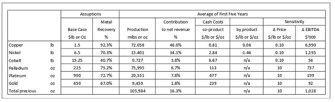
| Page | 22-3 | |
| 12/10/2012 |
| POLYMET MINING CORP. | |
| UPDATED TECHNICAL REPORT ON THE NORTHMET DEPOSIT | |
| MINNESOTA, USA |
The price assumptions included July 2006 average prices (shortly before publication of the DFS), the Base Case and the NI 43-101 case described previously. The table shows a sensitivity analysis of a ± 10% change in the Base Case metal price assumptions.
Table 22-3 sets out key financial statistics – the internal rate of return on the future capital investment and the present value of the future cash flow (including capital costs) using a 5% and 7.5% discount rate on both a pre-tax and an after-tax basis. The bottom section of the table shows the average over the first five years of full-scale production for gross revenue (before royalties and third-party processing fees), net revenues (after those costs) and EBITDA.
The price assumptions included July 2006 average prices (shortly before publication of the DFS), the Base Case and the NI 43-101 case described previously. The table shows a sensitivity analysis of a ± 10% change in the Base Case metal price assumptions.
| Table 22-3: | Economic Projections on a Range of Metal Price Assumptions |
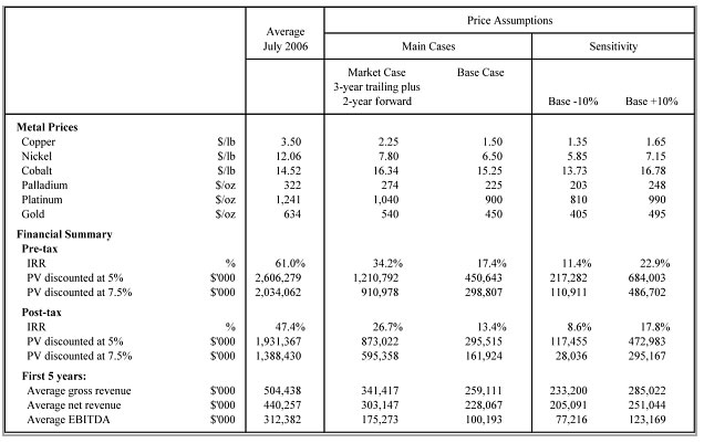
During the first five years of full-scale production, cash costs of production (excluding amortization of capital) on a co-product basis (allocating costs to each metal according to its contribution to revenue) and using Base Case metal price assumptions are projected at $0.81/lb for copper, $2.84/lb for nickel, and $113, $477, and $239 per ounce respectively for palladium, platinum, and gold.
| Page | 22-4 | |
| 12/10/2012 |
| POLYMET MINING CORP. | |
| UPDATED TECHNICAL REPORT ON THE NORTHMET DEPOSIT | |
| MINNESOTA, USA |
Alternatively, using the by-product method whereby revenues from other metals are offset against costs of a primary metal, the five-year average cash cost of copper would be $0.06/lb or, if NorthMet were viewed as a nickel mine, nickel costs would be minus $1.46/lb.
After state and federal taxes, the Base Case rate of return is 13.4% and the present value of the future cash flow discounted at 7.5% per annum is $162 million. During the first five years of full-scale operation, EBITDA (Earnings before Interest, Taxation, Depreciation, and Amortization, or operating cash flow) is projected to average $100 million a year.
A $0.10/lb change in the copper or nickel price would increase or decrease average annual EBITDA during the first five years of full-scale operation by $7.0 million and $1.2 million respectively and a $10/oz change in all of the precious metal prices (palladium, platinum, and gold) would increase or decrease the five-year average annual EBITDA by $1.0 million.
| 22.1.3 | 2008 DFS Update |
Capital Costs
Since the September 2006 DFS, and on a like-for-like basis, the total capital cost has increased by 36% to $516.8 million. This increase reflects both cost inflation and design scope changes since the DFS, including facilities needed to ship concentrate during the construction and commissioning of the new hydrometallurgical plant.
In addition, PolyMet anticipated $85.1 million of expenditures on measures to protect the environment, over and above the measures contemplated in the DFS. $76.6 million for mining equipment that was assumed to be provided by a mining contract in the DFS has been incorporated as an operating lease in updated operating costs.
PolyMet has previously stated that it has been reviewing the possibility of selling concentrate during the construction and commissioning of new metallurgical facilities. This staged approach shortens the initial construction period, makes the Project less sensitive to the delivery schedule for long lead-time equipment such as autoclave vessels, and means that PolyMet can commence operations of the mine, the existing crushing and milling plant, the existing tailings disposal facilities, and the new flotation circuit, before starting the new hydrometallurgical plant.
As a result of the staged approach, the total capital required prior to initial production and sales declines to $312.3 million, which includes $64.7 million of additional environmental safeguards for this level of activity (Table 22-4).
| Page | 22-5 | |
| 12/10/2012 |
| POLYMET MINING CORP. | |
| UPDATED TECHNICAL REPORT ON THE NORTHMET DEPOSIT | |
| MINNESOTA, USA |
Table 22-4: Capital Costs (US$ M)
| Change | Initial Concentrate | |||||||||
| Full Project | from DFS | Sales | ||||||||
| Definitive Feasibility Study | 379.8 | 138.7 | ||||||||
| Escalation and other scope changes | 137.0 | 36% | 108.9 | |||||||
| Total | 516.8 | 247.6 | ||||||||
| Environmental measures | 85.1 | 64.7 | ||||||||
| Total change | 222.1 | 58% | 173.6 | |||||||
| TOTAL | 601.9 | 312.3 | ||||||||
Operating Plans and Costs
The overall mining and operating plan remains the same as that defined in the DFS and which forms the basis of the plan being analyzed in the environmental impact statement. PolyMet intends to mine 32,000 tons of ore per day for an operating life of twenty years, processing a total of 224 million tons of ore.
The mine plan continues to be based on the following metal prices: copper - $1.25/lb, nickel - $5.60 per pound, cobalt - $15.25/lb, palladium - $210 per ounce, platinum - $800 per ounce, and gold - $400 per ounce.
Operating costs per ton of ore processed have increased to $13.33 from $11.02 in the DFS reflecting higher fuel, mine equipment, and other consumable costs, as well as general inflation. The cost of mining and delivering ore to the plant is now estimated at $4.31 per ton compared with $3.80 per ton in the DFS. The increase in mining costs has been partially offset by the lower strip ratio, larger mining equipment, and owner versus contractor operation.
The economic analysis is based on SEC-reserve standards, namely the three-year trailing average, which we calculated at April 30, 2008 (the end of our first fiscal quarter). This price deck is copper - $2.90/lb, nickel - $12.20/lb, cobalt - $23.50/lb, palladium - $320/oz, platinum - $1,230/oz, and gold - $635/oz. While these prices are somewhat higher than those used on the economic analysis in the DFS, each price is well below current market levels – in the first quarter of 2008, the following prices prevailed: copper - $3.52/lb, nickel - $13.09/lb, cobalt - $46.37/lb, palladium - $441/oz, platinum - $1,867/oz, and gold - $925/oz.
This translates into copper cash costs of $1.05 per pound using a co-product basis to calculate costs, compared with the DFS estimate of $0.81/lb. Taking revenues from the other metals as a deduction against costs, the co-product basis shows a cost of $(0.28) per pound compared with $0.06 per pound in the DFS.
| Page | 22-6 | |
| 12/10/2012 |
| POLYMET MINING CORP. | |
| UPDATED TECHNICAL REPORT ON THE NORTHMET DEPOSIT | |
| MINNESOTA, USA |
Economic Summary
Key economic metrics include earnings before interest, tax, depreciation, and amortization (EBITDA) which is projected to increase to $217.3 million on average over the first five years of operations from $175.3 million estimated in the DFS. The net present value of future cash flow (after tax) discounted at 7.5% is estimated to be $649.4 million compared with $595.4 million in the DFS, and the after tax internal rate of return is now estimated at 30.6% compared with 26.7% in the DFS. The table below also sets out the affect on EBITDA of a 10% change in each metal price.
| Table 22-5: | Key Economic Highlights |
![]()
| Page | 22-7 | |
| 12/10/2012 |
| POLYMET MINING CORP. | |
| UPDATED TECHNICAL REPORT ON THE NORTHMET DEPOSIT | |
| MINNESOTA, USA |
| Table 22-6: | Metal Prices |

| 22.2 | Comments on Section 22 |
PolyMet plans to complete a full update of both capital and operating costs when the detailed design is finanalized as a result of the environmental review and permitting process. | |
In addition to reflecting the scope and cost of this design, the update will also reflect current metal market conditions. |
| Page | 22-8 | |
| 12/10/2012 |
| POLYMET MINING CORP. | |
| UPDATED TECHNICAL REPORT ON THE NORTHMET DEPOSIT | |
| MINNESOTA, USA |
| 23 | ADJACENTPROPERTIES |
There are no adjacent properties that PolyMet is proposing to explore or drill as part of any drilling program or other evaluation. There are several other deposits in the Duluth Complex, including the Mesaba project owned by Teck Resources, Serpentine owned by Encampment Resources, and the Nokomis project owned by Twin Metals, a join venture between Duluth Metals and Antofagasta.
Twin Metals has retained Bechtel Corporation to conduct a prefeasibility study on the Nokomis project. Teck completed an internal prefeasibility study on Mesaba when it was seeking to acquire the Erie Plant.
| Page | 23-1 | |
| 12/10/2012 |
| POLYMET MINING CORP. | |
| UPDATED TECHNICAL REPORT ON THE NORTHMET DEPOSIT | |
| MINNESOTA, USA |
| 24 | OTHERRELEVANTDATA ANDINFORMATION |
| 24.1 | US Steel Assays (1960s and 1970s) |
US Steel assays are derived from old records which are incomplete in terms of QA/QC details. There are, however, less than ~200 US Steel assays remaining in the database that have not been replaced by more recent assays.
Gatehouse (2000a) summarizes the US Steel sampling and assaying:
USX ‘bx’ diameter drilling and 10 ft intervals (late60s-70s) was sampled using anvil splitting and prepared and analysed by the central USX laboratory. Sample rejects were kept as –6# and –20# material produced by gyratory and rolls crushers respectively. The precise techniques are not available but given the era, the style of analyses done at that time, and nature of the company it is highly probable that total copper and nickel assays were produced using AAS. No Au or PGMs were analysed. No quality control has been found for this work.
There are 1,790 ACME aqua regia re-assays of samples previously assayed by US Steel. Averages for US Steel and ACME, respectively are copper 0.39% and 0.39%; nickel 0.14% and 0.09% . Two-hundred and seventeen check assays by Chemex are available. Averages for US Steel and Acme, respectively, are copper 0.25% and 0.25%; nickel 0.11% and 0.08% .. Thus, US Steel copper assays match, on average, both those by ACME and Chemex. Nickel appears high in the US Steel assays, which may partly be a result of a more total digestion used. Acme’s acid digestion was weaker than that used by Chemex.
| 24.1.1 | Status of Nickel Assays |
Gatehouse (2000b) summarizes the status of the Ni assays: |
Against Genalysis ICP (4B), Chemex partial aqua regia assays are strongly biased as should be expected. On average, the Chemex preferred assays used for the resource calculation are biased low by 5-6% against Genalysis totals. The clear conditional bias in this data is also as expected and consistent with Lakefield metallurgical reports of a proportion of the nickel resident in silicates. Bias changes from about 20% at 500-600 ppm to no recognizable bias at greater than about 0.3% Ni. This pattern is consistent with higher proportions of Ni being resident in sulfide at higher grades. Lakefield metallurgical reports suggest that Ni in silicates is variable between 200 and 700 ppm. This is also consistent with Co results.
In summary, the NorthMet Ni resource is based on partial digest results. At worst, the average bias would be 5% lower than total results. This does not necessarily
| Page | 24-1 | |
| 12/10/2012 |
| POLYMET MINING CORP. | |
| UPDATED TECHNICAL REPORT ON THE NORTHMET DEPOSIT | |
| MINNESOTA, USA |
alter the economics of the Project as it may eventuate that Lakefield head assays on which recoveries have been predicated may prove themselves similarly biased.
| 24.1.2 | Status of Copper Assays |
Gatehouse (2000b) summarizes the status of the copper assays: |
On average, preferred Chemex aqua regia assays are biased low by about 2% against Lakefield XRF results (2A) , by 5% against Genalysis total acid digest ICP (2B) and by 1-2% against Chemex total digest ICP(2C). Such results are consistent with the low partitioning of Cu into silicates and represent a limit of a tolerable assay outcome. Biases of much greater than 5% are not acceptable and require improved assay.
Given the notionally total nature of Genalysis and Lakefield assays it is probable the Chemex aqua regia used in the resource data is low biased from an accurate result by less than 5% on average. This bias is conservative and would have no negative impact on resource figures.
| 24.1.3 | Status of Cobalt Assays |
Gatehouse (2000b) summarizes the status of the cobalt assays: |
The Chemex aqua regia digestions are significantly low biased, on average about 20%, against Genalysis total assays. The bias is conditional and significantly increases with lower grade. Though the number of samples is smaller, the same effect can be seen between Chemex aqua regia and Chemex total digest ICP.
Cobalt forms a very small portion of the value of the resource and, for economic purposes and factoring through metallurgical recoveries, its resource value is likely to be currently underestimated by around 20%. A small upside exists on the value of the resource by virtue of underestimated resource cobalt being related to total cobalt used in metallurgical calculations.
| 24.1.4 | Status of the Palladium Assays |
Gatehouse (2000b) summarizes the status of the palladium assays: |
On average, Chemex is biased about 2% high against both Genalysis and Lakefield. Bias is not conditional against Lakefield. Chemex bias is conditional against
Genalysis’ NiS assay and increases with grade. It is not considered significant given the nugget imprecision between assay types due to sub-sampling and signified by the large dispersion in the …scatter points. However, this situation should be monitored with ongoing quality control in the event that it might become significant with changing mineralized domain.
| Page | 24-2 | |
| 12/10/2012 |
| POLYMET MINING CORP. | |
| UPDATED TECHNICAL REPORT ON THE NORTHMET DEPOSIT | |
| MINNESOTA, USA |
| 24.1.5 | Status of the Platinum Assays |
Gatehouse (2000b) summarizes the status of the platinum assays: |
On average, Chemex is biased low against both Genalysis NiS assays(6B) and Lakefield lead oxide fire assays(6A). Further a conditional bias against Genalysis is similar to that of palladium and similar ongoing monitoring is recommended.
| 24.1.6 | Status of the Gold Assays |
Gatehouse (2000b) summarizes the status of the gold assays: |
As with Platinum, gold by virtue of its low abundance is subject to significant sub- sampling nugget effects. Though biases are apparent, the low contribution of Au to economic value means they are not significant at this time. However, quality control monitoring should be continued.
Against Becquerel NAA (7C), a very good reference technique for gold analyses, Chemex gold is biased low by 20%. The low levels (50 ppb) and severe nugget effects render this insignificant. On average, Chemex is biased low against both Genalysis NiS assays and Lakefield lead oxide fire assays. Further, a conditional bias against Genalysis is similar to that of palladium.
Extraction of Au into NiS during fire assay is inefficient. The low bias of Genalysis against Chemex (7B) is expected and not relevant.
The low bias of Lakefield against Chemex is largely a function of assay imprecision at very low grades and is not significant…
| 24.1.7 | Summary–Copper, Nickel, Cobalt |
Gatehouse (2000b) summarizes the status of the copper, nickel and cobalt assays: |
Chemex aqua regia assays, on which the Cu Ni Co resources are based, are biased low by a small amount. The total economic impact will be less than 5%, which is acceptable for resource assays. Never the less, it is highly probable that there remains an inherent bias.
Initial results for a limited number (54) of samples from the recent metallurgical drilling program support Gatehouse’s prediction. Cobalt and nickel assays from 4- acid digestions being 14% and 5%, respectively, higher than assays based on aqua regia. Copper values are similar.
A number of batches assayed in 2000 had included PolyMet standards (N1-3). Some of these have nickel assays that report approximately 10 to 20% above the recommended value though significantly more batches understate nickel. Copper values were largely accurate.
| Page | 24-3 | |
| 12/10/2012 |
| POLYMET MINING CORP. | |
| UPDATED TECHNICAL REPORT ON THE NORTHMET DEPOSIT | |
| MINNESOTA, USA |
| 24.1.8 | Summary–Platinum Group Elements and Gold |
Gatehouse (2000b) summarizes the status of the platinum group element and gold assays: |
Though some evidence for conditional biases exist between lead oxide and NiS fire assay for PGEs the low level is acceptable for lead oxide fire assay to be used for ongoing resource assessment. However, of lesser economic significance, the strong negative bias of gold in NiS analyses and its greater cost and expertise required for good assays, strongly mitigates against the NiS technique. However, NiS fire assay for PGEs should be used for quality control monitoring as an ongoing precaution against the potential for significant bias in different mineralized domains at NorthMet.
It is well recognized that nickel-sulphide (NiS) assays underestimate gold. The only good reason to select NiS assaying is for the determination of rhodium, rhenium, etc (Bloom, pers comm).
| Page | 24-4 | |
| 12/10/2012 |
| POLYMET MINING CORP. | |
| UPDATED TECHNICAL REPORT ON THE NORTHMET DEPOSIT | |
| MINNESOTA, USA |
| 25 | INTERPRETATION ANDCONCLUSIONS |
AGP estimated a mineral resource for the NorthMet Deposit using data supplied by PolyMet. This data incorporates the 2007 summer drilling results that were available as of October 15, 2007. The model used the same interpolation methodology used in the Wardrop September 2007 report.
The pre-2007 dataset used by Wardrop was extensively verified by previous authors and the QP spot checked selected holes from the US Steel era and the PolyMet 1999, 2000 and 2005 drill campaign against the paper copies of the laboratory certificates. The 2007 drilling was verified by AGP using the electronic version of the laboratory certificate.
Model was interpolated using Ordinary Kriging with Inverse Distance Squared and Nearest Neighbour interpolation methods used for validation. No significant discrepancies exist between these methods.
Based on the review of the QA/QC, Data validation and statistical analysis of the data, AGP draws the following conclusions:
AGP has reviewed the methods and procedures to collect and compile geological and assaying information for the NorthMet Deposit and found them meeting accepted industry standards and suitable for the style of mineralization found on the property.
A mix of data type was use to generate the resource on the property including historical drill results drilled by US Steel data. Fourteen percent (14%) of the assayed footage is by Reverse Circulation (six inch) drilling; with the remainder by diamond coring was use in the resource estimate. PolyMet validated the RC drill results against twin (or near twin) drill hole and found them to be satisfactory. AGP’s
Principal Resource Geologist visited the site, reviewed some of the historical drill core and interviewed PolyMet staff. AGP believes that the information supplied for the resource estimate and used in this report is accurate.A QA/QC program comprising industry standard blank, standard and duplicate samples has been used on the Project since the 2005 drill program. QA/QC submission rates meet industry-accepted standards.
Data verification was performed by AGP through site visits, collection of independent character samples and a database audit prior to mineral resource estimation. AGP found the database to be exceptionally well maintained and error free and usable in mineral resource estimation. AGP also believes that the information supplied for the resource estimate and used in this report is accurate.
| Page | 25-1 | |
| 12/10/2012 |
| POLYMET MINING CORP. | |
| UPDATED TECHNICAL REPORT ON THE NORTHMET DEPOSIT | |
| MINNESOTA, USA |
The specific gravity determinations are representative of the in-situ bulk density of the rock types. | ||
Sampling and analysis programs using standard practices provided acceptable results. AGP believes that the resulting data can effectively be used in the estimation of resources. | ||
Core handling, core storage and chain of custody are consistent with industry standards. | ||
In AGP’s opinion the current drill hole database is adequate for interpolating grade models for use in resource estimation. | ||
Mineral resources were classified using logic consistent with the CIM definitions referred to in NI 43-101. | ||
AGP estimate the NorthMet resources (above a US$7.42 NMV cut-off) to contain 694.2 million short tons (629.8 million tonnes) in the Measured and Indicated categories grading at 0.265% copper, 0.077% nickel, 68 parts per billion (ppb) platinum, 239 ppb palladium, 35 ppb gold and 71 parts per million (ppm) cobalt. The Inferred category (above a US$7.42 NMV cut-off) totals 229.7 million short tons (208.4 million tonnes) grading at 0.273% copper, 0.079% nickel, 73 ppb platinum, 263 ppb palladium, 37 ppb gold and 56 ppm cobalt. | ||
The NMV formula used and described in Section 17.2.12 of this report includes gross metal price multiplied by the processing recovery minus refining, insurance and transportation charges and is the same formula used in the Hunter 2006 report. | ||
Above the 0.2% copper cut-off the NorthMet Deposit contains 442.1 million short tons (401.0 million tonnes) in the Measured and Indicated categories grading at 0.325% copper, 0.089% nickel, 81 ppb platinum, 292 ppb palladium, 41 ppb gold and 73 ppm cobalt. The Inferred category totals 158.7 million short tons (144.0 million tonnes) grading at 0.329% copper, 0.088% nickel, 86 ppb platinum, 315 ppb palladium, 43 ppb gold and 55 ppm cobalt. | ||
Comparing the AGP model with the previously published estimate, Table 17.23 of the Wardrop, September 2007 report, results show an increase of 15.5 million short tons (14.1 million tonnes) in the Measured category and 40.5 million short tons (36.7 million tonnes) in the Indicated category for a total of 56 million short tons (50.8 million tonnes) or 8.1% increase in the Measured plus Indicated category. The Inferred Resource tonnage dropped by 21.9 million short tons (26.4 million tonnes) or 9.5%. The comparison includes resources above a US$7.42 Net Metal Value (NMV) cut-off from surface down to the 0.00 ft elevation level. | ||
Compared with the Wardrop September 2007 estimate, grades in the Measured and Indicated categories dropped slightly for copper and nickel and increased slightly for platinum, palladium, gold and cobalt grade elements. Copper changed by -0.3%, nickel by -0.5%, platinum by +2.1%, palladium by +1.8%, gold by +2.1% and cobalt by +0.1%. However, the contained metal value increased for all elements by about 10% in the Measured and Indicated categories. Copper increased by 8.5%, nickel by 8.2%, platinum by 11.1%, palladium by 10.8%, gold by 11.0% and cobalt by 8.9%. |
| Page | 25-2 | |
| 12/10/2012 |
| POLYMET MINING CORP. | |
| UPDATED TECHNICAL REPORT ON THE NORTHMET DEPOSIT | |
| MINNESOTA, USA |
The work carried out during the Summer 2007 drill program has met the primary objectives relating to the in-fill drilling.
Reserves for the Northmet project contained within the DFS pit shell amounted to:
Proven = 118.1 million tons Grading 0.30% copper, 0.09% nickel, 75 ppb platinum, 275 ppb palladium, 38 ppb gold and 75 ppm cobalt.
Probable = 156.5 million tons Grading 0.27% copper, 0.08% nickel, 75 ppb platinum, 248 ppb palladium, 37 ppb gold and 72 ppm cobalt.
Total Proven and Probable = 274.7 million tons Grading 0.28% copper, 0.08% nickel, 75 ppb platinum, 260 ppb palladium, 37 ppb gold and 73 ppm cobalt.
Further increases in reserves are dependent upon the conditions outlined in the ongoing environmental review and permitting process.
| Page | 25-3 | |
| 12/10/2012 |
| POLYMET MINING CORP. | |
| UPDATED TECHNICAL REPORT ON THE NORTHMET DEPOSIT | |
| MINNESOTA, USA |
| 26 | RECOMMENDATIONS |
AGP offers the following recommendations:
PolyMet should proceed with final design engineering and construction of the NorthMet Project as soon as permitting allows. Prior to construction, PolyMet should:
Review and update the scope of the Project design to reflect any changes resulting from the environmental review process and other project enhancements update the capital and operating cost estimates based on the scope review and current prices
Prior to detailed, pre-production planning a limited program of close spaced drilling is recommended. This program will have two objectives:
To determine the optimum drill hole spacing for grade control and scheduling and,
To acquire sufficient data to increase confidence in grade affecting the initial open pit production.
Budget for 625 large diameter (5 1/2") reverse circulation drill holes averaging 30 ft for a total of 19,050 ft is estimated at $40 /ft for an all in cost of $782,000 including a $20,000 mobilization charge. Cost is less if using a 3 1/2 " diameter.
All of these items are in PolyMet's budgets for activities before the start of construction, for a total of $3.0 million.
Various recommendations for further work resulted from this Updated DFS, which have subsequently been completed. These included:
1) Various recommendations for further work resulted from the Updated DFS. Some of this work has been completed as of October 2012.
| 1) | Development of a low-grade recovery relationship for copper and nickel and the other metals | |
Development of a low-grade recovery relationship for copper, nickel and the other metals needs to be completed on low grade samples using a consistent metallurgical protocol. As the cutoff grade is dropped, the impact of lower grades becomes greater and also its impact on overall project economics. | ||
| 2) | Updating of metal payment pricing and terms | |
Metal prices and terms for mining planning purposes have not been updated since the DFS. With the introduction of concentrate sales, long-term marketing with |
| Page | 26-1 | |
| 12/10/2012 |
| POLYMET MINING CORP. | |
| UPDATED TECHNICAL REPORT ON THE NORTHMET DEPOSIT | |
| MINNESOTA, USA |
Glencore, and changes to metal markets, the current cut-off is likely to exclude mineralization that would be economic to mine and process. | ||
| 3) | Stockpiling options possible to increase initial mill feed grade | |
Current low grade ore stockpile limit is for 5 million tons of material. If the limit is increased to a higher value, the initial years mill feed grade can be increased improving overall project economics. | ||
| 4) | Potential for daily mine ore production increase | |
The NorthMet resource base and the geometry of the deposits could allow for an increase in ore tonnage. |
| Page | 26-2 | |
| 12/10/2012 |
| POLYMET MINING CORP. | |
| UPDATED TECHNICAL REPORT ON THE NORTHMET DEPOSIT | |
| MINNESOTA, USA |
| 27 | CERTIFICATES OFQUALIFIEDPERSONS |
| 27.1 | Pierre Desautels, P.Geo. |
I, Joseph Rosaire Pierre Desautels, P.Geo, of Barrie, Ontario, do hereby certify that as one of the qualified person (QP) of this Technical Report, Updated Technical Report on the NorthMet Deposit dated 12 October 2012; and hereby make the following statements:
I am a Principal Geologist with AGP Mining Consultants Inc., with a business address at 92 Caplan Avenue, Suite 246, Barrie, Ontario, L4N 0Z7.
I am a graduate of Ottawa University (B.Sc. Hons., 1978).
I am a member in good standing of the Association of Professional Geoscientists of Ontario, Registration #1362.
I have practiced my profession in the mining industry continuously since graduation.
I have read the definition of “qualified person” set out in National Instrument 43-101 (NI 43-101) and certify that, by reason of my education, affiliation with a professional association (as defined in NI 43-101) and past relevant work experience, I fulfill the requirements to be a “qualified person” for the purpose of NI 43-101.
My relevant experience with respect to resource modeling includes 30 years’ experience in the mining sector covering database, mine geology, grade control, and resource modeling. I was involved in numerous projects around the world in both base metals and precious metals deposits.
I visited the Project site from March 21st to March 23rd, 2007, and again from August 27th to August 29th, 2007, for a period of six days in total.
I am responsible for the geology and resource portion of section 1, the complete section 2 and 3, section 4 with exceptions made for portion of the text that are outside my area of expertise and where I relied on the opinion of other experts as stated in section 3 of this report, the complete section 5 to 12, section 14, 23, 24 and a portion of section 25 and 26 of the technical report titled Updated Technical Report on the NorthMet Deposit.
As of the date of this Certificate, to my knowledge, information, and belief, this technical report contains all scientific and technical information that is required to be disclosed to make the technical report not misleading.
I am independent of the Issuer (PolyMet Mining Inc. (PolyMet)) as defined by Section 1.5 of the Instrument.
I have read NI 43-101 and the Technical Report has been prepared in compliance with NI 43-101 and Form 43-101F1.
Signed and dated this 29th day of October 2012, at Barrie, Ontario.
| “Original Signed and Sealed” | ||
| Pierre Desautels, P.Geo. |
| Page | 27-1 | |
| 12/10/2012 |
| POLYMET MINING CORP. | |
| UPDATED TECHNICAL REPORT ON THE NORTHMET DEPOSIT | |
| MINNESOTA, USA |
| 27.2 | Gordon Zurowski, P.Eng. |
I, Gordon Zurowski, P.Eng, of Stoufville, Ontario, do hereby certify that as one of the qualified person (QP) of this Technical Report, Updated Technical Report on the NorthMet Deposit dated 12 October 2012; and hereby make the following statements:
I am a Principal Mine Engineer with AGP Mining Consultants Inc., with a business address at 92 Caplan Avenue, Suite 246, Barrie, Ontario, L4N 0Z7.
I am a graduate of the University of Saskatchewan, B.Sc. Geological Engineering 1989.
I am a member in good standing of the Association of Professional Engineers of Ontario, Registration #100077750.
I have practiced my profession in the mining industry continuously since graduation.
I have read the definition of “qualified person” set out in National Instrument 43-101 (NI 43-101) and certify that, by reason of my education, affiliation with a professional association (as defined in NI 43-101) and past relevant work experience, I fulfill the requirements to be a “qualified person” for the purpose of NI 43-101.
My relevant experience includes the design and evaluation of open pit mines for the last 24 years.
I visited the Project site from October 9 to October 11th, 2007 for a period of three days in total.
I am responsible for the mining portion of Section 1.4, the complete section 15 and 16 and a portion of section 26 of the technical report titled “Updated Technical Report on the NorthMet Deposit.”
As of the date of this Certificate, to my knowledge, information, and belief, this technical report contains all scientific and technical information that is required to be disclosed to make the technical report not misleading.
I am independent of the Issuer PolyMet Mining Inc. (PolyMet) as defined by Section 1.5 of the Instrument.
I have read NI 43-101 and the Technical Report has been prepared in compliance with NI 43-101 and Form 43-101F1.
Signed and dated 29thday of October 2012, at Stoufville, Ontario.
| “Original Signed and Sealed” | ||
| Gordon Zurowski, P.Eng. |
| Page | 27-2 | |
| 12/10/2012 |
| POLYMET MINING CORP. | |
| UPDATED TECHNICAL REPORT ON THE NORTHMET DEPOSIT | |
| MINNESOTA, USA |
| 27.3 | David Dreisinger, Ph.D., P. Eng., F.C.I.M., F.C.A.E. |
I, David Dreisinger, Ph.D., P.Eng., F.C.I.M., F.C.A.E. of Delta, British Columbia, do hereby certify that as one of the qualified person (QP) of this Technical Report, Updated Technical Report on the NorthMet Deposit, dated 12 October 2012; and hereby make the following statements:
I am the President of Dreisinger Consulting Inc. with a business address at 5233 Bentley Crescent, Delta British Columbia.
I am a graduate of Queen’s University of Kingston, Canada, B.Sc. Metallurgical Engineering 1980 and Ph.D. Metallurgical Engineering, 1984.
I am a Fellow of the Canadian Academy of Engineering and am a member in good standing of the Association of Professional Engineers and Geoscientists of British Columbia (Registration Number 15803).
I have practiced my profession continuously since graduation.
I have read the definition of “qualified person” set out in National Instrument 43-101 (NI 43-101) and certify that, by reason of my education, affiliation with a professional association (as defined in NI 43-101) and past relevant work experience, I fulfill the requirements to be a “qualified person” for the purpose of NI 43-101.
My relevant experience includes being employed in research and teaching at the University of British Columbia since 1984, currently holding the title of Professor and Chairholder, Industrial Research Chair in Hydrometallurgy in the Department of Materials Engineering. I have provided consulting services to the global metallurgical industry since 1987.
I visited the Project site on numerous occasions starting in January, 2004. Additionally, I have made visits to the SGS Minerals Laboratory in Lakefield, Canada to observe metallurgical testing of the Project ore since 2004.
I am responsible for the mineral processing portion of Section 1, and the complete section 13 and 17 of the technical report titled “Updated Technical Report on the NorthMet Deposit.”
As of the date of this Certificate, to my knowledge, information, and belief, this technical report contains all scientific and technical information that is required to be disclosed to make the technical report not misleading.
I am not independent of the Issuer PolyMet Mining Inc. (PolyMet) as defined by Section 1.5 of the Instrument. I currently serve as a director of PolyMet Mining Inc.
I have read NI 43-101 and the Technical Report has been prepared in compliance with NI 43-101 and Form 43-101F1.
Signed and dated 25thday of October 2012, at Lima, Peru.
| “Original Signed and Sealed” | ||
| David Dreisinger, Ph.D., P.Eng. |
| Page | 27-3 | |
| 12/10/2012 |
| POLYMET MINING CORP. | |
| UPDATED TECHNICAL REPORT ON THE NORTHMET DEPOSIT | |
| MINNESOTA, USA |
| 27.4 | William Murray, P.Eng. |
I, William Murray, P.Eng, of Richmond, British Columbia, do hereby certify that as one of the qualified person (QP) of this Technical Report, Updated Technical Report on the NorthMet Deposit dated 12 October 2012; and hereby make the following statements:
I am President of Optimum Project Services Ltd. with a business address at 6640 Gibbons Dr., Richmond, British Columbia.
I am a graduate of the Strathclyde University of Glasgow, Scotland, B.Sc. Electrical Engineering 1971.
I am a registered Professional Engineer in the Province of British Columbia and a member in good standing of the Chartered Engineers of the United Kingdom.
I have practiced my profession in the mining industry continuously since graduation.
I have read the definition of “qualified person” set out in National Instrument 43-101 (NI 43-101) and certify that, by reason of my education, affiliation with a professional association (as defined in NI 43-101) and past relevant work experience, I fulfill the requirements to be a “qualified person” for the purpose of NI 43-101.
My relevant experience includes a 40 year career with involvement at progressive stages of seniority in the evaluation and building of projects around the world in coal, iron, base metals and gold. My initial jobs with Anglo American of South Africa allowed exposure to all aspects of mine development including resource estimates; mine planning; process development; design engineering; and cost estimates. My work in recent years has also included economic valuations and market related aspects of mine development.
I visited the Project site in the fall of 2003 and have been to site numerous times and deeply involved in its development ever since.
I am responsible for the broad project description and execution plan; specific land deals, market and off-take; capital and operating costs and economic analyses as described in sections 1, 4, 18, 19, 20, 21 and section 22 of the technical report titled “Updated Technical Report on the NorthMet Deposit.”
As of the date of this Certificate, to my knowledge, information, and belief, this technical report contains all scientific and technical information that is required to be disclosed to make the technical report not misleading.
I am not independent of the Issuer PolyMet Mining Inc. (PolyMet) as defined by Section 1.5 of the Instrument.
I have read NI 43-101 and the Technical Report has been prepared in compliance with NI 43-101 and Form 43-101F1.
Signed and dated 25th day of October 2012, at Richmond, British Columbia.
| “Original Signed and Sealed” | ||
| William Murray, P.Eng. |
| Page | 27-4 | |
| 12/10/2012 |
| POLYMET MINING CORP. | |
| UPDATED TECHNICAL REPORT ON THE NORTHMET DEPOSIT | |
| MINNESOTA, USA |
APPENDIXA
LIST OFHOLESINCLUDED
| Appendix | A | |
| 12/10/2012 |


![]()


| POLYMET MINING CORP. | |
| UPDATED TECHNICAL REPORT ON THE NORTHMET DEPOSIT | |
| MINNESOTA, USA |
APPENDIXB
RAWASSAYSTATISTICS
| Appendix | B | |
| 12/10/2012 |

![]()


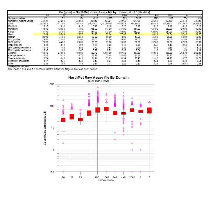


![]()
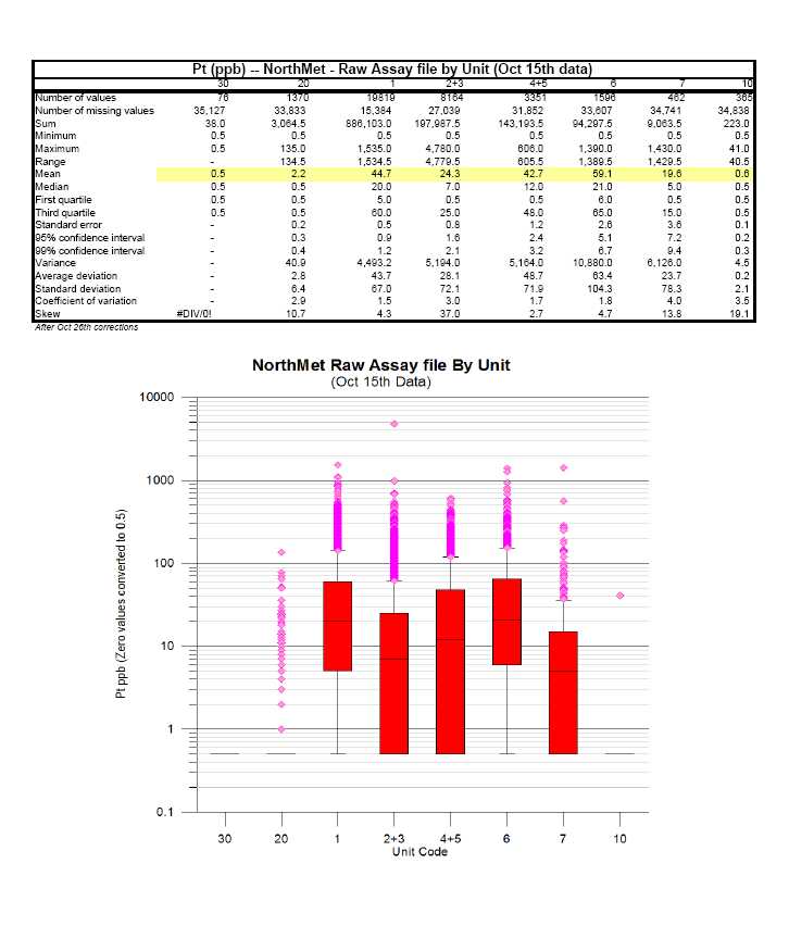
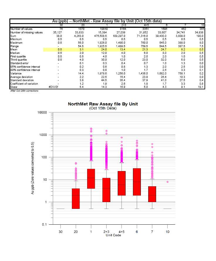


![]()


![]()
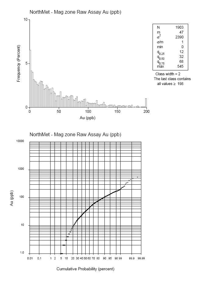


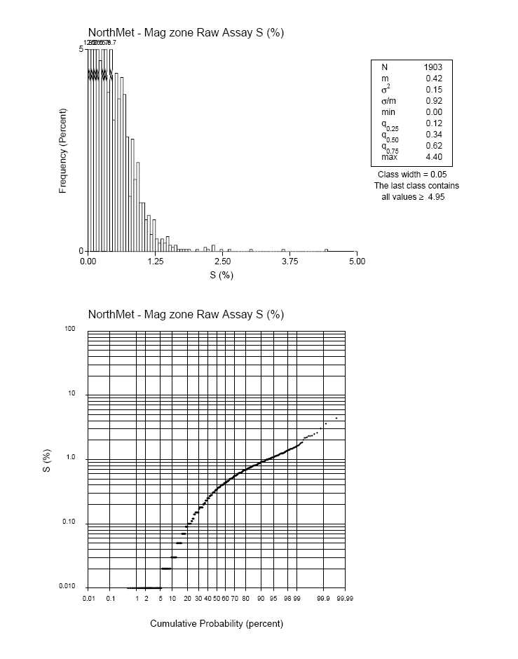

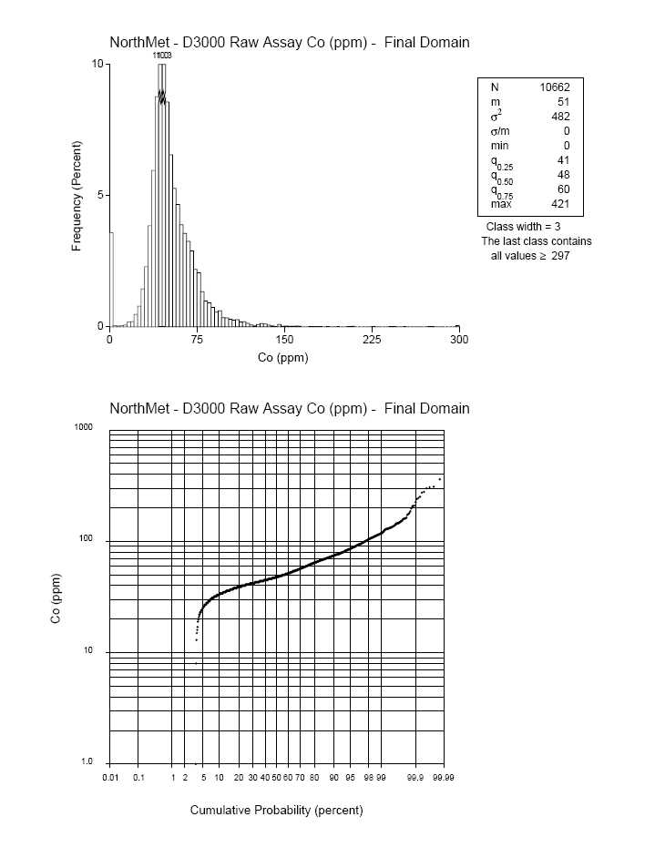
![]()


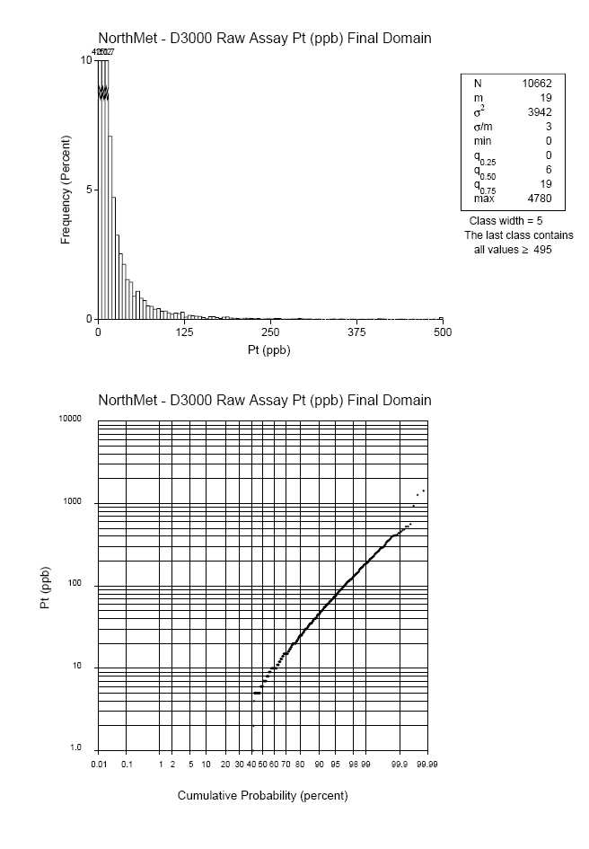


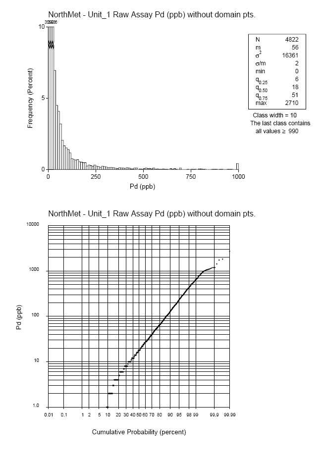
![]()


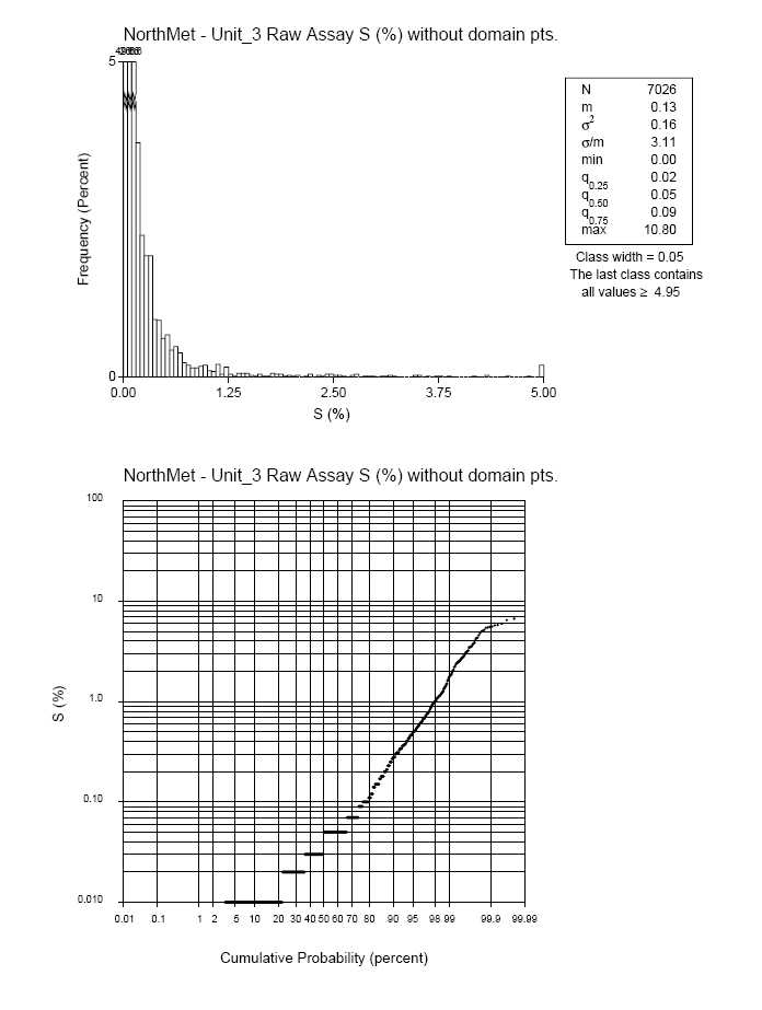

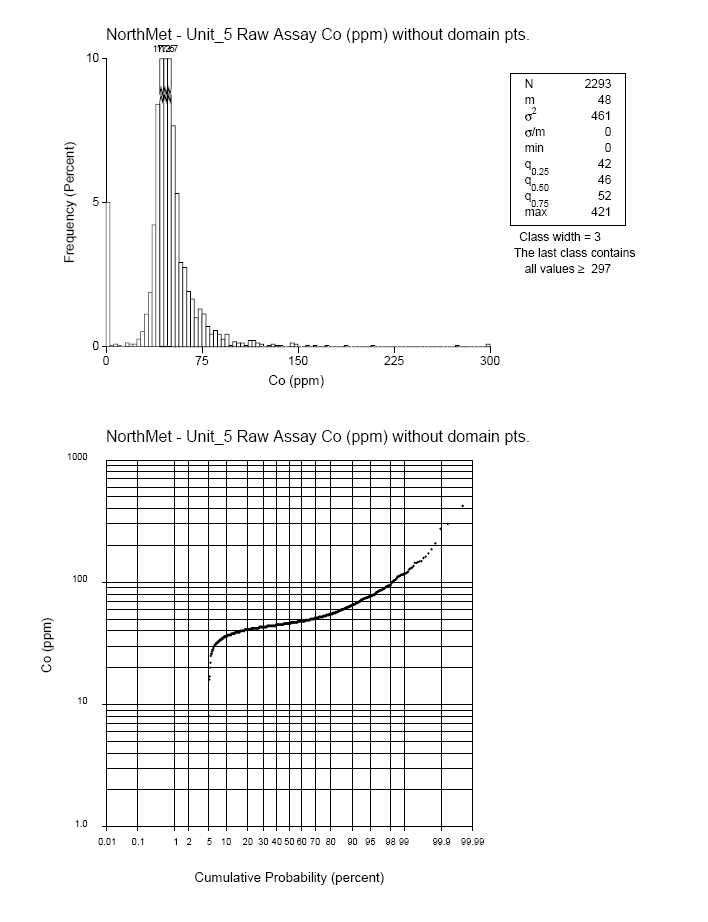
![]()
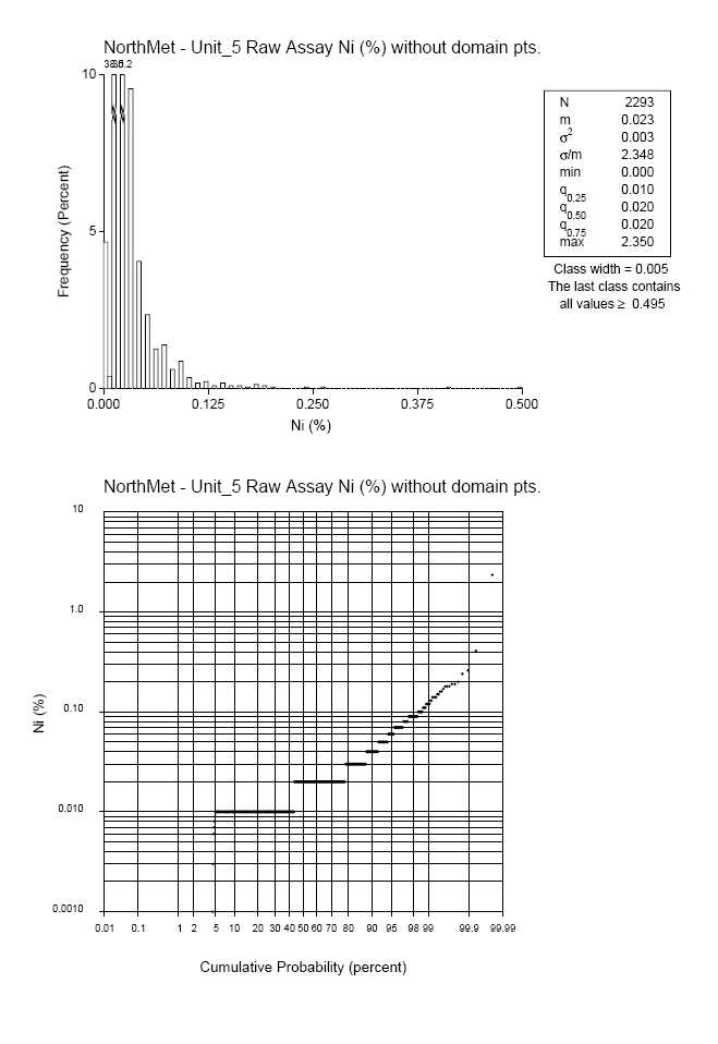


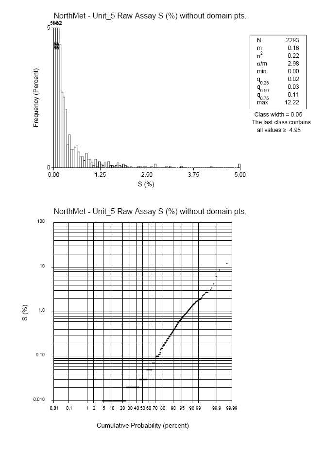


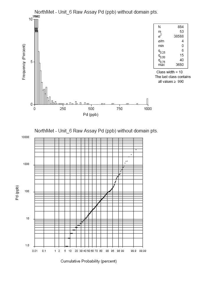
![]()


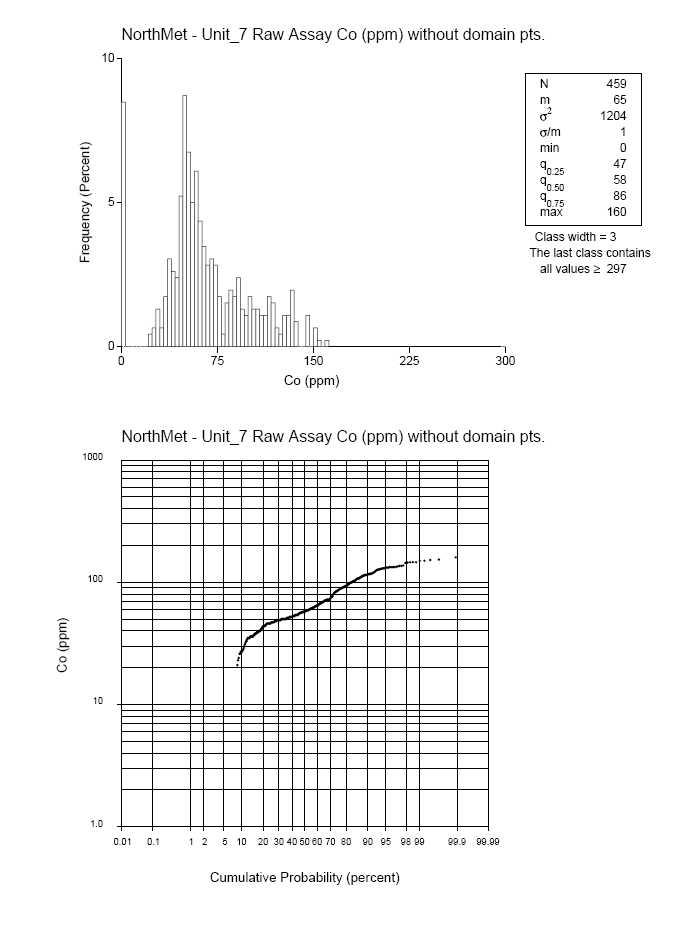

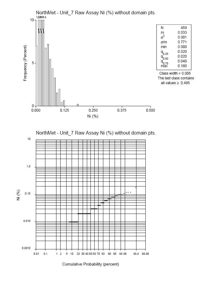


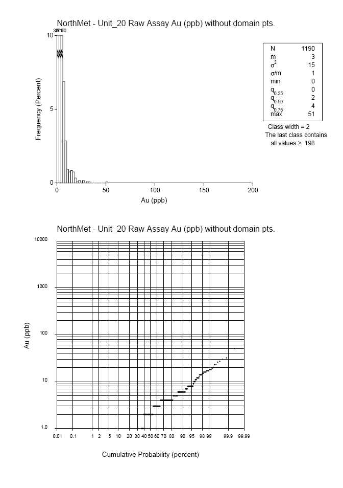
![]()


![]()


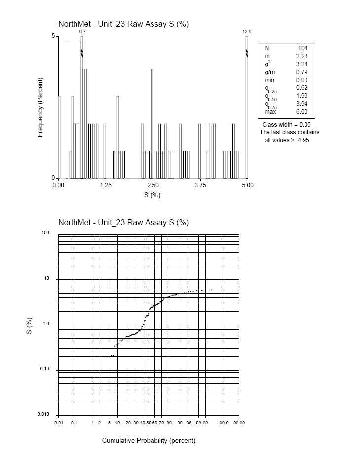

![]()


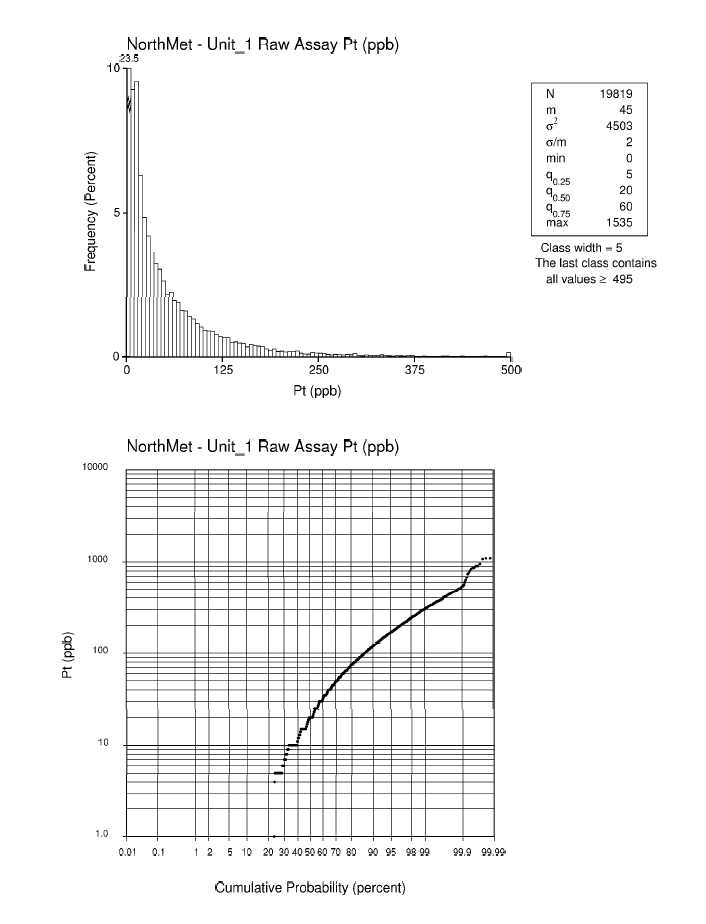
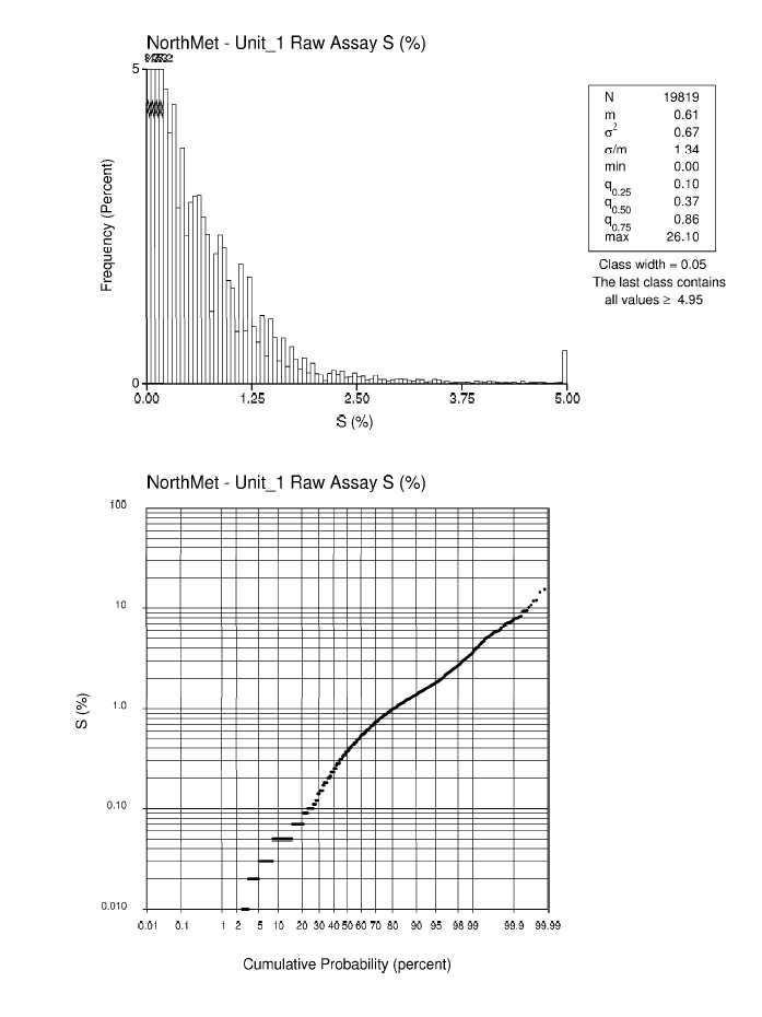


![]()


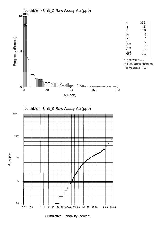

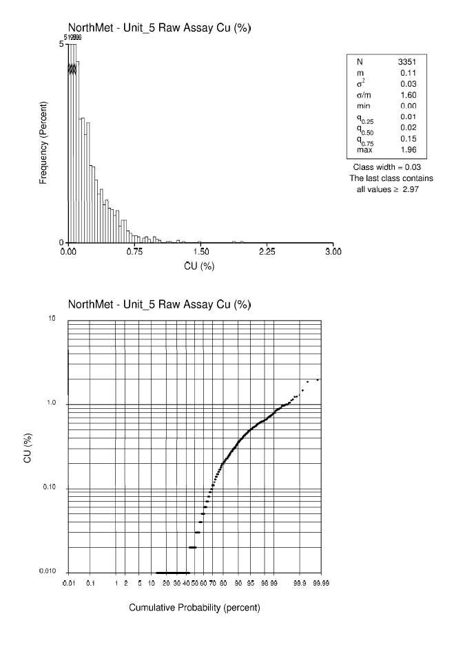


![]()
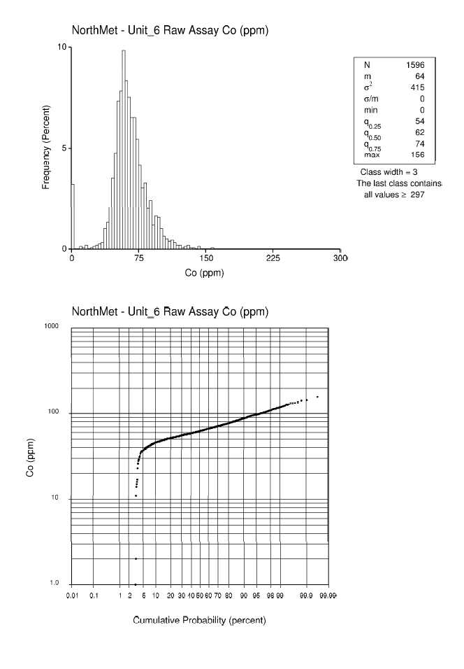


![]()
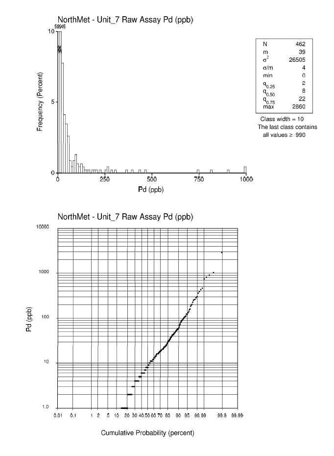


![]()
| POLYMET MINING CORP. | |
| UPDATED TECHNICAL REPORT ON THE NORTHMET DEPOSIT | |
| MINNESOTA, USA |
APPENDIXC
CAPPINGANALYSIS
| Appendix | C | |
| 12/10/2012 |
The decile analysis performed by Wardrop for the September 2007 resource model was not updated with the October 2007 dataset as very few additional data points were added. Results of the decile analysis and grade capping studies uses the May 25th 2007 dataset and plots generated from the study were reproduced here for readability.

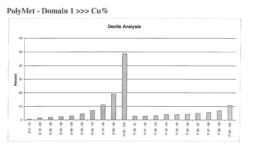
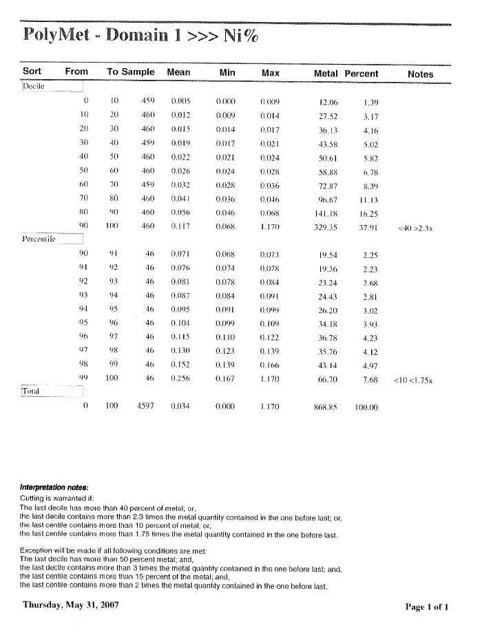


![]()


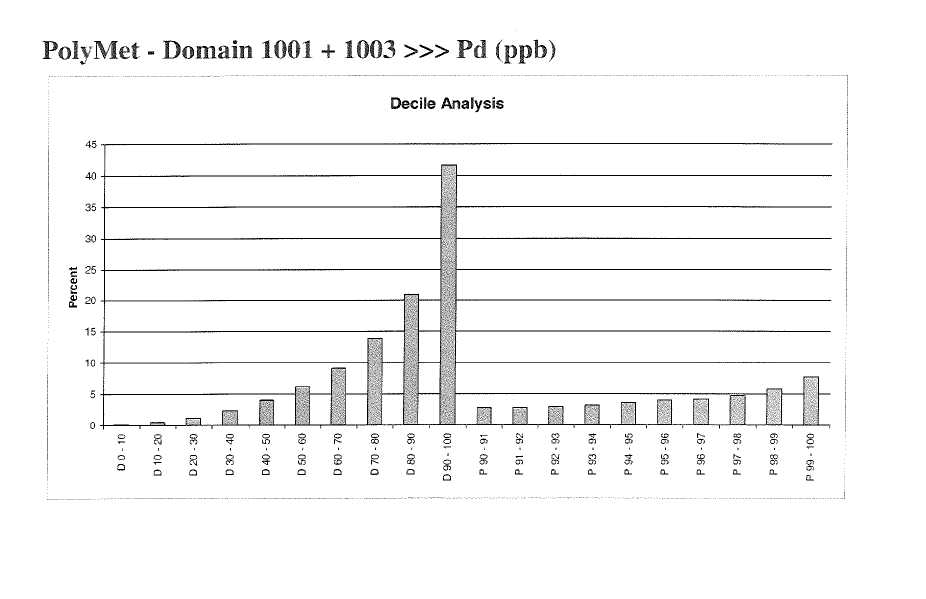

![]()
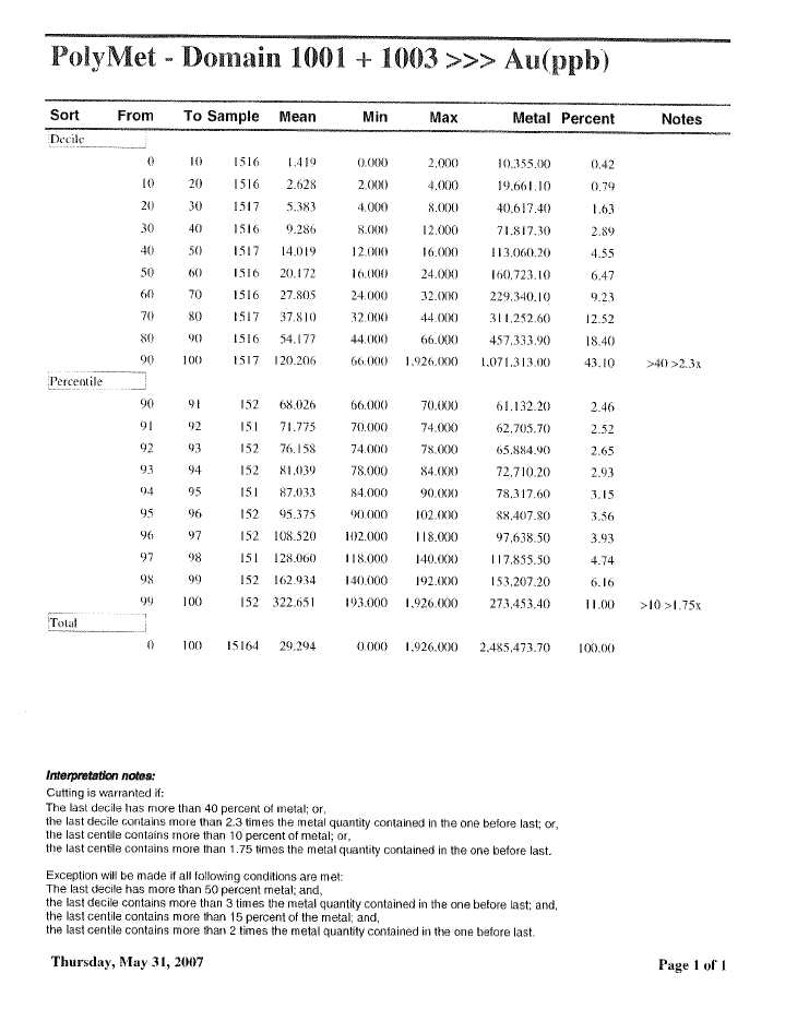


![]()


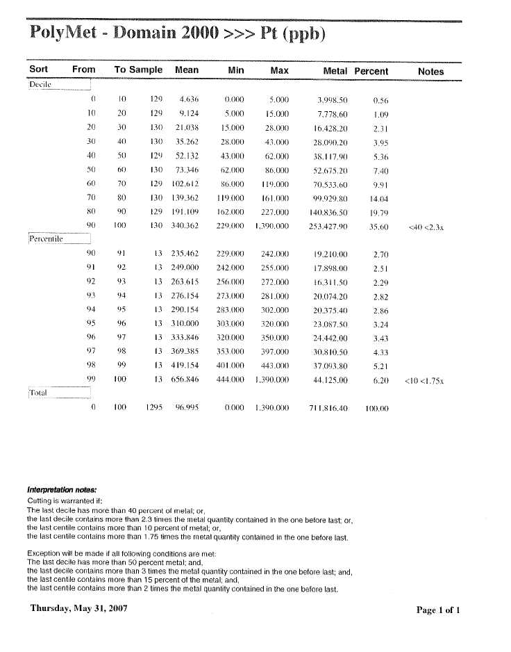
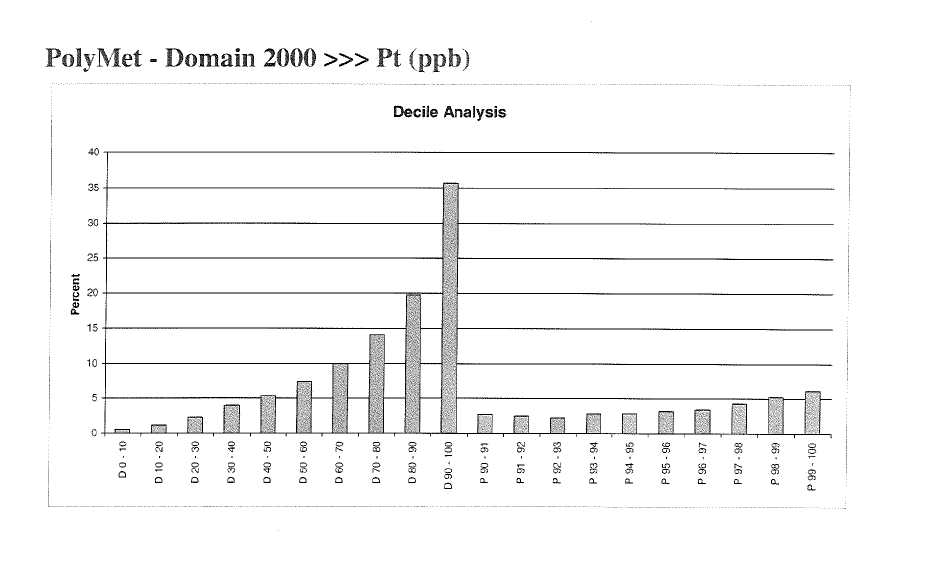

![]()


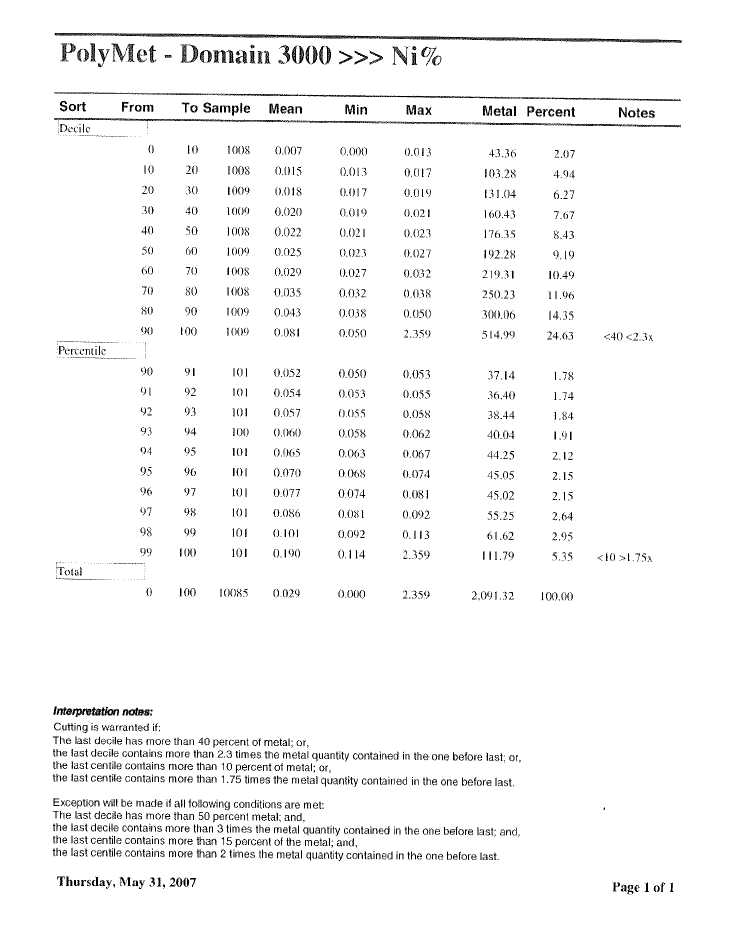


![]()


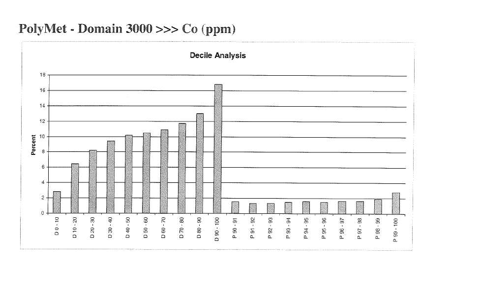

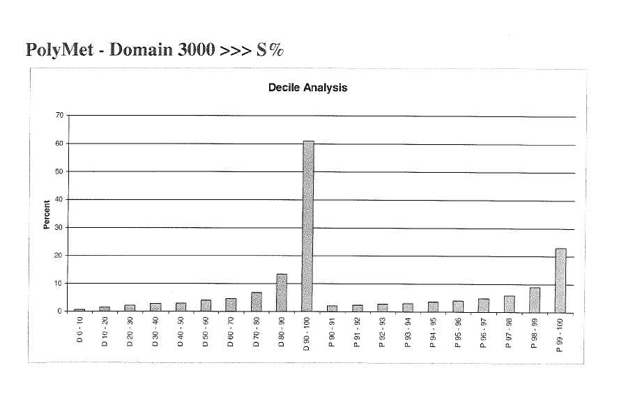

![]()


![]()
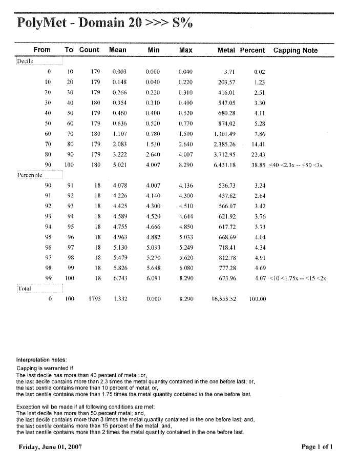


| POLYMET MINING CORP. | |
| UPDATED TECHNICAL REPORT ON THE NORTHMET DEPOSIT | |
| MINNESOTA, USA |
APPENDIXD
CORELENGTHSTATISTICS
| Appendix | D | |
| 12/10/2012 |


| POLYMET MINING CORP. | |
| UPDATED TECHNICAL REPORT ON THE NORTHMET DEPOSIT | |
| MINNESOTA, USA |
APPENDIXE
COMPOSITESTATISTICS
| Appendix | E | |
| 12/10/2012 |

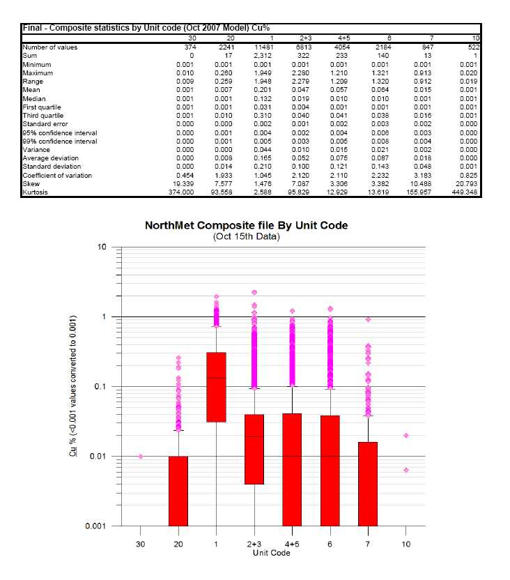
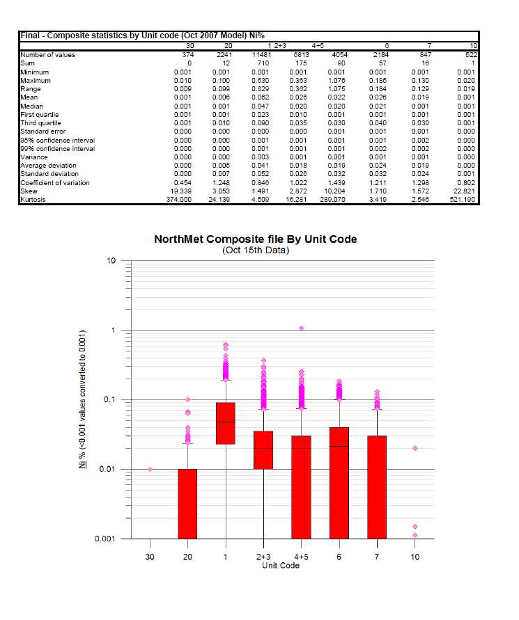


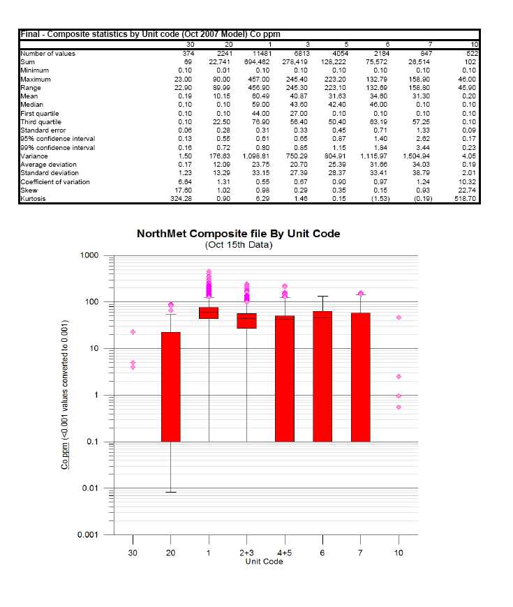


![]()


| POLYMET MINING CORP. | |
| UPDATED TECHNICAL REPORT ON THE NORTHMET DEPOSIT | |
| MINNESOTA, USA |
APPENDIXF
VARIOGRAPHY
| Appendix | F | |
| 12/10/2012 |
Downhole 1001 - Au
User Defined Rotation Conventions
| Nugget ==> 0.036 | |||||
| C1 ==> 0.748 | |||||
| C2 ==> 0.216 | |||||
| First Structure -- Exponential with Practical Range | |||||
| RH Rotation about the Z axis ==> -49 | |||||
| RH Rotation about the Y’ axis ==> -72 | |||||
| RH Rotation about the Z’ axis ==> 45 | |||||
| Range along the Z’ axis ==> 10.2 | Azimuth ==> 319 Dip ==> 18 | ||||
| Range along the Y’ axis ==> 182.4 | Azimuth ==> 32 Dip ==> -43 | ||||
| Range along the X’ axis ==> 42.9 | Azimuth ==> 66 Dip ==> 42 | ||||
| Second Structure -- Exponential with Practical Range | |||||
| RH Rotation about the Z axis ==> -68 | |||||
| RH Rotation about the Y’ axis ==> -53 | |||||
| RH Rotation about the Z’ axis ==> 11 | |||||
| Range along the Z’ axis ==> 1682.3 | Azimuth ==> 338 Dip ==> 37 | ||||
| Range along the Y’ axis ==> 1398.4 | Azimuth ==> 61 Dip ==> -9 | ||||
| Range along the X’ axis ==> 326.0 | Azimuth ==> 139 Dip ==> 52 | ||||
| Modeling Criteria | |||||
| Minimum number pairs req’d ==> 800 | |||||
| Sample variogram points weighted by # pairs | |||||
![]()
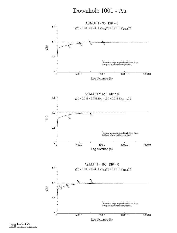


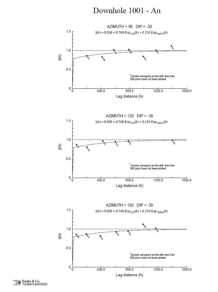

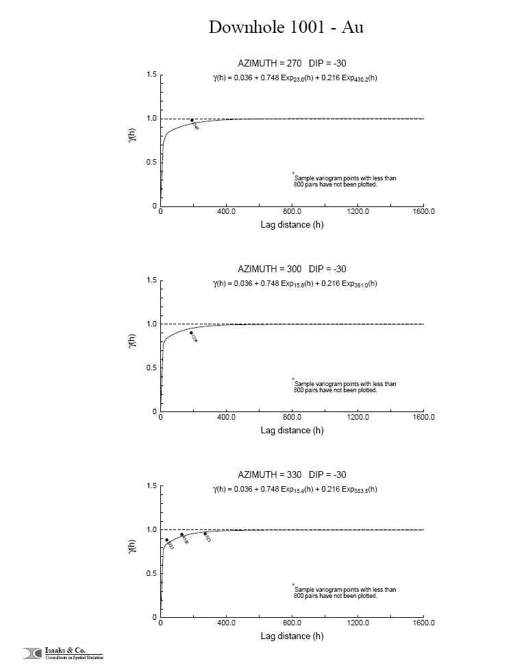

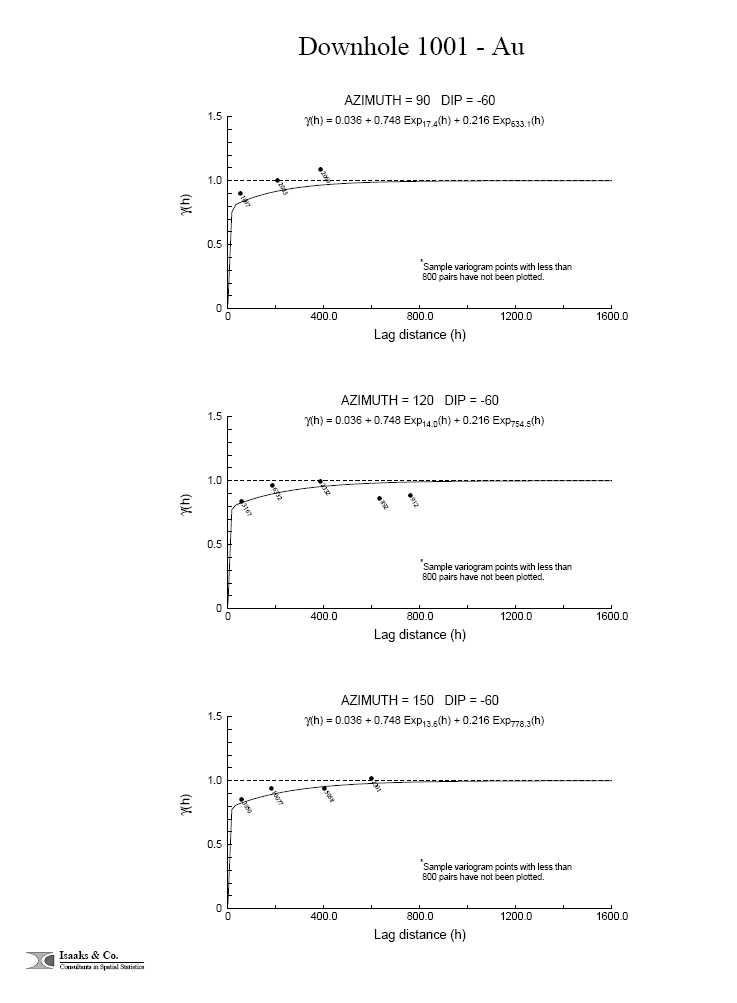
![]()
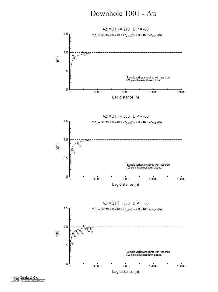

Downhole 1001 - Co
User Defined Rotation Conventions
| Nugget ==> 0.044 | |||
| C1 ==> 0.697 | |||
| C2 ==> 0.259 | |||
| First Structure -- Exponential with Practical Range | |||
| RH Rotation about the Z axis ==> -66 | |||
| RH Rotation about the Y’ axis ==> 58 | |||
| RH Rotation about the Z’ axis ==> 4 | |||
| Range along the Z’ axis ==> 72.1 | Azimuth ==> 156 Dip ==> 32 | ||
| Range along the Y’ axis ==> 663.4 | Azimuth ==> 64 Dip ==> 3 | ||
| Range along the X’ axis ==> 317.8 | Azimuth ==> 149 Dip ==> -58 | ||
| Second Structure -- Exponential with Practical Range | |||
| RH Rotation about the Z axis ==> -102 | |||
| RH Rotation about the Y’ axis ==> 23 | |||
| RH Rotation about the Z’ axis ==> 93 | |||
| Range along the Z’ axis ==> 2319.5 | Azimuth ==> 192 Dip ==> 67 | ||
| Range along the Y’ axis ==> 1860.7 | Azimuth ==> 9 Dip ==> 23 | ||
| Range along the X’ axis ==> 54.1 | Azimuth ==> 99 Dip ==> 1 | ||
| Modeling Criteria | |||
| Minimum number pairs req’d ==> 800 | |||
| Sample variogram points weighted by # pairs | |||
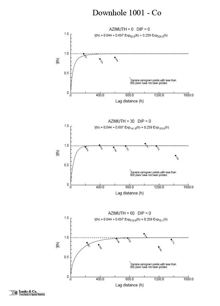
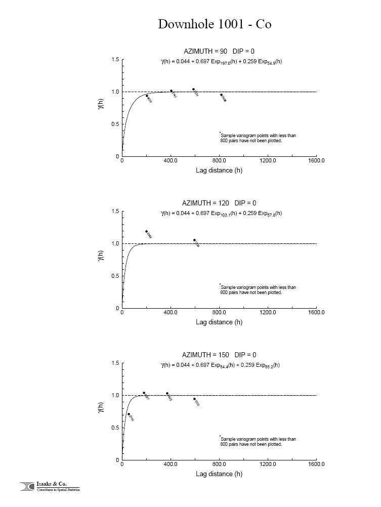
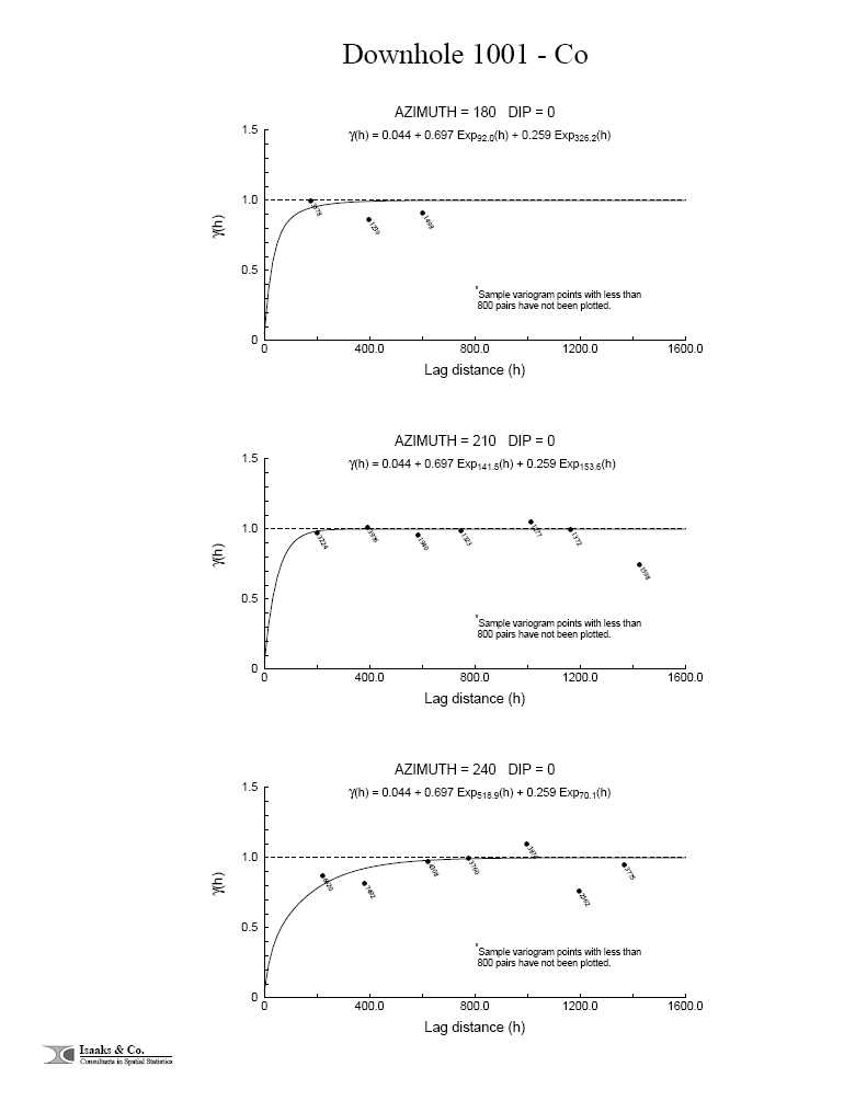


![]()
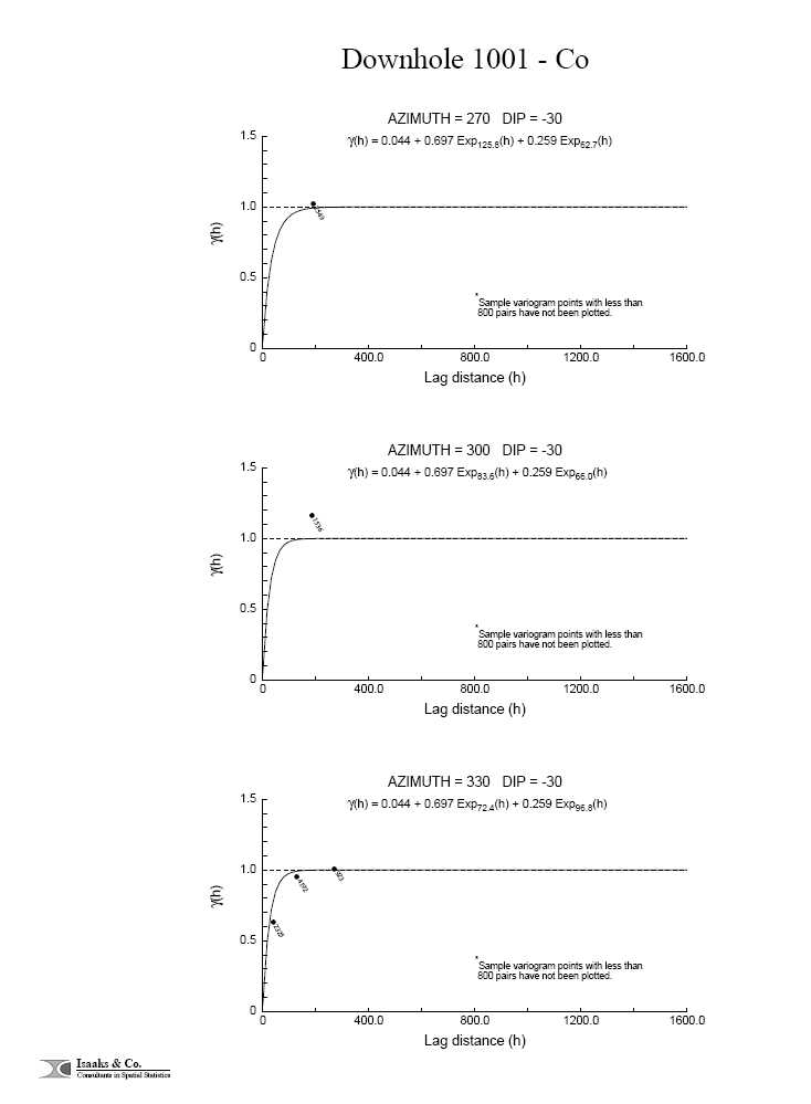
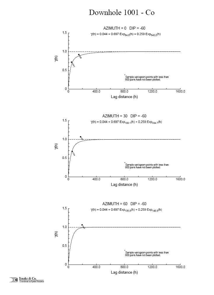


Downhole 1001 - Cu
User Defined Rotation Conventions
| Nugget ==> 0.005 | ||||
| C1 ==> 0.605 | ||||
| C2 ==> 0.390 | ||||
| First Structure -- Exponential with Practical Range | ||||
| RH Rotation about the Z axis ==> -52 | ||||
| RH Rotation about the Y’ axis ==> 105 | ||||
| RH Rotation about the Z’ axis ==> -4 | ||||
| Range along the Z’ axis ==> 23.8 | Azimuth ==> 142 Dip ==> -15 | |||
| Range along the Y’ axis ==> 224.8 | Azimuth ==> 51 Dip ==> -4 | |||
| Range along the X’ axis ==> 78.2 | Azimuth ==> 305 Dip ==> -75 | |||
| Second Structure -- Exponential with Practical Range | ||||
| RH Rotation about the Z axis ==> -169 | ||||
| RH Rotation about the Y’ axis ==> -108 | ||||
| RH Rotation about the Z’ axis ==> 36 | ||||
| Range along the Z’ axis ==> 1421.1 | Azimuth ==> 79 Dip ==> -18 | |||
| Range along the Y’ axis ==> 1835.0 | Azimuth ==> 181 Dip ==> -34 | |||
| Range along the X’ axis ==> 228.4 | Azimuth ==> 146 Dip ==> 51 | |||
| Modeling Criteria | ||||
| Minimum number pairs req’d ==> 500 | ||||
| Sample variogram points weighted by # pairs | ||||

![]()


![]()
Downhole 1001 - Ni
User Defined Rotation Conventions
| Nugget ==> 0.006 | ||||
| C1 ==> 0.600 | ||||
| C2 ==> 0.394 | ||||
| First Structure -- Exponential with Practical Range | ||||
| RH Rotation about the Z axis ==> -8 | ||||
| RH Rotation about the Y’ axis ==> 21 | ||||
| RH Rotation about the Z’ axis ==> 42 | ||||
| Range along the Z’ axis ==> 66.6 | Azimuth ==> 98 Dip ==> 69 | |||
| Range along the Y’ axis ==> 32.9 | Azimuth ==> 328 Dip ==> 14 | |||
| Range along the X’ axis ==> 174.8 | Azimuth ==> 54 Dip ==> -16 | |||
| Second Structure -- Exponential with Practical Range | ||||
| RH Rotation about the Z axis ==> -51 | ||||
| RH Rotation about the Y’ axis ==> -46 | ||||
| RH Rotation about the Z’ axis ==> -5 | ||||
| Range along the Z’ axis ==> 1107.8 | Azimuth ==> 321 Dip ==> 44 | |||
| Range along the Y’ axis ==> 1465.2 | Azimuth ==> 54 Dip ==> 3 | |||
| Range along the X’ axis ==> 202.3 | Azimuth ==> 148 Dip ==> 45 | |||
| Modeling Criteria | ||||
| Minimum number pairs req’d ==> 500 | ||||
| Sample variogram points weighted by # pairs | ||||


![]()


Downhole 1001 - Pd
User Defined Rotation Conventions
| Nugget ==> 0.008 | ||||
| C1 ==> 0.671 | ||||
| C2 ==> 0.321 | ||||
| First Structure -- Exponential with Practical Range | ||||
| RH Rotation about the Z axis ==> -19 | ||||
| RH Rotation about the Y’ axis ==> 15 | ||||
| RH Rotation about the Z’ axis ==> -16 | ||||
| Range along the Z’ axis ==> 67.0 | Azimuth ==> 109 Dip ==> 75 | |||
| Range along the Y’ axis ==> 130.9 | Azimuth ==> 35 Dip ==> -4 | |||
| Range along the X’ axis ==> 24.7 | Azimuth ==> 126 Dip ==> -14 | |||
| Second Structure -- Exponential with Practical Range | ||||
| RH Rotation about the Z axis ==> -77 | ||||
| RH Rotation about the Y’ axis ==> -51 | ||||
| RH Rotation about the Z’ axis ==> 12 | ||||
| Range along the Z’ axis ==> 1325.5 | Azimuth ==> 347 Dip ==> 39 | |||
| Range along the Y’ axis ==> 2099.6 | Azimuth ==> 69 Dip ==> -9 | |||
| Range along the X’ axis ==> 311.6 | Azimuth ==> 148 Dip ==> 50 | |||
| Modeling Criteria | ||||
| Minimum number pairs req’d ==> 800 | ||||
| Sample variogram points weighted by # pairs | ||||

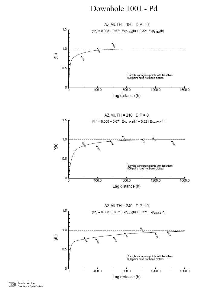
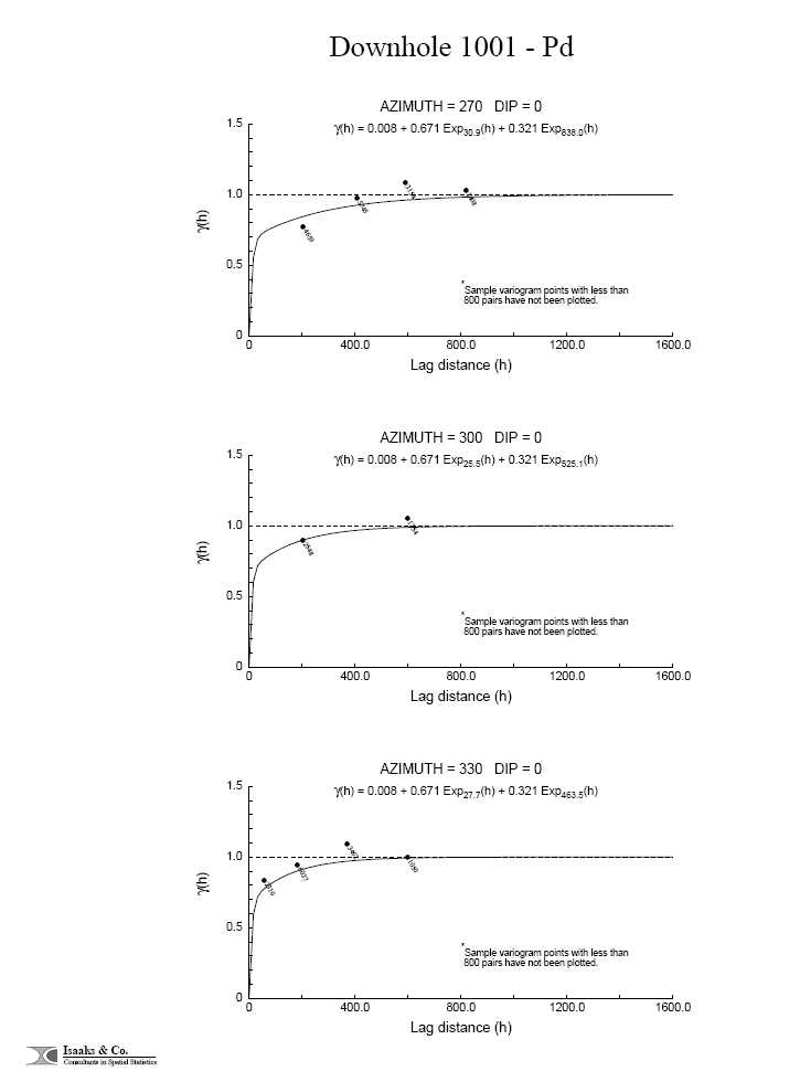
![]()


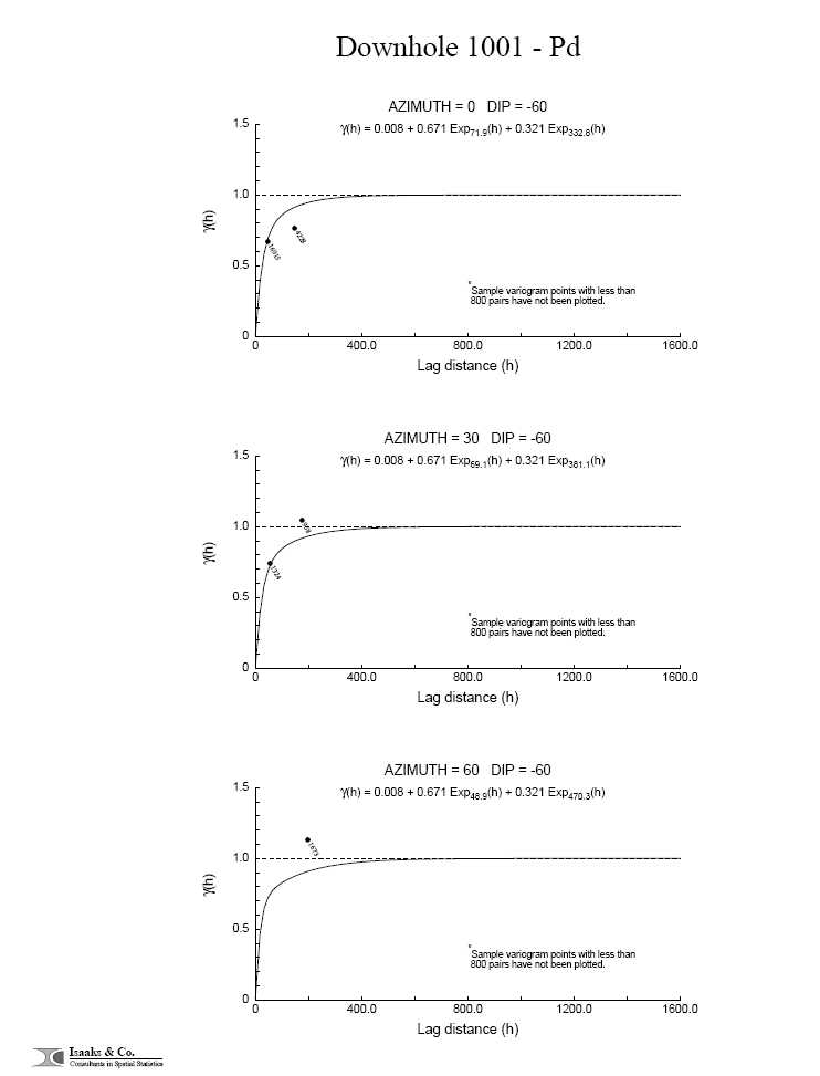


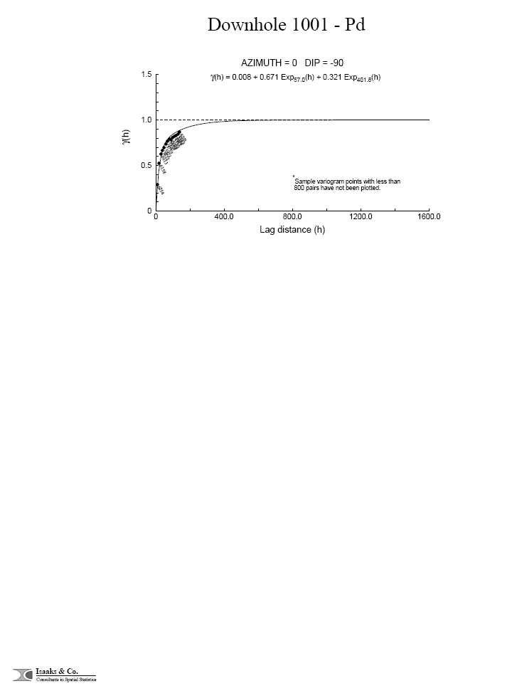
Downhole 1001 - Pt
User Defined Rotation Conventions
| Nugget ==> 0.014 | ||||
| C1 ==> 0.745 | ||||
| C2 ==> 0.241 | ||||
| First Structure -- Exponential with Practical Range | ||||
| RH Rotation about the Z axis ==> -75 | ||||
| RH Rotation about the Y’ axis ==> 21 | ||||
| RH Rotation about the Z’ axis ==> 21 | ||||
| Range along the Z’ axis ==> 72.4 | Azimuth ==> 165 Dip ==> 69 | |||
| Range along the Y’ axis ==> 100.3 | Azimuth ==> 55 Dip ==> 8 | |||
| Range along the X’ axis ==> 19.6 | Azimuth ==> 142 Dip ==> -20 | |||
| Second Structure -- Exponential with Practical Range | ||||
| RH Rotation about the Z axis ==> -117 | ||||
| RH Rotation about the Y’ axis ==> -71 | ||||
| RH Rotation about the Z’ axis ==> 31 | ||||
| Range along the Z’ axis ==> 2685.0 | Azimuth ==> 27 Dip ==> 19 | |||
| Range along the Y’ axis ==> 1483.8 | Azimuth ==> 106 Dip ==> -29 | |||
| Range along the X’ axis ==> 324.8 | Azimuth ==> 145 Dip ==> 54 | |||
| Modeling Criteria | ||||
| Minimum number pairs req’d ==> 500 | ||||
| Sample variogram points weighted by # pairs | ||||
![]()
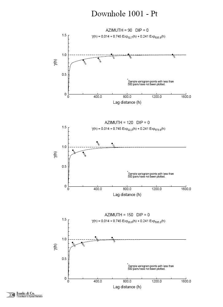


![]()


Downhole 1001 - S
User Defined Rotation Conventions
| Nugget ==> 0.015 | ||||
| C1 ==> 0.558 | ||||
| C2 ==> 0.427 | ||||
| First Structure -- Exponential with Practical Range | ||||
| RH Rotation about the Z axis ==> -59 | ||||
| RH Rotation about the Y’ axis ==> -56 | ||||
| RH Rotation about the Z’ axis ==> 9 | ||||
| Range along the Z’ axis ==> 26.4 | Azimuth ==> 329 Dip ==> 34 | |||
| Range along the Y’ axis ==> 471.4 | Azimuth ==> 54 Dip ==> -7 | |||
| Range along the X’ axis ==> 58.2 | Azimuth ==> 134 Dip ==> 55 | |||
| Second Structure -- Exponential with Practical Range | ||||
| RH Rotation about the Z axis ==> -67 | ||||
| RH Rotation about the Y’ axis ==> 52 | ||||
| RH Rotation about the Z’ axis ==> 51 | ||||
| Range along the Z’ axis ==> 168.7 | Azimuth ==> 157 Dip ==> 38 | |||
| Range along the Y’ axis ==> 1071.9 | Azimuth ==> 30 Dip ==> 38 | |||
| Range along the X’ axis ==> 486.9 | Azimuth ==> 94 Dip ==> -30 | |||
| Modeling Criteria | ||||
| Minimum number pairs req’d ==> 800 | ||||
| Sample variogram points weighted by # pairs | ||||
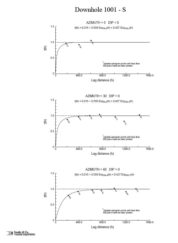
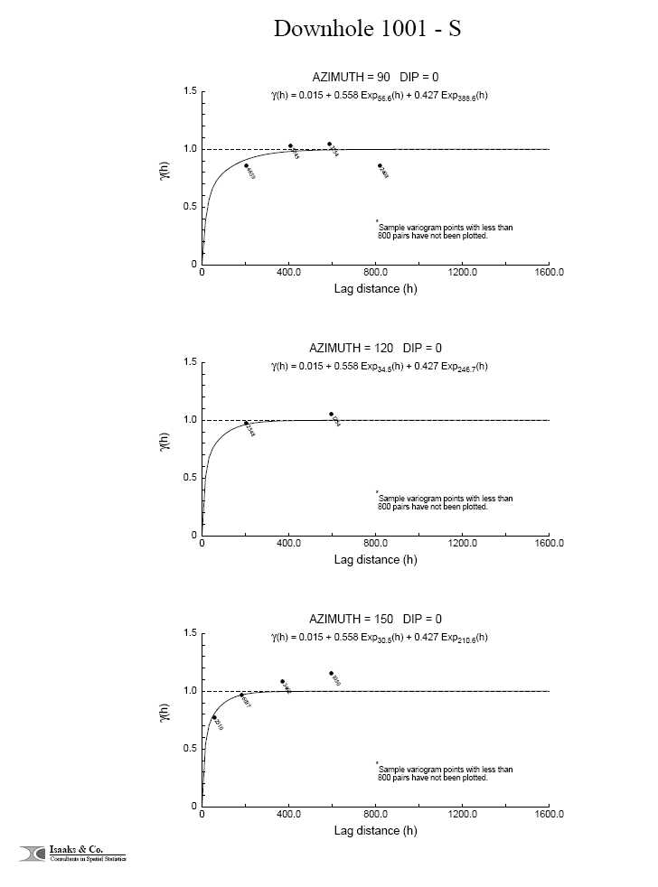


![]()


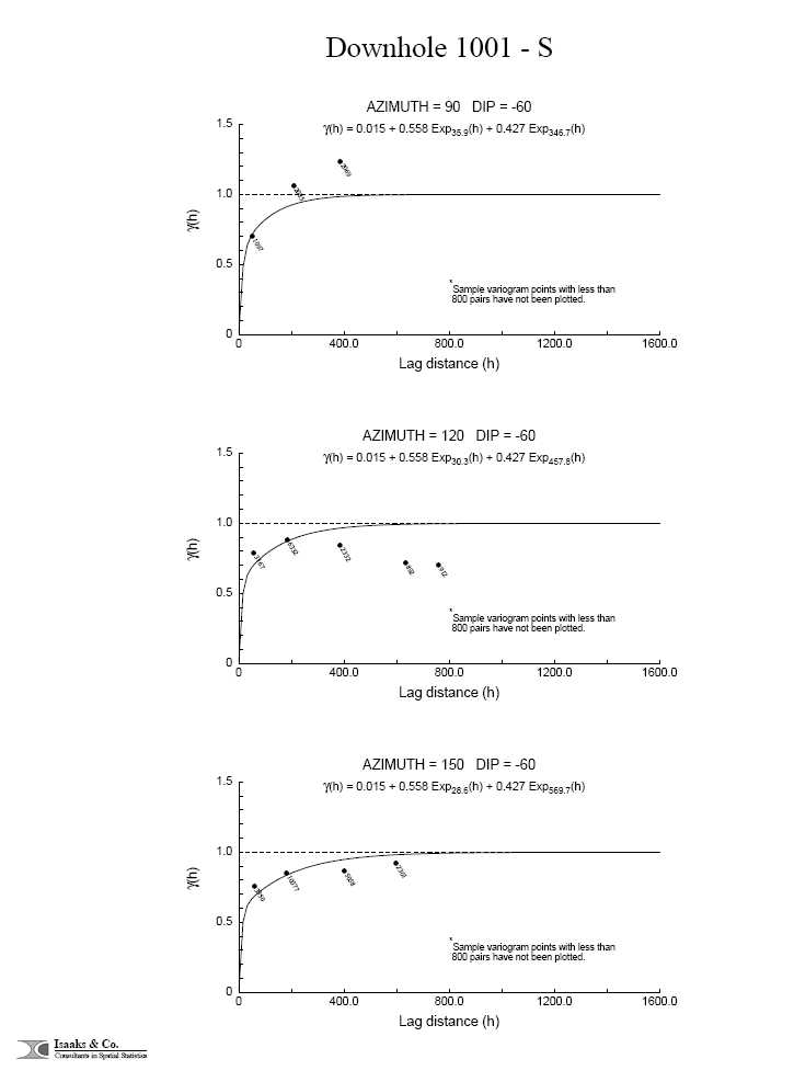


Directional 1003 - Au
User Defined Rotation Conventions
| Nugget ==> 0.013 | ||||
| C1 ==> 0.817 | ||||
| C2 ==> 0.170 | ||||
| First Structure -- Exponential with Practical Range | ||||
| RH Rotation about the Z axis ==> -114 | ||||
| RH Rotation about the Y’ axis ==> -33 | ||||
| RH Rotation about the Z’ axis ==> -39 | ||||
| Range along the Z’ axis ==> 28.5 | Azimuth ==> 24 Dip ==> 57 | |||
| Range along the Y’ axis ==> 60.9 | Azimuth ==> 149 Dip ==> 21 | |||
| Range along the X’ axis ==> 115.7 | Azimuth ==> 249 Dip ==> 25 | |||
| Second Structure -- Exponential with Practical Range | ||||
| RH Rotation about the Z axis ==> -50 | ||||
| RH Rotation about the Y’ axis ==> -55 | ||||
| RH Rotation about the Z’ axis ==> 11 | ||||
| Range along the Z’ axis ==> 2619.4 | Azimuth ==> 320 Dip ==> 35 | |||
| Range along the Y’ axis ==> 604.1 | Azimuth ==> 44 Dip ==> -9 | |||
| Range along the X’ axis ==> 256.0 | Azimuth ==> 122 Dip ==> 53 | |||
| Modeling Criteria | ||||
| Minimum number pairs req’d ==> 800 | ||||
| Sample variogram points weighted by # pairs | ||||


![]()


Directional 1003 - Co
User Defined Rotation Conventions
| Nugget ==> 0.006 | ||||
| C1 ==> 0.626 | ||||
| C2 ==> 0.368 | ||||
| First Structure -- Exponential with Practical Range | ||||
| RH Rotation about the Z axis ==> 29 | ||||
| RH Rotation about the Y’ axis ==> 97 | ||||
| RH Rotation about the Z’ axis ==> -95 | ||||
| Range along the Z’ axis ==> 59.7 | Azimuth ==> 61 Dip ==> -7 | |||
| Range along the Y’ axis ==> 496.6 | Azimuth ==> 204 Dip ==> -82 | |||
| Range along the X’ axis ==> 32.1 | Azimuth ==> 150 Dip ==> 5 | |||
| Second Structure -- Exponential with Practical Range | ||||
| RH Rotation about the Z axis ==> -33 | ||||
| RH Rotation about the Y’ axis ==> 31 | ||||
| RH Rotation about the Z’ axis ==> 67 | ||||
| Range along the Z’ axis ==> 1475.8 | Azimuth ==> 123 Dip ==> 59 | |||
| Range along the Y’ axis ==> 8895.7 | Azimuth ==> 330 Dip ==> 29 | |||
| Range along the X’ axis ==> 36.3 | Azimuth ==> 53 Dip ==> -12 | |||
| Modeling Criteria | ||||
| Minimum number pairs req’d ==> 800 | ||||
| Sample variogram points weighted by # pairs | ||||
| Max allowable drift on head and tail means ==> 1.5 | ||||


Directional 1003 - Cu
User Defined Rotation Conventions
| Nugget ==> 0.028 | ||||
| C1 ==> 0.833 | ||||
| C2 ==> 0.139 | ||||
| First Structure -- Exponential with Practical Range | ||||
| RH Rotation about the Z axis ==> -57 | ||||
| RH Rotation about the Y’ axis ==> -79 | ||||
| RH Rotation about the Z’ axis ==> 61 | ||||
| Range along the Z’ axis ==> 17.3 | Azimuth ==> 327 Dip ==> 11 | |||
| Range along the Y’ axis ==> 254.0 | Azimuth ==> 37 Dip ==> -59 | |||
| Range along the X’ axis ==> 53.6 | Azimuth ==> 63 Dip ==> 29 | |||
| Second Structure -- Exponential with Practical Range | ||||
| RH Rotation about the Z axis ==> -25 | ||||
| RH Rotation about the Y’ axis ==> -37 | ||||
| RH Rotation about the Z’ axis ==> -31 | ||||
| Range along the Z’ axis ==> 1945.7 | Azimuth ==> 295 Dip ==> 53 | |||
| Range along the Y’ axis ==> 3752.6 | Azimuth ==> 51 Dip ==> 18 | |||
| Range along the X’ axis ==> 470.5 | Azimuth ==> 152 Dip ==> 31 | |||
| Modeling Criteria | ||||
| Minimum number pairs req’d ==> 1500 | ||||
| Sample variogram points weighted by # pairs | ||||


![]()


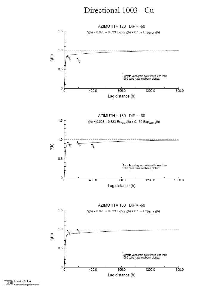


Directional 1003 - Ni
User Defined Rotation Conventions
| Nugget ==> 0.016 | ||||
| C1 ==> 0.559 | ||||
| C2 ==> 0.425 | ||||
| First Structure -- Exponential with Practical Range | ||||
| RH Rotation about the Z axis ==> -69 | ||||
| RH Rotation about the Y’ axis ==> -9 | ||||
| RH Rotation about the Z’ axis ==> -4 | ||||
| Range along the Z’ axis ==> 42.5 | Azimuth ==> 339 Dip ==> 81 | |||
| Range along the Y’ axis ==> 313.7 | Azimuth ==> 73 Dip ==> 1 | |||
| Range along the X’ axis ==> 239.3 | Azimuth ==> 163 Dip ==> 9 | |||
| Second Structure -- Exponential with Practical Range | ||||
| RH Rotation about the Z axis ==> -14 | ||||
| RH Rotation about the Y’ axis ==> -1 | ||||
| RH Rotation about the Z’ axis ==> -32 | ||||
| Range along the Z’ axis ==> 761.3 | Azimuth ==> 284 Dip ==> 89 | |||
| Range along the Y’ axis ==> 1431.6 | Azimuth ==> 46 Dip ==> 1 | |||
| Range along the X’ axis ==> 120.9 | Azimuth ==> 136 Dip ==> 1 | |||
| Modeling Criteria | ||||
| Minimum number pairs req’d ==> 800 | ||||
| Sample variogram points weighted by # pairs | ||||


![]()


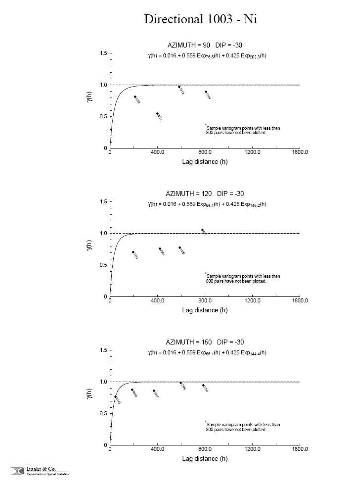
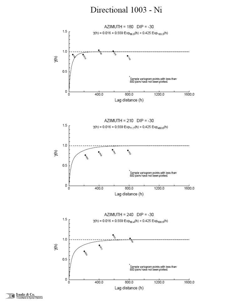


Directional 1003 - Pd
User Defined Rotation Conventions
| Nugget ==> 0.004 | ||||
| C1 ==> 0.790 | ||||
| C2 ==> 0.206 | ||||
| First Structure -- Exponential with Practical Range | ||||
| RH Rotation about the Z axis ==> -35 | ||||
| RH Rotation about the Y’ axis ==> -32 | ||||
| RH Rotation about the Z’ axis ==> 6 | ||||
| Range along the Z’ axis ==> 29.1 | Azimuth ==> 305 Dip ==> 58 | |||
| Range along the Y’ axis ==> 268.8 | Azimuth ==> 30 Dip ==> -3 | |||
| Range along the X’ axis ==> 69.5 | Azimuth ==> 117 Dip ==> 31 | |||
| Second Structure -- Exponential with Practical Range | ||||
| RH Rotation about the Z axis ==> -20 | ||||
| RH Rotation about the Y’ axis ==> -54 | ||||
| RH Rotation about the Z’ axis ==> -21 | ||||
| Range along the Z’ axis ==> 3123.2 | Azimuth ==> 290 Dip ==> 36 | |||
| Range along the Y’ axis ==> 831.6 | Azimuth ==> 32 Dip ==> 17 | |||
| Range along the X’ axis ==> 244.9 | Azimuth ==> 143 Dip ==> 49 | |||
| Modeling Criteria | ||||
| Minimum number pairs req’d ==> 800 | ||||
| Sample variogram points weighted by # pairs | ||||


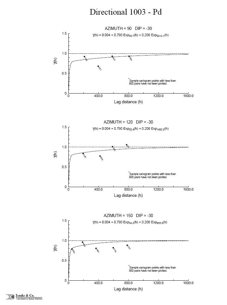


![]()


Directional 1003 - Pt
User Defined Rotation Conventions
| Nugget ==> 0.416 | ||||
| C1 ==> 0.391 | ||||
| C2 ==> 0.193 | ||||
| First Structure -- Exponential with Practical Range | ||||
| RH Rotation about the Z axis ==> -55 | ||||
| RH Rotation about the Y’ axis ==> -55 | ||||
| RH Rotation about the Z’ axis ==> 14 | ||||
| Range along the Z’ axis ==> 11.2 | Azimuth ==> 325 Dip ==> 35 | |||
| Range along the Y’ axis ==> 623.4 | Azimuth ==> 47 Dip ==> -11 | |||
| Range along the X’ axis ==> 149.6 | Azimuth ==> 122 Dip ==> 53 | |||
| Second Structure -- Exponential with Practical Range | ||||
| RH Rotation about the Z axis ==> -40 | ||||
| RH Rotation about the Y’ axis ==> -46 | ||||
| RH Rotation about the Z’ axis ==> -12 | ||||
| Range along the Z’ axis ==> 1920.4 | Azimuth ==> 310 Dip ==> 44 | |||
| Range along the Y’ axis ==> 1340.1 | Azimuth ==> 49 Dip ==> 9 | |||
| Range along the X’ axis ==> 294.3 | Azimuth ==> 147 Dip ==> 44 | |||
| Modeling Criteria | ||||
| Minimum number pairs req’d ==> 800 | ||||
| Sample variogram points weighted by # pairs | ||||


![]()
