Exhibit 10.1
|
|
The Children’s Place |
Creating Logistics Results |
| Dematic |
|
| Proposal for Conveyor System |
Introduction
Dematic’s goal is to provide The Children’s Place with the best system solution available, including cost-effective technologies, control systems, software, visualization systems, integration and services. This will help The Children’s Place to optimize service to its customers, reduce distribution lead-time, enhance material tracking, and support reduction of overall operating costs. We look forward to working together with The Children’s Place to build this innovative Material Handling System.
Executive Summary
This Proposal covers a Material Handling System encompassing conveyor equipment, controls, software, commissioning and training and is summarized with the following tasks.
Project Management
Project Management assures that the material handling system is delivered on time according to the Schedule and coordinates the final design that meets the operational requirements defined in this Proposal. A successful project management plan is accomplished through interactions between Dematic and The Children’s Place Personnel.
Mechanical Engineering
Mechanical Engineering refines the layout drawings that are submitted with this Proposal. They also prepare installation drawings, design nonstandard equipment components, and integrate the standard and nonstandard equipment into an operational system.
Controls Engineering
Controls Engineering provides the development of an electrical controls scheme, selection of controls components, preparation of schematic wiring diagrams, and preparation of detailed Descriptions of Operation(s).
Software Engineering
Software Engineering implements the information technology portion of the system, including programming, integration, testing, training, and Functional Description documentation. Operator manuals are created for the training.
i
Training and Support
· Dematic provides in-depth training to enable Personnel to properly operate and maintain the system
· Dematic provides technical and operational support for the first week of The Children’s Place’s operations
· Extended maintenance support packages are available
· Dematic has an Engineering staff that understands The Children’s Place’s expectations and has the resources to meet The Children’s Place’s needs
· Dematic provides detailed Operations and Maintenance training tailored to The Children’s Place’s specific needs
· Dematic has Customer Service Emergency Support available 24 hours a day, 7 days a week by way of a toll free number
ISO 9001:2000 Registered
Dematic is registered to the ISO-9001:2000 International Standard for Quality Management Systems.
The registration applies to all Dematic Manufacturing, Engineering, Project Management and Customer Service processes.
ii
Revisions
Revision Level |
| Date of Revision |
| Detail of Revision |
|
|
|
|
|
|
| 2006-September-27 |
| Initial Release. |
iii
Table of Contents
1 |
| Title Page |
| 1 |
1.1 |
| Proposal Content |
| 2 |
|
|
|
|
|
2 |
| Scope of Work |
| 3 |
2.1 |
| Design and Engineering |
| 3 |
2.2 |
| Material Handling System |
| 3 |
2.3 |
| Integration |
| 4 |
2.4 |
| Training |
| 4 |
2.5 |
| Documentation |
| 5 |
|
|
|
|
|
3 |
| System Overview |
| 6 |
3.1 |
| System Material Flows |
| 6 |
3.2 |
| Receiving |
| 6 |
3.3 |
| Receiving Merge |
| 7 |
3.4 |
| SKU Sorter |
| 7 |
3.5 |
| Tote Make-up |
| 8 |
3.6 |
| Carton Make-up |
| 8 |
3.7 |
| Tote Sorter |
| 9 |
3.8 |
| Put-to-Light Carton Build Area |
| 9 |
3.9 |
| Tapers and Dunnage |
| 10 |
3.10 |
| Label Print and Apply Area |
| 10 |
3.11 |
| Shipping Sorter |
| 11 |
3.12 |
| Startup-Procedure (Typical) |
| 12 |
3.13 |
| Emergency Stop Procedure (Typical) |
| 12 |
3.14 |
| Accumulation Flow Control (Typical) |
| 12 |
|
|
|
|
|
4 |
| Project Management |
| 13 |
4.1 |
| Project Team Organization |
| 13 |
4.2 |
| Project Scheduling |
| 14 |
4.3 |
| Training |
| 15 |
4.4 |
| Schedule |
| 20 |
|
|
|
|
|
5 |
| Material Handling System |
| 21 |
5.1 |
| Materials to be Handled |
| 21 |
|
|
|
|
|
6 |
| Mechanical Equipment Details |
| 25 |
6.1 |
| C-L Conveyor Components |
| 25 |
6.2 |
| Detailed Mechanical Equipment List |
| 26 |
6.3 |
| Detail Sheets |
| 56 |
6.4 |
| Mechanical Specifications |
| 82 |
|
|
|
|
|
7 |
| Controls Equipment Details |
| 84 |
iv
7.1 |
| C-L100 Integrated Conveying Solution |
| 84 |
7.2 |
| Control Devices |
| 86 |
7.3 |
| E-stops and Interlocking |
| 93 |
7.4 |
| Control Cabinets |
| 94 |
7.5 |
| Standard Controls Hardware |
| 94 |
7.6 |
| GSMi Visualization |
| 95 |
|
|
|
|
|
8 |
| Computer Information System |
| 112 |
8.1 |
| Integrated Software System – Proposal Overview |
| 112 |
8.2 |
| System Deliverables |
| 115 |
8.3 |
| SortDirector Overview |
| 115 |
8.4 |
| PickDirector Overview |
| 122 |
8.5 |
| Project Parameters |
| 127 |
|
|
|
|
|
9 |
| Proposal Specifications |
| 133 |
9.1 |
| General |
| 133 |
9.2 |
| The Children’s Place Deliverables |
| 134 |
|
|
|
|
|
10 |
| Safety |
| 135 |
10.1 |
| Mutual Commitment to Safety |
| 135 |
10.2 |
| OSHA Lockout / Tagout Rules |
| 136 |
|
|
|
|
|
11 |
| Service Support |
| 137 |
11.1 |
| Additional Optional Services Available from Dematic |
| 138 |
|
|
|
|
|
12 |
| System Pricing |
| 142 |
12.1 |
| Base System |
| 142 |
12.2 |
| Pricing Notes |
| 142 |
12.3 |
| Delivery and Shipping Terms |
| 143 |
12.4 |
| Export Laws and Regulations |
| 143 |
12.5 |
| Payment Terms |
| 143 |
12.6 |
| Commercial Terms |
| 144 |
|
|
|
|
|
13 |
| Sales Agreement |
| 145 |
13.1 |
| General Terms and Conditions – Exhibit A |
| 146 |
v
1 Title Page
Dematic Corp. (hereinafter referred to as “Dematic”) with offices located at:
6 Powder Horn Drive
Warren, New Jersey 07059
Submits this Proposal to: |
| Equipment to be installed at: |
The Children’s Place Services Company, LLC |
| The Children’s Place |
(Hereinafter referred to as “The Children’s Place”) |
|
|
915 Secaucus Road |
| Airport Road West |
Secaucus, New Jersey 07094 |
| Fort Payne, Alabama 35968 |
Don Whiteford |
| Don Whiteford |
This Proposal consists of the following:
1. Sales Agreement No. 103522, including General Terms and Conditions - Exhibit A.
2. Sections 1 through 13.
3. Dematic drawings: Q103522-C010, Rev. C, Sheets 1 and 2, Dated September 6, 2006.
4. Other documents: None.
If information in any document conflicts with that in another, governing priority shall be given to documents in the order listed above.
All information in this Proposal is confidential and has been prepared for The Children’s Place’s use solely in considering the purchase of the equipment and/or services described herein. The Children’s Place’s use for any other purpose, or transmission to others of all or any part of this information, including, but not limited to, drawings, process flow diagrams, sequence of operation, and pricing, is unauthorized without Dematic’s prior written consent. All Dematic specifications and drawings remain the property of Dematic and are subject to recall at any time.
© copyright 2006, Dematic Corp. All rights reserved. The contents of this Proposal may not be reproduced without the prior written permission of Dematic Corp.
This Proposal is submitted by:
/s/ Thomas R Dancer |
| Business Development Manager |
| 732 563-1330 ext. 300 |
Thomas Dancer |
| Title |
| Phone |
|
|
|
|
|
/s/ John Van Walleghem |
| General Manager |
| 732 563-1330 ext. 500 |
John Van Walleghem |
| Title |
| Phone |
The Offer Period for this Proposal shall terminate 30 days from the date of this Proposal. Dematic may extend the Offer Period; however, the price, schedule, and other portions of this Proposal may be subject to change. Extensions of the Offer Period shall be valid only if in writing and signed by an authorized Dematic representative. This Proposal shall become binding only upon full execution of the Sales Agreement by duly authorized agents of the parties.
1
1.1 Proposal Content
This Proposal is provided to furnish all of the necessary Hardware and Engineering Services for The Children’s Place material handling system. This Proposal must be purchased with Dematic Proposal Number 104846, which provides all of the necessary Third-party commodities, Mechanical Installation, and Electrical Installation.
This Proposal is summarized as follows:
· Mechanical Design - The refinement of layout drawings submitted with this Proposal, preparation of installation drawings, design of nonstandard equipment components and the integration of the standard and nonstandard equipment into an operational system.
· Air Piping Design - Mechanical drawings will include air-piping diagrams as applicable.
· Control Design - The development of control scheme, selection of control components, preparation of schematic wiring diagrams and preparation of detailed descriptions of operations.
· Computer Design - Development of the computer level of system management scheme, selection of computer components and development of functional specifications.
· Manufacture of Mechanical Equipment - Supplied as specified in the Mechanical Equipment List.
· Manufacture of Controls Equipment - Supplied as specified in Electrical Equipment List.
· Air Piping - Supply field devices such as filters, regulators and piping. Piping to be copper tubing connected to existing air supply system.
2
2 Scope of Work
The following scope of work is intended to be comprehensive, based on Dematic’s knowledge and understanding of the project. The Engineering and Design effort is expected to be a confirmation of the scope listed below. In general, The Children’s Place is responsible for any scope not specifically identified as Dematic’s responsibility.
2.1 Design and Engineering
Dematic Deliverables |
| Comments |
Project Management |
| Coordinate all disciplines and schedule all phases of the project. See the “Project Management” Section for specific details. |
Engineering |
| Layout, design, and proper application of equipment to furnish the Material Handling System described in this Proposal. |
2.2 Material Handling System
Dematic Deliverables |
| Comments |
Mechanical Hardware |
| Consists of the following equipment: |
|
| · (10) Receiving Lines |
|
| · (1) Receiving Slapper Line |
|
| · Receiving Merge and SKU Sorter |
|
| · (32) SKU Divert Lines |
|
| · (4) SKU Sorter Divert Lines To LPA Merge |
|
| · LPA Merge To Shipping Sorter |
|
| · (8) LPA Lines |
|
| · (4) Taper/LPA Lines |
|
| · Tote Build Area With (24) Work Stations |
|
| · Tote Build Take-away Lines To Tote Build Merge |
|
| · Tote Build Merge and Tote Sorter |
|
| · (40) Tote Sorter Divert Lines |
3
Dematic Deliverables |
| Comments |
Mechanical Hardware |
| · (20) PTL Take-away Lines To Shipping Merge |
|
| · Shipping Merge and Sorter |
|
| · (42) Ship Lines |
|
| · (2) New Store Loops |
|
| · (4) Slapper Lines |
|
| See the “Mechanical Equipment Details” Section for specific details. |
Control Hardware |
| Consists of the following equipment: |
|
| · PLC based conveyor control components necessary to operate the conveyor system. |
|
| · RapidSORT Controllers for carton routing on sorters. |
|
| · GSMi Visualization System application software. |
|
| See the “Controls Equipment Details” Section for specific details |
Integrated Computer |
| Interface to The Children’s Place’s WMS |
System |
| · SortDirector and PickDirector applications Software. |
|
| See the “Computer Information Systems” Section for specific details. |
2.3 Integration
Dematic Deliverables |
| Comments |
Complete check-out and integration of all Dematic Deliverables |
| See the “Project Management” Section for full details and description. |
2.4 Training
Dematic Deliverables |
| Comments |
Operator and Maintenance Training for all equipment. |
| Each training session will include classroom and hands-on instruction, and will be conducted during the first shift. See the “Project Management” Section for full details and description. |
Operator and System Administrator Training for all Computer Hardware and Software |
| Each training session will include classroom and hands-on instruction, and will be conducted during the first shift. See the “Project Management” Section for full details and description. |
4
2.5 Documentation
Dematic Deliverables |
| Comments |
System Functional Design Document
|
| Includes a complete description and narrative of the system controls and a |
System Operator Manuals
|
| Detailed description of equipment and system operation, including handling of anomaly conditions and error recovery procedures. Standard Dematic documentation for hardware and software will be provided. |
Equipment Maintenance Manuals
|
| Includes a complete description of equipment operation, troubleshooting, diagnostics, preventive maintenance, and repair procedures. Also included are equipment drawings and electrical schematics as required for maintenance purposes, as well as spare parts listings. |
Software Functional Specification
|
| An approval document for defined software scope to be delivered.
|
5
3 System Overview
3.1 System Material Flows
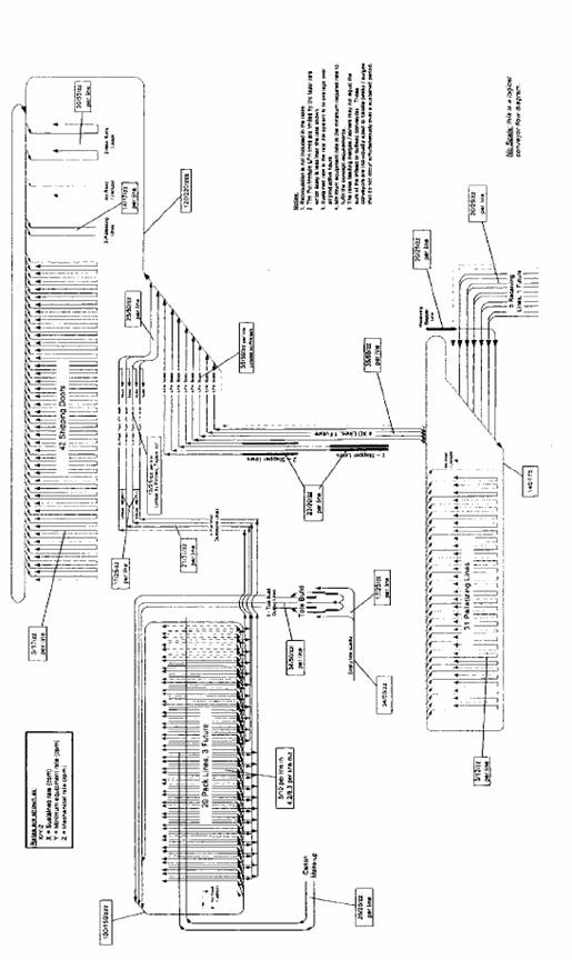
A logical sketch of the proposed system is provided below. The primary purpose of the sketch is to show how product flows throughout the system and identify the major functional areas of the system.
Figure 1 System Flow Diagram
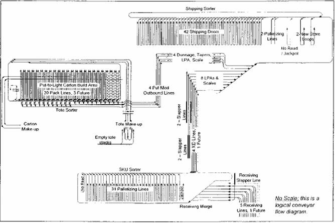
3.2 Receiving
There are 10 receiving doors (2 future doors) and a slapper line. Each pair of receiving doors is serviced by a traversing powered trailer unloader that transports cartons to incline belt conveyor. From the ground level, belt conveyors
6
transport received cartons up to the mezzanine level. When a trailer has been completely unloaded the unloading associate moves the traversing trailer unloader to the other door. The slapper line transports cartons to the Receiving merge from the floor level near the SKU sorter.
Before received cartons and cartons from the slapper line reach the mezzanine level they are transported to a scanner/scale (one for each pair of receiving doors and one for the slapper line). The barcode information and the weight of the received carton are received by SortDirector. SortDirector notifies PkMS the carton has been scanned and supplies the weight of the carton. PkMS in turn sends SortDirector a Divert Directive message that provides the destination of the carton. The possible destinations are:
· A palletizing lane on the SKU sorter
· A palletizing lane on the Shipping sorter
· A store lane on the shipping sorter
· A new store lane on the shipping sorter
The carton continues down the receiving lane to the Receiving merge.
The scanners at receiving are programmed so that if the 4-digit quantity barcode is not correctly scanned the whole label is treated as a no-read.
3.3 Receiving Merge
The receiving merge combines cartons into a single line before induction into the SKU sorter. This merge consists of six (6) induction lines that exit the six (6) scanner/scales and a recirculation line. The scanner/scales receive cartons from the receiving doors and the slapper line. An additional receiving line may be added in the future.
3.4 SKU Sorter
Cartons are released from the Receiving merge onto the SKU sorter. When the carton arrives at the SKU sorter it is scanned by the SKU sorter scanner. The cartons arriving at the SKU sorter have labels with case number barcode and quantity barcode or a shipping label. SortDirector in collaboration with the sorter diverts the carton based on the Divert Directive from PkMS. Upon receiving a divert confirmation form the sorter, SortDirector sends a Divert Confirm message to PkMS.
The cartons are sorted to one of the 31 palletizing lanes or to one of the four cross-dock lanes. The cartons diverted to the cross-dock lanes proceed to the label print and apply (LPA) area. The cartons diverted to the palletizing lanes proceed down to palletizing stations at the end of the lane. The operator at the
7
end of the lane will build one to three SKU pallets. Building pallets and storing them when they are complete is manual and is controlled by PkMS.
Cartons whose label could not be successfully read are diverted to the no-read divert. Cartons that are unknown to SortDirector are routed to the jackpot divert.
3.5 Tote Make-up
There are 24 operator stations in the Tote make-up area. These operator stations are used to fill totes for use in the Put-To-Light area. The 24 stations are arranged in two banks of 12 stations each. Operators remove stacks of empty totes from the empty tote conveyor that is about 5-foot above floor level. Empty totes are scanned and filled with merchandise from corrugate cartons under the direction of PkMS using PkMS controlled equipment. The filled totes are placed on a conveyor that is eighteen-inches in elevation and transported to the tote sorter. There are three conveyors to take away filled totes from each bank of operator stations. When a tote has been filled, PkMS creates and downloads order-putting instructions to the PickDirector System and routing instructions to SortDirector.
There is an empty corrugate (trash) conveyor above the empty tote conveyor. When a carton is emptied of merchandise the operator places the empty corrugate carton onto the empty corrugate conveyor which is at an 87-inch elevation. The empty corrugate conveyor transports corrugate to a compactor. The empty corrugate conveyor will be started each morning and turned off from a pushbutton start/stop switch on the cabinet within line-of-sight of the empty corrugate conveyor system. The conveyor will operate continuously at a fixed speed.
Pallets of product are brought to the tote make-up area under the direction of PkMS. The pallets are deposited on pallet flow rails. The pallets flow toward the operator stations. A metal ramp is provided which allows using a pallet jack to deliver the pallets.
When the empty corrugate conveyor is stopped no additional empty corrugate is to be placed on the conveyor. If the empty corrugate conveyor is loaded when it is stopped motor overloads will occur.
The empty corrugate conveyor is interlocked with the bailer. Specifically the bailer must be on for the empty corrugate conveyor to run. If the bailer is stopped the empty corrugate conveyor stops.
3.6 Carton Make-up
An automatic carton erector builds and labels shipping cartons. Immediately after the carton erector, a pair of scanners verify the labels on each side of the carton match. A red beacon is illuminated if both labels on the carton do not match (or
8
one is a no-read). Operators place the cartons onto one of the two empty carton monorail systems that lead to the Put-to-Light Carton Build Area.
3.7 Tote Sorter
Totes from the six (6) conveyors exiting the Tote Make-up Area merge into three (3) conveyors that feed the Tote Sorter Merge. The recirculation lane from the Tote Sorter Merges with one of the three (3) lanes that feed the Tote Sorter Merge.
The Tote Sorter Merge releases totes onto the tote sorter. When the tote arrives at the tote sorter it is scanned by Tote Sorter Scanner. Totes arriving at the tote sorter have labels contain an 18-character license plate label that will always start with a “T” (Capital T). SortDirector in collaboration with the sorter diverts the tote to the correct pack line based on the Divert Directive from PkMS. Upon receiving a divert confirmation form the sorter, SortDirector sends a Divert Confirm message to PkMS.
3.8 Put-to-Light Carton Build Area
Before operators can work in the put area inbound totes must be built in the make-up tote area. Once a tote’s build process is complete, PkMS sends a message to PickDirector with the inbound tote’s contents and store requirements. The totes are then routed to the pack lines where they are grabbed by the operator and pulled onto the side conveyor spur for processing.
3.8.1 Put Operations
To initiate the put process the operator must first log into their assigned zone by the using the zone’s wireless hand held scanner and personal identification barcode. Next the operator pulls a make-up tote from the infeed line and scans the make-up tote’s barcode label. The associated BayDisplay device in the zone informs the put operator of the tote’s barcode and the number of locations requiring puts the zone. Additionally, the MaxiPick devices will identify the locations and quantities required. The put operator proceeds to each identified location and puts the displayed quantity from the make-up tote to the shipping carton and confirms their action by pressing the “OK” button on the MaxiPick. As the puts are acknowledged PickDirector sends messages to PkMS for each line item put to a shipping carton. The message contains the inbound tote ID, the shipping carton ID, the logical location, quantity requested, quantity put, and the operator.
Where there is insufficient stock at a location to fill the order, the put operator must notify a supervisor to short the location. The supervisor decrements the displayed quantity on the MaxiPick until the display reads the actual quantity put and then must scan a special SHORT barcode to actually short the put. All other lit locations requiring product from the inbound tote will be shorted. If an operator
9
decrements the quantity and presses the “OK” button on the MaxiPick, PickDirector will suspend the make-up tote and the location will not be shorted. Re-scanning the same make-up tote will relight the remaining quantity.
3.8.2 Carton Closing
When a shipping carton has been closed, PickDirector sends PkMS a carton closed message with the store number, shipping carton ID, and status. The put operator pushes the shipping carton out of the put slot onto the outbound conveyor for transport to the Put Label Print and Apply area. The filled shipping carton is transported to the routing sorter. PkMS sends the Print and Apply system the shipping label information and sends SortDirector the destination for the carton. Lastly the put operator assigns an empty shipping carton (obtained from the overhead monorail) to the now empty slot.
When all zones in the put line have been visited the make-up tote should be empty. The empty make-up tote is nested with other make-up totes (up to 4 high) and are placed on the outbound conveyor and transported to the Tapers.
3.9 Tapers and Dunnage
There are tapers and dunnage fill machines on the four conveyor lines that exit the Put-to-Light Carton Build area. Conveyors transport cartons to the dunnage fill and tapers. Operators assist in the operation of the tapers and dunnage fill machines. After the shipping carton is closed and sealed it is transported to the Label Print and Apply area. Stacks of empty totes placed on the conveyors in the put lines are diverted off and routed to the tote make up area prior to the dunnage fill area.
3.10 Label Print and Apply Area
There are two areas of label print and apply. The label print and apply area downstream of the put area has four (4) print and apply line. The label print and apply area receiving product from the SKU sorter, the slapper lines and the cross dock lines have eight (8) print and apply lines.
Cartons arriving at the Print and Apply area from the put area have a case number label pre-applied at Carton Make-up. This case label number is scanned by the Print and Apply Scanner. The Print and Apply System uses its database to determine the shipping label to apply, then prints and applies the label. Immediately down stream of the printer label applicator a verification scanner (a component of the Print and Apply System) reads the label. If the scanned label matches the label that was to be printed the carton continues on to the scanner/scales.
NOTE if the carton is not known to the Print and Apply System a special label will be generated that routes the carton to the jackpot line on the shipping sorter.
10
For the four lines exiting the Put-to-Light Carton Build area, if the label scanned does not match the label that was to be printed, the carton is diverted to the error spur for that print and apply line. An operator removes the carton and determines the nature of the error. If there is a printer problem it is corrected and the carton is placed on a conveyor upstream of the print and apply scanner. If the problem is not caused by a printer problem, the operator must use the PkMS system to determine the nature of the problem and the corrective action to take.
The cross dock lines from the SKU sorter, the slapper lines and the cross dock lines transporting cartons to the Shipping shorter have an LPA area. However these lines to not have separate error correction lines; cartons with incorrect/missing labels will be diverted to the No Read/Jackpot line at the Shipping sorter.
Scales are located after the Print and Apply System and before the shipping merge. The barcode information and the weight of the shipping carton are received by SortDirector. SortDirector notifies PkMS the carton has been scanned and supplies the weight of the carton. PkMS in turn sends SortDirector a Divert Directive message that provides the destination of the carton. The possible destinations are:
· The shipping no read/jackpot lane
· A store lane on the shipping sorter
· A new store lane on the shipping sorter
· A palletizing lane on the shipping sorter
The carton continues down the receiving lane to the shipping sorter merge.
3.11 Shipping Sorter
Totes and cartons from the four (4) conveyors exiting Put-to-Light Carton Build area merge into two (2) lines, the four (4) cross dock lines, and the four (4) slapper lines feed the shipping sorter merge. The recirculation line of the shipping sorter merges with the line exiting the merge.
When a carton arrives at the shipping sorter it is scanned by the Shipping Sorter Scanner. The cartons arriving at the shipping sorter have either a shipping label or a UPS tracking number barcode label. SortDirector in collaboration with the sorter diverts the carton to the correct lane based on the Divert Directive from PkMS. Upon receiving a divert confirmation form the sorter, SortDirector sends a Divert Confirm message to PkMS.
The cartons are sorted to one of the 42 shipping lanes, two (2) palletizing lanes, two (2) new store lanes or the no-read /jackpot lane. The cartons diverted to the new store lanes proceed to the new store loop. The operator at the new store loop will build pallets containing cartons for only a single store. When the pallet is
11
‘complete’ it is stored in the conventional warehouse under the direction of PkMS.
3.12 Startup-Procedure (Typical)
When the main disconnect switch is turned to the “On” position, the conveyors are energized from “Start” pushbutton(s) mounted on the main control panel(s). When a “Start pushbutton is pressed a start-up warning horn sounds for 10 seconds prior to any equipment movement. This is to warn Personnel to stand clear of the equipment. When the horn stops sounding, the equipment will be energized.
3.13 Emergency Stop Procedure (Typical)
Manually actuated emergency stops have been provided at various points along the conveyor system to de-energize the conveyors if an emergency occurs. The emergency stop pushbutton is “Push to Stop” and “Pull to Reset”. The emergency stop pull cords are “Pull to Stop” and must be reset manually at the actuated switch. When actuated, the emergency stops are maintained contact-manual reset and will remain in the actuated position until reset. When the problem has been cleared, the actuated stop must be reset and the conveyor equipment must be restarted at the control panel(s) as previously described.
3.14 Accumulation Flow Control (Typical)
In each area where an accumulation conveyor may be loaded with product by another conveyor, a photoelectric controller with time delay relay is included to stop the preceding conveyor(s) or activate an air operated stop when the accumulation conveyor is fully loaded and the controller is blocked for a preset time. When the accumulation conveyor is allowed to begin discharging its load, the controller will be cleared indicating that space is again available on the accumulation conveyor. When this occurs, the stopped conveyor(s) will be restarted automatically or the air-operated stop will be lowered.
12
4 Project Management
Dematic is committed to the value of effective Project Management in cooperation with The Children’s Place. Each party shares an equal responsibility in quality management of the implementation process. The primary benefit and purpose of effective Project Management is to contain risk for both The Children’s Place and Dematic. Risk will be mutually contained by delivering a system that:
· Meets Specified System Performance
· Imposes Minimal Interruption to Existing Operations
· Provides Reliability and Support
Effective and timely project implementation is heavily influenced by quality Project Management. The fundamental requirements of successful project management are:
· Cooperation
· Communication
· Teamwork
Dematic believes in providing the best products available, unparalleled service, and undivided attention to each Customer’s needs. All Dematic products are manufactured under strict quality procedures. Dematic is registered to the ISO 9001:2000 International Standard for Quality Management Systems. Engineering and Project Management methodologies are also controlled under Dematic’s Quality Management System, ensuring all projects are well managed and stay on schedule.
4.1 Project Team Organization
Upon award of contract, a Project Team will be assigned to the project. The team will have the responsibility for the management and implementation of the entire project from receipt of order through Customer acceptance testing and launch support. The team will be directed by a Project Manager. The Project Manager will have full responsibility for the entire project and will be the Dematic representative for all matters relating to the implementation of the System.
13
4.2 Project Scheduling
In order to effectively co-ordinate the activities of the project implementation, the Project Manager will prepare a detailed Project Schedule. The Project Schedule will be based upon the overall delivery requirements of the schedule outlined in the Proposal document.
During implementation the Project Manager will update the Project Schedule regularly to identify critical activities and ensure proper implementation scheduling. Updates to the Project Schedule are reviewed with The Children’s Place’s Project Manager.
4.2.1 Acceptance Testing
The Dematic Project Manager along with The Children’s Place’s Project Manager will create a System Acceptance Test Plan. The Test Plan defines a systematic approach for each level of required sub-system testing, and the expectations of the specific tests. The Test Plan additionally defines the time periods, personnel, equipment, and test loads that are required for each test.
4.2.1.1 Operational Acceptance
· Conducted under actual or simulated working conditions with The Children’s Place packaging, and labels, and The Children’s Place Supervision, Operational, and Maintenance Personnel operating the system.
· Duration not to exceed five (5) days.
· It should be recognized that during the Operational Acceptance phase, it is likely that adjustments will be required and malfunctions or failures may occur. Any defect in material or workmanship, found during the Operational Acceptance Testing, will be remedied by Dematic as expeditiously as possible.
· It should be recognized that during this Operational Acceptance period, it may not be possible for the mechanized system to function at normal operating levels. This can be due to conditions, beyond Dematic’s control and related to the unavailability of product, skills of Maintenance and Operations Personnel, or the status of supporting logistics. Such conditions will be taken into account in evaluating the results of the testing period.
· Dematic will be on-site during this Operational Acceptance Testing period for the purpose of monitoring results and to provide assistance as conditions dictate.
14
4.2.2 Final Acceptance
After completion of the Acceptance Procedures, Dematic’s Project Manager will furnish The Children’s Place a letter which will address the following:
· The subject system has been accepted. Acceptance may include an agreed to punch-list or set of conditions. Issues not resolved during the acceptance proceedings can be noted in an Action Item List and rectified within an agreed period.
· Confirmation of the commencement of the warranty period.
· Final payment required and due date.
4.3 Training
This section outlines training provided by Dematic for The Children’s Place’s facility. Training will be provided to cover the Automated Material Handling System functional areas, including Operations, Maintenance, and Information Technology.
4.3.1 Business-Linked Learning
Dematic uses a business-linked learning approach in its training design, development, delivery, and evaluation efforts.
4.3.1.1 Dematic’s Approach
Dematic’s business-linked learning approach is shaped by our experience in helping Customers to use learning as a powerful tool to achieve critical business results. Dematic’s learning systems are based on the following principles:
· Learning must be tightly linked to desired business outcomes.
· Business linkage is explicitly understood by learners and made evident by the facilitators of learning.
· The content of learning should be “just-in-time” so that learners can apply their new knowledge and skill soon after learning.
· The content of learning should be “just-enough” providing the correct and right amount of learning content to each audience.
· There must be systems and processes in place to provide timely and constructive feedback to those using new skills on the job.
15
4.3.1.2 Dematic’s Process
To consistently and reliably produce desired business results, Dematic follows an established process for creating learning that is specific to The Children’s Place’s installation and application of Dematic systems (see the following Figure). The following is the outcome for each phase of the business-linked development process.
Analyze – Clearly defined business goals and environmental context
Design – Blended learning solution that is aligned with business goals
Develop – Learning content, activities, and exercises aimed at critical skills and knowledge
Implement – Practice and feedback on performance that mirrors real world performance requirements
Evaluate – Assessment of learner performance and training effectiveness at meeting key business results
Figure 2 Business-Linked Learning Development Process
Analyzer |
| Design |
| Develop |
| Implement |
| Evaluate |
· Identify Customer business goals |
| · Customize learning solution |
| · Review learning solutions with Dematic subject matter experts |
| · Pilot design and learning solution |
| · Assess learner performance |
· Assess Customer work environment and workforce attributes |
| · Manuals |
| · Validate learning solution with customer |
| · Finalize design and learning solution |
| · Assess learning solution effectiveness |
· Assess Customer learning systems |
| · Classes |
|
|
| · Deliver learning solution |
| · Assess business impact of learning |
|
| · Placards |
|
|
|
|
|
|
|
| · Job Aids |
|
|
|
|
|
|
|
| · Simulations |
|
|
|
|
|
|
|
| · Videos |
|
|
|
|
|
|
Using this approach, Managers, Supervisors and Operators should feel highly empowered and confident, learning should be viewed as a valuable tool for success, and individual and team learning should be maximized.
4.3.2 Training Program
4.3.2.1 Operations Training
Dematic’s business-linked learning systems provide critical learning opportunities and experiences for The Children’s Place’s employees. Dematic’s operations learning solutions are directed at three levels within The Children’s Place’s organization — Management, Supervisors and Leads, and Operators. Dematic provides a blended learning solution that covers product flow, design considerations and decisions, system layout and operations, and control devices.
16
System Operations training is provided to give participants an understanding of their assigned area from an operational perspective. Dematic targets critical operations in the assigned functional area while explaining flow control, equipment operation, and control devices. Additionally, discussions focus on upstream and downstream customers, and how individual and area performance can impact those customers.
At the end of this training, Operators should understand the operations of their functional area, the area devices, their upstream and downstream customers, and should be able to start/stop their portion of the system.
Target Audience
Dematic will train ten (10) DC Personnel.
Audiences generally include DC Managers, Operations Supervisors, Operators, and Maintenance Personnel.
Courses
Dematic will provide the following operations courses.
1. Six (6) sessions, approximately 3 hours per session, conducted over two consecutive days — Operations Management Training.
4.3.2.2 Maintenance Training
The maintenance curriculum is designed to cover the mechanical, electrical, and controls aspects of the installed equipment. Topics include safety, equipment construction and installation, equipment operation, maintenance and repair procedures, and technical documentation.
Dematic recommends that all Personnel responsible for maintaining the system be assigned to work with the installation and commissioning crews during their final weeks on-site.
Dematic will conduct formal training courses for the Maintenance Personnel prior to system startup. These training classes will include classroom lectures, audio-visual presentations, and hands-on demonstrations on the installed equipment. Site tours will be conducted to point out common operational issues that affect equipment uptime.
Knowledge gained on common system anomalies can be used to increase system efficiencies.
Target Audience
Dematic will train ten (10) DC Maintenance Personnel.
17
These Personnel must have existing knowledge in mechanical and electrical fundamentals, as well as a solid understanding of maintenance practices and procedures. It is strongly recommended that participants be in attendance for the entire session of each course.
Courses
Dematic will provide the following maintenance courses:
1. One (1) session, approximately 3 days per session, conducted over three consecutive days, first shift only – Conveyor Maintenance – Mechanical.
2. One (1) session, approximately 3 days per session, conducted over three consecutive days, first shift only – Conveyor Maintenance – Electrical Controls.
4.3.2.3 Information Systems Training
Information System training is provided to cover the computer hardware and software aspects of The Children’s Place’s Automated Material Handling System. Software Application Engineering (SAE) topics include system administration, data storage, computer system operation, and other computer related tasks.
Participants can use the skills and knowledge gained in this curriculum to perform administration, support, and troubleshooting procedures on computer system equipment and applications. Knowledge gained in computer system areas can be used to increase system uptime and fault recovery.
Target Audience
Dematic will train ten (10) DC Personnel.
Audiences generally include Network Administrators, Operations Supervisors, Key Operators, and Maintenance Supervisors.
Courses
Dematic will provide the following information systems courses:
1. Six (6) sessions, conducted over two (2) consecutive days, first shift only, (2 hours per session) – SortDirector Administrator.
18
4.3.3 The Children’s Place Requirements
The Children’s Place is to provide the following to support the training program:
4.3.3.1 Learner Availability
4.3.3.1.1 Management Responsibility
It is important for DC management to ensure that Learners and their Supervisors are informed of scheduled training dates and times. Dematic looks to DC Management to support us in Dematic’s coordination efforts by communicating the importance of training to their staff.
4.3.3.1.2 Learner Responsibility
It is important that Learners are prepared and at the training location on time. Supervisors should understand, in advance, that their Personnel will be unavailable for work during training periods. This prevents the disruption of training and ensures that all Learners have the opportunity to learn critical conveyor system related job skills.
4.3.4 Facilities and Equipment
4.3.4.1 Training Room
For all training sessions, Dematic requires The Children’s Place to provide a well-lit training room. Sufficient space and seating arrangements should be made based on the number of people attending.
· Operations Training – seating for 10
· Maintenance Training – seating for 10
· Information Systems Training – seating for 10
4.3.4.2 Equipment
For all training sessions, Dematic requires The Children’s Place to provide the following equipment:
· Television and VCR
· White board
· Dry-erase markers and eraser
· Safety equipment (if necessary) for site tours
19
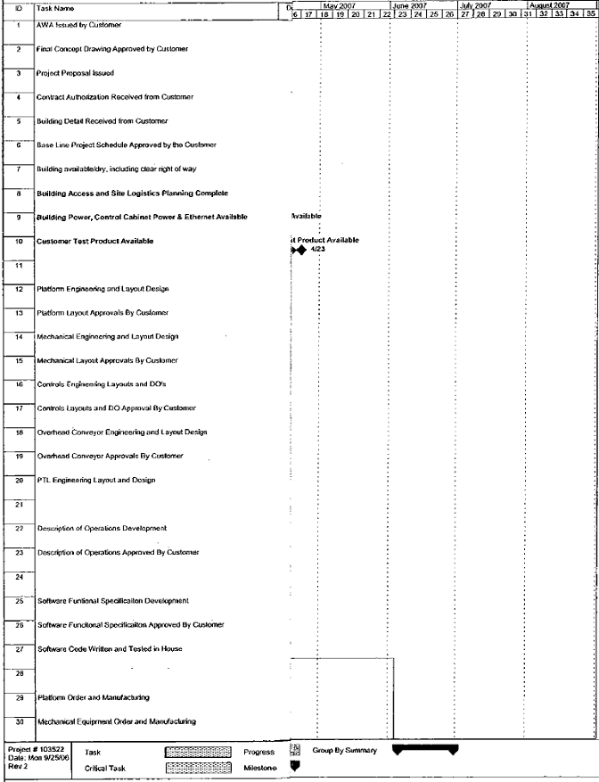
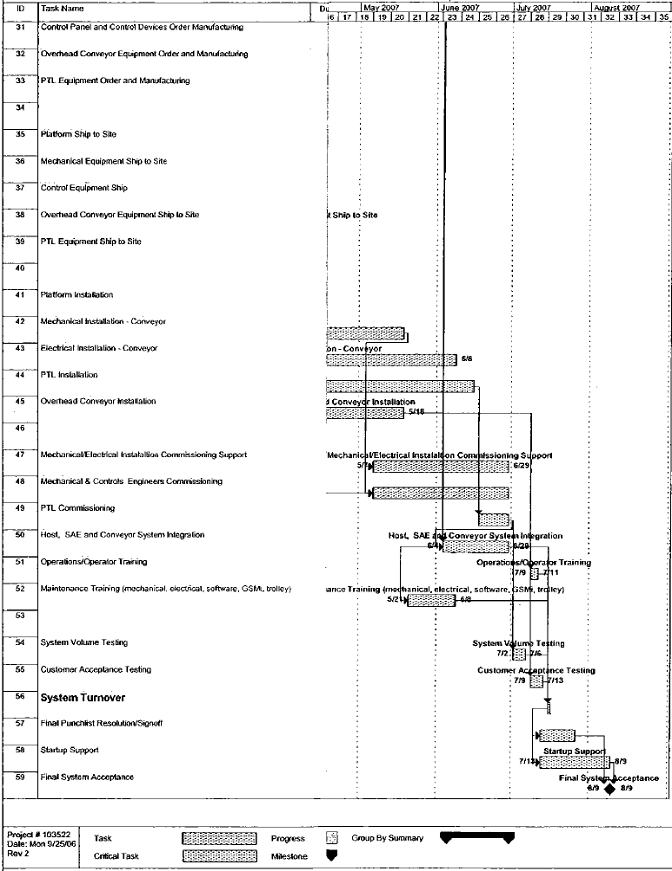
4.4 Schedule
The Preliminary Project Schedule indicating milestone dates is provided on the following page.
20
| Proposal for Conveyor System |
5 Material Handling System
The equipment will perform as described in this Proposal, when properly managed, operated, and maintained. Please refer to the Dematic drawings referenced on the Title Page of this Proposal while reviewing the rate and equipment listings.
5.1 Materials to be Handled
The system design is based on the following material and rate specifications.
5.1.1 Physical Load Characteristics
The equipment will convey materials having the dimensions, weights, shapes, surfaces and other characteristics, as set forth in this Section. The equipment will have the mechanical capability to convey such materials at the rates specified in this Section.
The items to be conveyed will have the following physical properties:
5.1.1.1 Carton Parameters
| Length |
| Width |
| Height |
| Weight |
| |
Shipping Carton |
| 18.5 | ” | 16.25 | ” | 15.5 | ” | 40 lbs. |
|
Vendor Carton |
|
|
|
|
|
|
|
|
|
Minimum |
| 9 | ” | 7 | ” | 4.5 | ” | 2 lbs. |
|
Standard |
| 22 | ” | 16 | ” | 15 | ” | 25 lbs. |
|
Maximum |
| 34 | ” | 22 | ” | 16 | ” | 70 lbs. |
|
* Package weight cannot exceed 33 pounds per lineal foot, and cannot exceed 110 pounds per package.
NOTE |
| 1. |
| The shipping carton has 8” top flaps that will be tabbed down. |
|
|
|
|
|
|
| 2. |
| Vendor carton information is from the Dayton, New Jersey facility conveyor drawings. |
21
5.1.1.2 Put Tote Parameters
| Length |
| Width |
| Height |
| Weight |
| |
Top |
| 24 | ” | 20 | ” | 12 | ” | 30 lbs. |
|
Bottom |
| 21 | ” | 17.5 | ” | 12 | ” | 30 lbs. |
|
5.1.1.3 Pallet Parameters
Pallets are not handled by the mechanized material handling system.
| Length |
| Width |
| Height |
| Weight |
| |
Receiving Pallet |
| 40 | ” | 48 | ” | 4” (empty) |
| 450 lbs. |
|
Storage Pallet |
| 40 | ” | 48 | ” | 4” (empty) |
| 450 lbs. |
|
Shipping Pallet |
| 40 | ” | 48 | ” | 4” (empty) |
| 450 lbs. |
|
NOTES
1. The weights and sizes listed in the Table are for equipment design only and are not to be used to determine what The Children’s Place’s Personnel can lift, carry, or move.
2. The materials being conveyed are to be presented with the maximum dimension in the direction of travel and the minimum dimension perpendicular to the conveyor surface.
3. The materials to be conveyed must be in a condition to allow for proper conveyance. The bottom surface, in contact with the conveyor, must be firm and flat, free of distortion, and of sufficient strength to support its own weight.
4. Items which may not convey reliably are those with the following characteristics:
· Uneven bottoms, soft bottoms, or bottoms with banding or strapping
· Open or improperly sealed containers
· Imperfections of the conveyed product
· Side or bottom which has concave or convex distortion
· Protrusions on the sides or bottom
· Uneven weight distribution or shifting center of gravity
22
5.1.2 Product Flow Rate
It is the responsibility of Dematic to provide equipment that is mechanically capable of conveying the specified units per minute through the sortation system. The ability to obtain these rates is predicated on The Children’s Place’s equipment and Personnel being able to load and unload product to achieve these rates.
The following flow diagram represents the contract equipment rates, using the average for the material which will flow through the area.
NOTE
· The equipment will perform as described when properly operated, maintained and managed by The Children’s Place.
· Manual assistance may be required to initiate and/or maintain the flow of product on gravity conveyor. It is understood that due to the inherent characteristics of gravity conveyor, free flow of product may not occur at all times.
23
24
6 Mechanical Equipment Details
This Section contains technical descriptions of the Material Handling Equipment that will be provided as part of the material handling system supplied to The Children’s Place on both the 103522 and 104846 projects.
The following items are described in this Section:
1. C-L Conveyor Components
2. Detailed Mechanical Equipment List
3. Detail Sheets
4. Mechanical Specifications
5. Platform Specifications
6.1 C-L Conveyor Components
6.1.1 Conveyor Sides
The C-L100 Conveyor sides are made up of two parts; a common extruded aluminum guide channel, and a common extruded aluminum side channel. The guide channel is stacked over the side channel and held together by metal spring clips. This creates an upper and lower section. The conveyor side accepts plastic covers which cover and protect the control components mounted in the side channel.
6.1.2 Conveyor Frame
Two common conveyor sides are connected together with cross members. The Conveyors are available in three different frame widths: 550 mm (22 inches), 750mm (30 inches), and 900mm (35 inches). This dimension is measured outside to outside. The actual conveyor width is 80mm (3 inches) less than each frame.
6.1.3 Interrupter Plates
The Interrupter plates are high density plastic plates that attach to the conveyor sides. Interrupter plates are located at bed joints and at a maximum of every three meters. Interrupter plates have several pre-set knockouts to allow the mounting and wiring of control stations, beacons, and other field devices on to the side of the conveyor.
25
6.1.4 T-Bar Connectors
Steel T-Bar Connectors are used to connect the conveyor frames together. There are two types of T-Bar connectors—Long T-Bars bars and Short T-Bars. The Long T-Bar Connectors slide into the upper section of the guide channels and the lower section of the side channels. The short T-Bar Connectors are used in the upper section of the side channels (middle), and on curves. Both types of connectors are locked into place with stamped steel set screws. The connectors have serrated ridges milled into the upper surface of the Ts to ensure that the T-Bar will bite into the aluminum conveyor channel to hold the sections securely together. This connection also provides electrical continuity between the conveyor sections.
6.2 Detailed Mechanical Equipment List
The Mechanical Equipment List for your system follows in its entirely.
26
|
|
|
|
|
|
|
|
|
|
|
|
|
|
|
|
|
| OAL |
|
|
| Elevation |
|
|
|
|
|
|
| Unit number |
|
|
|
|
| W |
| Sppt |
| Mtr |
| Mtr |
| (ft- |
| Speed |
| IN / OUT |
| G.R. |
|
|
| ||
Qty |
| from |
| thru |
| Model |
| Description |
| (in) |
| Typ |
| (HP) |
| Opt |
| in/deg) |
| (fpm) |
| (ft-in) |
| rows |
| Comment |
|
|
|
|
|
|
|
|
|
|
|
|
|
|
|
|
|
|
|
|
|
|
|
|
|
|
|
|
|
Area: RECIEVING LINES TO RECIEVING MERGE. |
| ||||||||||||||||||||||||||
5 |
| TU+ 100001 |
| 100081 |
| 3050 |
| Traversing Cantilevered |
| 24 |
| F |
| 2/1 |
|
|
| 80'-0" |
| 80 |
| 3'-6"/4'-0" |
| N |
| Traversing Cantilevered |
|
5 |
| BT+ 100002 |
| 100082 |
| 410 |
| Belt-on-Roller Incline |
| 24 |
| P |
| 1 |
| B |
| 21'-9" |
| 90 |
| 4'-0"/10'-0" |
| G22 - |
| With Noseover - Power Tail Not Req’d. |
|
1 |
| BA+ 100003 |
|
|
| GPC.01 |
| 50mm Segmented BOR |
| 29.5 |
|
|
| 1 |
|
|
| 10'-3"90° |
| 120.00 |
| 10'-0" |
| F22 - |
| w/ [1] 90o Curve |
|
1 |
| BT+ 100004 |
|
|
| GPC.09 |
| BOS End Drive |
| 29.5 |
|
|
| 1 |
|
|
| 17'-3" |
| 120.00 |
| 10'-0" |
| F22 - |
|
|
|
1 |
| BA+ 100005 |
|
|
| GPC.01 |
| 50mm Segmented BOR |
| 29.5 |
|
|
| 1 |
|
|
| 11'-0"45° |
| 120.00 |
| 10'-0" |
| F22 - |
| w/ [1] 45 o Curves & Junction |
|
1 |
| BT+ 100006 |
|
|
| CL200BOR |
| Belt on Roller |
| 29.5 |
| C/P |
| 3 |
| B |
| 38'-5" |
| 120.00 |
| 10'-0"/20'-6" |
| F22 - |
| w/ Power Tail & Noseover |
|
1 |
| RA+ 100007 |
|
|
| CL200RA |
| Roller Accumulation |
| 29.5 |
| P |
| 2 |
|
|
| 68'-0" |
| 120.00 |
| 20'-6" |
| F11 - |
| w/ Aligner Bed, DZC |
|
5 |
| BA+ 100008 |
| 100088 |
| GPC.01 |
| 50mm Segmented BOR |
| 29.5 |
| P |
| 1 |
|
|
| 9'-10" |
| 120.00 |
| 20'-6" |
| F11 - |
|
|
|
5 |
| AP+ 100009 |
| 100089 |
| Scale |
| In-Line Scale W/ Conveyor Deck |
| 24 |
|
|
|
|
|
|
| 4'-0" |
|
|
| 20'-6" |
| G11 - |
| Gravity: 3" Roller Ctrs Mounted On Scale |
|
1 |
| RA+ 100010 |
|
|
| CL200RA |
| Roller Accumulation |
| 29.5 |
| P |
| 2 |
|
|
| 130'-0" |
| 180.00 |
| 20'-6" |
| F11 - |
| w/ Aligner Bed, DZC |
|
5 |
| BA+ 100011 |
| 100091 |
| GPC.01 |
| 50mm Segmented BOR |
| 29.5 |
| P |
| 1 |
|
|
| 9'-10" |
| 180.00 |
| 20'-6" |
| F11 - |
|
|
|
5 |
| BT+ 100012 |
| 100092 |
| CL200BOR |
| Belt on Roller |
| 29.5 |
| P |
| 2 |
|
|
| 48'-1" |
| 180.00 |
| 20'-6" |
| F11 - |
| w/ Power Tail |
|
5 |
| RT+ 100013 |
| 100093 |
| 2490 |
| SSLI Live Roller Wedge |
| 30 |
| P |
| 1 |
|
|
| 7'-6" |
| 180 |
| 20'-6n |
| G11 - |
|
|
|
1 |
| BA+ 100023 |
|
|
| GPC.01 |
| 50mm Segmented BOR |
| 29.5 |
|
|
| 1 |
|
|
| 15'-8"90° |
| 120.00 |
| 10'-0" |
| F22 - |
| w/ [1] 90° Curve |
|
27
|
|
|
|
|
|
|
|
|
|
|
|
|
|
|
|
| OAL |
|
|
| Elevation |
|
|
|
|
| |
|
| Unit number |
|
|
|
|
| W |
| Sppt |
| Mtr |
| Mtr |
| (ft- |
| Speed |
| IN / OUT |
| G.R. |
|
|
| ||
Qty |
| from |
| thru |
| Model |
| Description |
| (in) |
| Typ |
| (HP) |
| Opt |
| in/deg) |
| (fpm) |
| (ft-in) |
| rows |
| Comment |
|
|
|
|
|
|
|
|
|
|
|
|
|
|
|
|
|
|
|
|
|
|
|
|
|
|
|
|
|
1 |
| BT+ 100024 |
|
|
| GPC.09 |
| BOS End Drive |
| 29.5 |
|
|
| 1 |
|
|
| 17'-3" |
| 120.00 |
| 10'-0" |
| F22 - |
|
|
|
1 |
| BT+ 100025 |
|
|
| GPC.09 |
| BOS End Drive |
| 29.5 |
|
|
| 1 |
|
|
| 12'-4" |
| 120.00 |
| 10'-0" |
| F22 - |
|
|
|
1 |
| BA+ 100026 |
|
|
| GPC.01 |
| 50mm Segmented BOR |
| 29.5 |
|
|
| 1 |
|
|
| 16'-5"45° |
| 120.00 |
| 10'-0" |
| F22 - |
| w/ [1] 45° Curve & Junction |
|
1 |
| BT+ 100027 |
|
|
| CL200BOR |
| Belt on Roller |
| 29.5 |
| C/P |
| 3 |
| B |
| 38'-5" |
| 120.00 |
| 10-0"/20'-6" |
| F22 - |
| w/ Power Tail & Noseover |
|
1 |
| RA+ 100028 |
|
|
| CL200RA |
| Roller Accumulation |
| 29.5 |
| P |
| 2 |
|
|
| 50'-0" |
|
|
| 20'-6" |
| F11 - |
| w/ Aligner Bed, DZC |
|
1 |
| RA+ 100031 |
|
|
| CL200RA |
| Roller Accumulation |
| 29.5 |
| P |
| 2 |
|
|
| 168'-0" |
| 180.00 |
| 20'-6" |
| F11 - |
| w/ Aligner Bed, DZC |
|
1 |
| BA+ 100043 |
|
|
| GPC.01 |
| 50mm Segmented BOR |
| 29.5 |
|
|
| 2 |
|
|
| 20'-11"90° |
| 120.00 |
| 10'-0" |
| F22 - |
| w/ [1] 90° Curve |
|
1 |
| BT+ 100044 |
|
|
| GPC.09 |
| BOS End Drive |
| 29.5 |
|
|
| 1 |
|
|
| 17'-3" |
| 120.00 |
| 10'-0" |
| F22 - |
|
|
|
1 |
| BA+ 100045 |
|
|
| GPC.01 |
| 50mm Segmented BOR |
| 29.5 |
|
|
| 2 |
|
|
| 21'-8"45° |
| 120.00 |
| 10'-0" |
| F22 - |
| w/ [1] 45° Curve & Junction |
|
1 |
| BT+ 100046 |
|
|
| CL200BOR |
| Belt on Roller |
| 29.5 |
| C/P |
| 3 |
| B |
| 39'-8" |
| 120.00 |
| 9'-7"/20'-6" |
| F22 - |
| w/ Power Tail & Noseover |
|
1 |
| RA+ 100047 |
|
|
| CL200RA |
| Roller Accumulation |
| 29.5 |
| P |
| 2 |
|
|
| 60'-0" |
|
|
| 20'-6" |
| F11 - |
| w/ Aligner Bed, DZC |
|
1 |
| RA+ 100050 |
|
|
| CL200RA |
| Roller Accumulation |
| 29.5 |
| P |
| 2 |
|
|
| 189'-0" |
| 180.00 |
| 20'-6" |
| F11 - |
| w/ Aligner Bed, DZC |
|
1 |
| BA+ 100063 |
|
|
| GPC.01 |
| 50mm Segmented BOR |
| 29.5 |
|
|
| 3 |
|
|
| 27'-6"90° |
| 120.00 |
| 10'-0" |
| F22 - |
| w/ [1] 90° Curve |
|
1 |
| BT+ 100064 |
|
|
| GPC.09 |
| BOS End Drive |
| 29.5 |
|
|
| 1 |
|
|
| 17'-3" |
| 120.00 |
| 10'-0" |
| F22 - |
|
|
|
1 |
| BA+ 100065 |
|
|
| GPC.01 |
| 50mm Segmented BOR |
| 29.5 |
|
|
| 2 |
|
|
| 28'-3"45° |
| 120.00 |
| 10'-0" |
| F22 - |
| w/ [1] 45° Curve & Junction |
|
1 |
| BT+ 100066 |
|
|
| CL200BOR |
| Belt on Roller |
| 29.5 |
| C/P |
| 3 |
| B |
| 40'-7" |
| 120.00 |
| 10'-0"/20'-6" |
| F22 - |
| w/ Power Tail & Noseover |
|
1 |
| RA+ 100067 |
|
|
| CL200RA |
| Roller Accumulation |
| 29.5 |
| P |
| 2 |
|
|
| 70'-0" |
|
|
| 20'-6" |
| F11 - |
| w/ Aligner Bed, DZC |
|
1 |
| RA+ 100070 |
|
|
| CL200RA |
| Roller Accumulation |
| 29.5 |
| P |
| 2 |
|
|
| 196'-0" |
| 180.00 |
| 20'-6" |
| F11 - |
| w/ Aligner Bed, DZC |
|
1 |
| BA+ 100083 |
|
|
| GPC.01 |
| 50mm Segmented BOR |
| 29.5 |
|
|
| 4 |
|
|
| 32'-10"90° |
| 120.00 |
| 10'-0" |
| F22 - |
| w/ [1] 90° Curve |
|
28
|
|
|
|
|
|
|
|
|
|
|
|
|
|
|
|
| OAL |
|
|
| Elevation |
|
|
|
|
| |
|
| Unit number |
|
|
|
|
| W |
| Sppt |
| Mtr |
| Mtr |
| (ft- |
| Speed |
| IN / OUT |
| G.R. |
|
|
| ||
Qty |
| from |
| thru |
| Model |
| Description |
| (in) |
| Typ |
| (HP) |
| Opt |
| in/deg) |
| (fpm) |
| (ft-in) |
| rows |
| Comment |
|
|
|
|
|
|
|
|
|
|
|
|
|
|
|
|
|
|
|
|
|
|
|
|
|
|
|
|
|
1 |
| BT+ 100084 |
|
|
| GPC.09 |
| BOS End Drive |
| 29.5 |
|
|
| 1 |
|
|
| 17'-3" |
| 120.00 |
| 10'-0" |
| F22 - |
|
|
|
1 |
| BA+ 100085 |
|
|
| GPC.01 |
| 50mm Segmented BOR Accumulation |
| 29.5 |
|
|
| 3 |
|
|
| 33'-7"45° |
| 120.00 |
| 10'-0" |
| F22 - |
| w/ [1] 45° Curve & Junction |
|
1 |
| BT+ 100086 |
|
|
| CL200BOR |
| Belt on Roller |
| 29.5 |
| C/P |
| 3 |
| B |
| 40'-8" |
| 120.00 |
| 10'-0"/20'-6" |
| F22 - |
| w/ Power Tail & Noseover |
|
1 |
| RA+ 100087 |
|
|
| CL200RA |
| Roller Accumulation |
| 29.5 |
| P |
| 2 |
|
|
| 69'-0" |
|
|
| 20'-6" |
| F11 - |
| w/ Aligner Bed, DZC |
|
1 |
| RA+ 100090 |
|
|
| CL200RA |
| Roller Accumulation |
| 29.5 |
| P |
| 2 |
|
|
| 217'-0" |
| 180.00 |
| 20'-6" |
| F11 - |
| w/ Aligner Bed, DZC |
|
|
| ||||||||||||||||||||||||||
Area: RECIEVING SLAPPER LINE. |
| ||||||||||||||||||||||||||
1 |
| RT+ 100101 |
|
|
| 1102 |
| Belt-Driven LR |
| 24 |
| F |
| 1 |
|
|
| 30'-0" |
| 90 |
| 2'-6" |
| G1L - |
|
|
|
1 |
| BT+ 100102 |
|
|
| CL200BOR |
| Belt on Roller |
| 29.5 |
| C/F |
| 5 |
| B |
| 58'-4" |
| 120.00 |
| 2'-6"/17'-4" |
| F22 - |
| w/ Power Feeder & Noseover |
|
1 |
| RA+ 100103 |
|
|
| GPC.02 |
| 50mm O-Ring Accumulation |
| 29.5 |
| C |
| 4 |
|
|
| 16'-6"180° |
| 120.00 |
| 17'-4" |
| F22 - |
| w/ [2] 90° Curves |
|
1 |
| BT+ 100104 |
|
|
| CL200BOR |
| Belt on Roller |
| 29.5 |
| C |
| 1 |
| B |
| 21'-4" |
| 120.00 |
| 17'-4"/20'-6" |
| F22 - |
| w/ Power Tail & Noseover |
|
1 |
| BA+ 100105 |
|
|
| GPC.01 |
| 50mm Segmented BOR Accumulation |
| 29.5 |
| P |
| 3 |
|
|
| 10'-9"90° |
|
|
| 20'-6" |
| F11 - |
| w/ 90° Curve |
|
1 |
| RA+ 100106 |
|
|
| CL200RA |
| Roller Accumulation |
| 29.5 |
| P |
| 2 |
|
|
| 60'-0" |
| 120.00 |
| 20'-6" |
| F11 - |
| w/ Aligner Bed, DZC |
|
1 |
| BA+ 100107 |
|
|
| GPC.01 |
| 50mm Segmented BOR Accumulation |
| 29.5 |
| P |
| 1 |
|
|
| 9'-10" |
| 120.00 |
| 20'-6" |
| F11 - |
|
|
|
1 |
| AP+ 100108 |
|
|
|
|
| In-Line Scale W/ Conveyor Deck |
| 24 |
|
|
|
|
|
|
| 4'-0" |
|
|
| 20'-6" |
| G11 - |
| Gravity: 3" Roller Ctrs Mounted On Scale Includes Receiving Scale & Controller |
|
1 |
| RA+ 100109 |
|
|
| CL200RA |
| Roller Accumulation |
| 29.5 |
| P |
| 2 |
|
|
| 91'-0" |
| 180.00 |
| 20'-6" |
| F11 - |
| w/ Aligner Bed, DZC |
|
1 |
| BA+ 100110 |
|
|
| GPC.01 |
| 50mm Segmented BOR Accumulation |
| 29.5 |
| P |
| 1 |
|
|
| 9'-10" |
| 180.00 |
| 20'-6" |
| F11 - |
|
|
|
1 |
| BT+ 100111 |
|
|
| CL200BOR |
| Belt on Roller |
| 29.5 |
| P |
| 2 |
|
|
| 48'-1" |
| 180.00 |
| 20'-6" |
| F11 - |
| w/ Power Tail |
|
1 |
| RT+ 100112 |
|
|
| 2490 |
| SSLI Live Roller Wedge |
| 30 |
| P |
| 1 |
|
|
| 7'-6" |
| 180 |
| 20'-6" |
| G11 - |
|
|
|
29
|
|
|
|
|
|
|
|
|
|
|
|
|
|
|
|
|
| OAL |
|
|
| Elevation |
|
|
|
|
|
|
| Unit number |
|
|
|
|
| W |
| Sppt |
| Mtr |
| Mtr |
| (ft- |
| Speed |
| IN / OUT |
| G.R. |
|
|
| ||
Qty |
| from |
| thru |
| Model |
| Description |
| (in) |
| Typ |
| (HP) |
| Opt |
| in/deg) |
| (fpm) |
| (ft-in) |
| rows |
| Comment |
|
| |||||||||||||||||||||||||||
Area: RECIEVING MERGE THRU SKU SORTER. | |||||||||||||||||||||||||||
1 |
| BT+ 100200 |
|
|
| 405 |
| Slider Bed - High Speed |
| 30 |
| P |
| 3 |
|
|
| 50'-0" |
| 240 |
| 20'-6" |
| G11 - |
| With [6] Inputs |
|
1 |
| BT+ 100201 |
|
|
| 405 |
| Slider Bed - High Speed |
| 30 |
| P |
| 3 |
|
|
| 50'-0" |
| 240 |
| 20'-6" |
| G11 - |
| With [2] Inputs |
|
1 |
| BT+ 100202 |
|
|
| 977 |
| Flat Belt Turn |
| 30 |
| C |
| 3 |
| SS |
| 45° |
| 240 |
| 20'-6" |
| P12 - |
|
|
|
1 |
| BT+ 100203 |
|
|
| 410 |
| Belt-on-Roller Horizontal |
| 24 |
| C |
| 3 |
|
|
| 104'-0" |
| 180 |
| 20'-6" |
| G22 - |
|
|
|
1 |
| BT+ 100204 |
|
|
| 410 |
| Belt-on-Roller Incline |
| 24 |
| C |
| 3 |
|
|
| 116'-9" |
| 180 |
| 20'-6"/15'-0" |
| G22 - |
| With Power Tail & Noseover |
|
1 |
| BT+ 100205 |
|
|
| 977 |
| Flat Belt Turn |
| 24 |
| C |
| 3 |
| SS |
| 90° |
| 180 |
| 15'-0" |
| P12 - |
|
|
|
1 |
| RA+ 100206 |
|
|
| CL200RA |
| Roller Accumulation |
| 27.5 |
| P |
| 2 |
|
|
| 48'-0" |
| 180.00 |
| 20'-6" |
| F11 - |
| w/ Aligner Bed, Dynamic Photo Eye Accumulation |
|
1 |
| BI+ 100207 |
|
|
| 2311 |
| 4 Belt Servo Induct Belts 1+2 |
| 24 |
| P |
| 10 |
|
|
| 14'-0" |
|
|
| 15'-0" |
| G11 - |
|
|
|
1 |
| BI+ 100208 |
|
|
| 2311 |
| 4 Belt Servo Induct Belts 3+4 |
| 24 |
| P |
| 10 |
|
|
| 14'-0" |
|
|
| 15'-0" |
| G11 - |
|
|
|
1 |
| BI+ 100209 |
|
|
| 2311 |
| Fixed Speed Last Induct |
| 24 |
| P |
| 2 |
|
|
| 6'-0" |
|
|
| 15'-0" |
| G11 - |
|
|
|
1 |
| BT+ 100210 |
|
|
| 977 |
| Flat Belt Turn |
| 30 |
| P |
| 3 |
|
|
| 90° |
| 540 |
| 15'-0" |
| P22 - |
|
|
|
1 |
| SS+ 100211 |
|
|
| 2421 |
| RS200 Magnetic Divert Switch Sorter |
| 51 |
| P |
| 25 |
|
|
| 474'-0" |
| 540 |
| 15'-0" |
|
|
| (38) Right Hand Diverts |
|
1 |
| RT+ 100212 |
|
|
| 2490 |
| High Speed LR Curves & Junctions |
| 30 |
| P |
| 1 |
|
|
| 10'-6"0° |
| 540 |
| 15'-0" |
| G22 - |
|
|
|
1 |
| BT+ 100213 |
|
|
| CL200BOR |
| Belt on Roller |
| 29.5 |
| P |
| 3 |
| B |
| 46'-3" |
| 180.00 |
| 15'-0"/20'-6" |
| F22 - |
| w/ Power Tail & Noseover |
|
1 |
| BA+ 100214 |
|
|
| GPC.01 |
| 50mm Segmented BOR Accumulation |
| 29.5 |
| P |
| 4 |
|
|
| 17'-3"180° |
| 180.00 |
| 20'-6" |
| F11 - |
| w/ (2) 90° Curves |
|
1 |
| RA+ 100215 |
|
|
| CL200RA |
| Roller Accumulation |
| 29.5 |
| P |
| 2 |
|
|
| 180'-6" |
| 180.00 |
| 20'-6" |
| F11 - |
| w/ Aligner Bed, DZC |
|
1 |
| BA+ 100216 |
|
|
| GPC.01 |
| 50mm Segmented BOR Accumulation |
| 29.5 |
| P |
| 1 |
|
|
| 9'-10" |
| 180.00 |
| 20'-6" |
| F11 - |
|
|
|
1 |
| BT+ 100217 |
|
|
| CL200BOR |
| Belt on Roller |
| 29.5 |
| P |
| 2 |
|
|
| 48'-1" |
| 180.00 |
| 20'-6" |
| F11 - |
| w/ Power Tail |
|
1 |
| RT+ 100218 |
|
|
| 2490 |
| SSLI Live Roller Wedge |
| 30 |
| P |
| 1 |
|
|
| 7'-6" |
| 180 |
| 20'-6" |
| G11 - |
|
|
|
30
|
|
|
|
|
|
|
|
|
|
|
|
|
|
|
|
|
| OAL |
|
|
| Elevation |
|
|
|
|
|
|
| Unit number |
|
|
|
|
| W |
| Sppt |
| Mtr |
| Mtr |
| (ft- |
| Speed |
| IN / OUT |
| G.R. |
|
|
| ||
Qty |
| from |
| thru |
| Model |
| Description |
| (in) |
| Typ |
| (HP) |
| Opt |
| in/deg) |
| (fpm) |
| (ft-in) |
| rows |
| Comment |
|
| |||||||||||||||||||||||||||
Area: SKU DIVERT LINES. | |||||||||||||||||||||||||||
32 |
| GW+ 100301 |
| 100332 |
| 2485 |
| High Speed Gravity Wheel |
| 30 |
| P |
|
|
|
|
| 7'-6"70° |
|
|
| 15'-0"/13'-10" |
| G22 - |
|
|
|
32 |
| RG+ 100401 |
| 100432 |
| 200 |
| Control Gravity Roller |
| 24 |
| C/F |
|
|
|
|
| 55'-0" |
|
|
| 13'-10"/6'-3" |
| G22 - |
| 1.9" Dia. Roller-3" c/c |
|
32 |
| BA+ 100501 |
| 100532 |
| GPC.01 |
| 50mm Segmented BOR Accumulation |
| 29.5 |
| F |
| 1 |
|
|
| 10'-7" |
| 120.00 |
| 6'-3"/5'-10" |
| F22 - |
| w/ Roller Hinge & Slider Hinge |
|
32 |
| BA+ 100601 |
| 100632 |
| GPC.01 |
| 50rnm Segmented BOR Accumulation |
| 29.5 |
| F |
| 1 |
|
|
| 14'-11" |
| 120.00 |
| 5'-10" |
| F22 - |
| W/ (2) 90° Curves |
|
32 |
| RG+ 100701 |
| 100732 |
| 200 |
| Control Gravity Roller |
| 24 |
| F |
|
|
|
|
| 40'-0" |
|
|
| 5'-10"/2'-6" |
| G11 - |
| 1.9" Dia. Roller-3" c/c Fixed End Stop |
|
| |||||||||||||||||||||||||||
Area: SKU SORTER NO READ LINE. | |||||||||||||||||||||||||||
1 |
| RT+ 100801 |
|
|
| 2490 |
| High Speed LR Curves & Junctions |
| 30 |
| P |
| 1 |
|
|
| 7'-6"70° |
| 635 |
| 15'-0" |
| G22 - |
|
|
|
1 |
| RA+ 100802 |
|
|
| CL200RA |
| Roller Accumulation |
| 29.5 |
| C |
| 1 |
|
|
| 48'-0" |
| 180.00 |
| 15'-0"/14'-0" |
| F22 - |
| W/Aligner Bed, DZC |
|
1 |
| BA+ 100803 |
|
|
| GPC.01 |
| 50mm Segmented BOR Accumulation |
| 29.5 |
| C |
| 4 |
|
|
| 46'-1" |
| 180.00 |
| 14'-0" |
| F22 - |
| W/ (2) 90° Curves |
|
1 |
| RG+ 100804 |
|
|
| 200 |
| Gravity Roller |
| 24 |
| F |
|
|
|
|
| 40'-0" |
|
|
| 14'-0"/2'-6" |
|
|
| W/1.9" Dia Rollers -3" c/c Fixed End Stop |
|
| |||||||||||||||||||||||||||
Area: CROSSDOCK LINE TO LPA MERGE | |||||||||||||||||||||||||||
4 |
| RT+ 101101 |
| 101401 |
| 2490 |
| High Speed Sorter Take-away |
| 30 |
| P |
| 1 |
|
|
| 7'-6"0° |
| 635 |
| 15'-0" |
| G22 - |
|
|
|
1 |
| BT+ 101102 |
|
|
| CL200BOR |
| Belt on Roller |
| 29.5 |
| C |
| 1 |
| B |
| 46'-4" |
| 180.00 |
| 15'-0"/18'-0" |
| F22 - |
| W/ Power Feeder & Noseover |
|
1 |
| RA+ 101103 |
|
|
| GPC.02 |
| 50mm O-Ring Accumulation |
| 29.5 |
| C |
| 3 |
|
|
| 25'-9"120° |
| 180.00 |
| 18'-0" |
| F22 - |
| W/ 30° & 90° Curves |
|
1 |
| BT+ 101104 |
|
|
| CL200BOR |
| Belt on Roller |
| 29.5 |
| C |
| 0 |
|
|
| 42'-9" |
| 180.00 |
| 18'-0"/29'-0" |
| F22 - |
| W/ Power Feeder & Noseover |
|
1 |
| RA+ 101105 |
|
|
| CL200RA |
| Roller Accumulation |
| 29.5 |
| C |
| 0 |
|
|
| 168'-0" |
| 180.00 |
| 29'-0" |
| F22 - |
| W/Aligner Bed, DZC |
|
1 |
| RA+ 101106 |
|
|
| CL200RA |
| Roller Accumulation |
| 29.5 |
| C |
| 0 |
|
|
| 169'-0" |
| 180.00 |
| 29'-0" |
| F22 - |
| W/Aligner Bed, DZC |
|
1 |
| RA+ 101107 |
|
|
| GPC.02 |
| 50mm O-Ring Accumulation |
| 29.5 |
| C |
| 2 |
|
|
| 8'-3"90° |
| 180.00 |
| 29'-0" |
| F22 - |
| W/ 90° Curve |
|
31
|
|
|
|
|
|
|
|
|
|
|
|
|
|
|
|
|
| OAL |
|
|
| Elevation |
|
|
|
|
|
| Unit number |
|
|
|
|
| W |
| Sppt |
| Mtr |
| Mtr |
| (ft- |
| Speed |
| IN / OUT |
| G.R. |
|
| ||
Qty |
| from |
| thru |
| Model |
| Description |
| (in) |
| Typ |
| (HP) |
| Opt |
| in/deg) |
| (fpm) |
| (ft-in) |
| rows |
| Comment |
|
|
|
|
|
|
|
|
|
|
|
|
|
|
|
|
|
|
|
|
|
|
|
|
|
|
|
1 |
| BT+ 101108 |
|
|
| CL200BOR |
| Belt on Roller |
| 29.5 |
| C/P |
| 1 |
| B |
| 27'-1" |
| 180.00 |
| 29'-0"/24'-6" |
| F22 - |
| w/ Noseover, Power Tail |
1 |
| RA+ 101109 |
|
|
| CL200RA |
| Roller Accumulation |
| 29.5 |
| P |
| 1 |
|
|
| 67'-0" |
| 180.00 |
| 24'-6" |
| F11 - |
| w/ Aligner Bed, DZC |
4 |
| BA+ 101110 |
| 101410 |
| GPC.01 |
| 50mm Segmented BOR Accumulation |
| 29.5 |
| P |
| 1 |
|
|
| 12'-4" |
| 180.00 |
| 24'-6" |
| F11 - |
|
|
4 |
| BT+ 101111 |
| 101411 |
| CL200BOS |
| Belt on Slider |
| 29.5 |
| P |
| 1 |
|
|
| 23'-3" |
| 180.00 |
| 24'-6" |
| F11 - |
| w/ [2] Station LPA System |
4 |
| AP+ 101112 |
| 101412 |
| Scale |
| In-Line Scale W/ Conveyor Deck |
| 30 |
| P |
| 1 |
|
|
| 5'-0" |
|
|
| 24'-6" |
| None |
| In-Line Scale w/ Conveyor Deck |
4 |
| BT+ 101113 |
| 101413 |
| CL200BOR |
| Belt on Roller |
| 29.5 |
| P |
| 1 |
|
|
| 17'-9" |
| 180.00 |
| 24'-6"/28'-6" |
| F22 - |
| w/ Power Feeder & Noseover |
12 |
| BA+ 101114 |
| 101416 |
| GPC.01 |
| 50mm Segmented BOR Accumulation |
| 29.5 |
| P |
| 1 |
|
|
| 14'-9" |
| 180.00 |
| 28'-6" |
| F22 - |
|
|
4 |
| BA+ 101117 |
| 101417 |
| GPC.01 |
| 50mm Segmented BOR Accumulation |
| 29.5 |
| P |
| 2 |
|
|
| 15'-2" |
| 180.00 |
| 28'-6" |
| F22 - |
|
|
4 |
| BT+ 101118 |
| 101418 |
| CL200BOR |
| Belt on Roller |
| 29.5 |
| P |
| 2 |
|
|
| 43'-9" |
| 180.00 |
| 28'-6" |
| F22 - |
|
|
4 |
| RT+ 101119 |
| 101419 |
| 2490 |
| SSLI Live Roller Wedge |
| 30 |
| P |
| 1 |
|
|
| 7'-6" |
| 180 |
| 28'-6" |
| G22 - |
|
|
1 |
| BT+ 101202 |
|
|
| CL200BOR |
| Belt on Roller |
| 29.5 |
| C |
| 1 |
| B |
| 38'-9" |
| 180.00 |
| 15'-0"/18'-0" |
| F22 - |
| w/ Power Feeder & Noseover |
1 |
| RA+ 101203 |
|
|
| GPC.02 |
| 50mm O-Ring Accumulation |
| 29.5 |
| C |
| 4 |
|
|
| 20'-0"120° |
| 180.00 |
| 18'-0" |
| F22 - |
| w/ 30° & 90° Curves |
1 |
| BT+ 101204 |
|
|
| CL200BOR |
| Belt on Roller |
| 29.5 |
| C |
| 0 |
|
|
| 41'-4" |
| 180.00 |
| 18'-0"/29'-0" |
| F22 - |
| w/ Power Feeder & Noseover |
1 |
| RA+ 101205 |
|
|
| CL200RA |
| Roller Accumulation |
| 29.5 |
| C |
| 0 |
|
|
| 168'-0" |
| 180.00 |
| 29'-0" |
| F22 - |
| w/ Aligner Bed, DZC |
1 |
| RA+ 101206 |
|
|
| CL200RA |
| Roller Accumulation |
| 29.5 |
| C |
| 0 |
|
|
| 174'-0" |
| 180.00 |
| 29'-0" |
| F22 - |
| w/Aligner Bed, DZC |
1 |
| RA+ 101207 |
|
|
| GPC.02 |
| 50mm O-Ring Accumulation |
| 29.5 |
| C |
| 2 |
|
|
| 8'-3"90° |
| 180.00 |
| 29'-0" |
| F22 - |
| w/ 90° Curve |
1 |
| BT+ 101208 |
|
|
| CL200BOR |
| Belt on Roller |
| 29.5 |
| C/P |
| 1 |
| B |
| 27'-l" |
| 180.00 |
| 29-0"/24'-6" |
| F22 - |
| w/ Noseover, Power Tail |
1 |
| RA+ 101209 |
|
|
| CL200RA |
| Roller Accumulation |
| 29.5 |
| P |
| 1 |
|
|
| 72'-0" |
| 180.00 |
| 24'-6" |
| F11 - |
| w/Aligner Bed, DZC |
32
|
|
|
|
|
|
|
|
|
|
|
|
|
|
|
|
|
| OAL |
|
|
| Elevation |
|
|
|
|
|
|
| Unit number |
|
|
|
|
| W |
| Sppt |
| Mtr |
| Mtr |
| (ft- |
| Speed |
| IN / OUT |
| G.R. |
|
|
| ||
Qty |
| from |
| thru |
| Model |
| Description |
| (in) |
| Typ |
| (HP) |
| Opt |
| in/deg) |
| (fpm) |
| (ft-in) |
| rows |
| Comment |
|
|
|
|
|
|
|
|
|
|
|
|
|
|
|
|
|
|
|
|
|
|
|
|
|
|
|
|
|
1 |
| BT+ 101302 |
|
|
| CL200BOR |
| Belt on Roller |
| 29.5 |
| C |
| 1 |
| B |
| 29'-11" |
| 180.00 |
| 15'-0"/18'-0" |
| F22 - |
| w/ Power Feeder & Noseover |
|
1 |
| RA+ 101303 |
|
|
| GPC.02 |
| 50mm O-Ring Accumulation |
| 29.5 |
| C |
| 2 |
|
|
| 17'-7"120° |
| 180.00 |
| 18'-0" |
| F22 - |
| w/ 30° & 90° Curves |
|
1 |
| BT+ 101304 |
|
|
| CL200BOR |
| Belt on Roller |
| 29.5 |
| C |
| 0 |
|
|
| 49'-2" |
| 180.00 |
| 18'-0"/29'-0" |
| F22 - |
| w/ Power Feeder & Noseover |
|
1 |
| RA+ 101305 |
|
|
| CL200RA |
| Roller Accumulation |
| 29.5 |
| C |
| 0 |
|
|
| 168'-0" |
| 180.00 |
| 29'-0" |
| F22 - |
| w/ Aligner Bed, DZC |
|
1 |
| RA+ 101306 |
|
|
| CL200RA |
| Roller Accumulation |
| 29.5 |
| C |
| 0 |
|
|
| 169'-0" |
| 180.00 |
| 29'-0" |
| F22 - |
| w/ Aligner Bed, DZC |
|
1 |
| RA+ 101307 |
|
|
| GPC.02 |
| 50mm O-Ring Accumulation |
| 29.5 |
| C |
| 2 |
|
|
| 8'-3"90° |
| 180.00 |
| 29'-0" |
| F22 - |
| w/ 90° Curve |
|
1 |
| BT+ 101308 |
|
|
| CL200BOR |
| Belt on Roller |
| 29.5 |
| C/P |
| 1 |
| B |
| 27'-1" |
| 180.00 |
| 29'-0"/24'-6" |
| F22 - |
| w/ Noseover, Power Tail |
|
1 |
| RA+ 101309 |
|
|
| CL200RA |
| Roller Accumulation |
| 29.5 |
| P |
| 1 |
|
|
| 75'-0" |
| 180.00 |
| 24'-6" |
| F11 - |
| w/ Aligner Bed, DZC |
|
1 |
| BT+ 101402 |
|
|
| CL200BOR |
| Bett on Roller |
| 29.5 |
| C |
| 1 |
| B |
| 21'-3" |
| 180.00 |
| 15'-0"/18'-0" |
| F22 - |
| w/ Power Feeder & Noseover |
|
1 |
| RA+ 101403 |
|
|
| GPC.02 |
| 50mm O-Ring Accumulation |
| 29.5 |
| C |
| 2 |
|
|
| 12'-8"120° |
| 180.00 |
| 18'-0" |
| F22 - |
| w/ 30° & 90° Curves |
|
1 |
| BT+ 101404 |
|
|
| CL200BOR |
| Belt on Roller |
| 29.5 |
| C |
| 0 |
|
|
| 47'-6" |
| 180.00 |
| 18'-0/29'-0" |
| F22 - |
| w/ Power Feeder & Noseover |
|
1 |
| RA+ 101405 |
|
|
| CL200RA |
| Roller Accumulation |
| 29.5 |
| C |
| 0 |
|
|
| 168'-0" |
| 180.00 |
| 29'-0" |
| F22 - |
| w/ Aligner Bed, DZC |
|
1 |
| RA+ 101406 |
|
|
| CL200RA |
| Roller Accumulation |
| 29.5 |
| C |
| 0 |
|
|
| 176'-0" |
| 180.00 |
| 29'-0" |
| F22 - |
| w/ Aligner Bed, DZC |
|
1 |
| RA+ 101407 |
|
|
| GPC.02 |
| 50mm O-Ring Accumulation |
| 29.5 |
| C |
| 2 |
|
|
| 8'-3"90° |
| 180.00 |
| 29'-0" |
| F22 - |
| w/ 90° Curve |
|
1 |
| BT+ 101408 |
|
|
| CL200BOR |
| Belt on Roller |
| 29.5 |
| C/P |
| 1 |
| B |
| 27'-1" |
| 180.00 |
| 29'-0"/24'-6" |
| F22 - |
| w/ Noseover, Power Tail |
|
1 |
| RA+ 101409 |
|
|
| CL200RA |
| Roller Accumulation |
| 29.5 |
| P |
| 1 |
|
|
| 80'-0" |
| 180.00 |
| 24'-6" |
| F11 - |
| w/ Aligner Bed, DZC |
|
| |||||||||||||||||||||||||||
Area: SLAPPER LINE NO. 1 TO LPA MERGE | |||||||||||||||||||||||||||
9 |
| 200101 |
| 200109 |
|
|
| Fabricated Steel Pallet Ramp |
|
|
| F |
|
|
|
|
|
|
|
|
|
|
|
|
| Fabricated Steel Pallet Ramp |
|
9 |
| 200111 |
| 200119 |
| 3010 |
| Flow Track and Flow Rack |
| 48 |
| F |
|
|
|
|
| 15'-0" |
|
|
| 6" |
|
|
| Pair Of Pallet Flow Tracks |
|
1 |
| RT+ 200130 |
|
|
| 1102 |
| Belt-Driven LR |
| 24 |
| F |
| 1 |
|
|
| 90'-0" |
| 80 |
| 2'-6" |
| F21 - |
|
|
|
33
|
|
|
|
|
|
|
|
|
|
|
|
|
|
|
|
|
| OAL |
|
|
| Elevation |
|
|
|
|
|
|
| Unit number |
|
|
|
|
| W |
| Sppt |
| Mtr |
| Mtr |
| (ft- |
| Speed |
| IN / OUT |
| G.R. |
|
|
| ||
Qty |
| from |
| thru |
| Model |
| Description |
| (in) |
| Typ |
| (HP) |
| Opt |
| in/deg) |
| (fpm) |
| (ft-in) |
| rows |
| Comment |
|
|
|
|
|
|
|
|
|
|
|
|
|
|
|
|
|
|
|
|
|
|
|
|
|
|
|
|
|
1 |
| BT+ 200132 |
|
|
| CL200BOR |
| Belt on Roller |
| 29.5 |
| F |
| 1 |
| B |
| 15'-6" |
| 90.00 |
| 2'-6"/5'-6" |
| F22 - |
| w/ Power Feeder & Noseover |
|
1 |
| RA+ 200134 |
|
|
| GPC.02 |
| 50mm O-Ring Accumulation |
| 29.5 |
| F |
| 2 |
|
|
| 16'-6"180° |
| 90.00 |
| 5'-6" |
| F22 - |
| w/ (2) 90° Curves |
|
1 |
| BT+ 200136 |
|
|
| CL200BOR |
| Belt on Roller |
| 29.5 |
| F/C |
| 5 |
| B |
| 70'-9" |
| 120.00 |
| 5'-6"/24'-6" |
| F22 - |
| w/ Power Feeder & Noseover |
|
1 |
| BA+ 200138 |
|
|
| GPC.01 |
| 50mm Segmented BOR Accumulation |
| 29.5 |
| C |
| 3 |
|
|
| 18'-1"90° |
| 120.00 |
| 24'-6" |
| F22 - |
| w/ (2) 90° Curves |
|
1 |
| RA+ 200140 |
|
|
| CL200RA |
| Roller Accumulation |
| 29.5 |
| C |
| 3 |
|
|
| 257'-0" |
| 180.00 |
| 16'-0" |
| F22 - |
| w/ Aligner Bed, DZC |
|
1 |
| RA+ 200142 |
|
|
| GPC.02 |
| 50mm O-Ring Accumulation |
| 29.5 |
| P |
| 1 |
|
|
| 5'-10" |
| 180.00 |
| 24'-6" |
| F11 - |
| w/ (1) 90° Curve |
|
1 |
| RA+ 200144 |
|
|
| CL200RA |
| Roller Accumulation |
| 29.5 |
| P |
| 2 |
|
|
| 101'-0" |
| 180.00 |
| 24'-6" |
| F11 - |
| w/ Ailgner Bed, DZC |
|
1 |
| BA+ 200148 |
|
|
| GPC.01 |
| 50mm Segmented BOR Accumulation |
| 29.5 |
| P |
| 1 |
|
|
| 12'-4" |
| 180.00 |
| 24'-6" |
| F11 - |
|
|
|
1 |
| BT+ 200150 |
|
|
| CL200BOS |
| Belt on Slider |
| 29.5 |
| P |
| 1 |
|
|
| 23'-3" |
| 180.00 |
| 24'-6" |
| F11 - |
| w/ [2] Station LPA System |
|
1 |
| AP+ 200152 |
|
|
|
|
| In-Line Scale W/ Conveyor Deck |
| 30 |
| P |
| 1 |
|
|
| 5'-0" |
|
|
| 24'-6" |
| None |
| In-Line Scale w/ Conveyor Deck |
|
1 |
| BT+ 200154 |
|
|
| CL200BOR |
| Belt on Roller |
| 29.5 |
| P |
| 1 |
|
|
| 17'-9" |
| 180.00 |
| 24'-6"/28'-6" |
| F22 - |
| w/ Power Feeder & Noseover |
|
3 |
| BA+ 200156 |
| 200160 |
| GPC.01 |
| 50mm Segmented BOR Accumulation |
| 29.5 |
| P |
| 1 |
|
|
| 14'-9" |
| 180.00 |
| 28'-6" |
| F22 - |
|
|
|
1 |
| BA+ 200162 |
|
|
| GPC.01 |
| 50mm Segmented BOR Accumulation |
| 29.5 |
| P |
| 2 |
|
|
| 15'-2" |
| 180.00 |
| 28'-6" |
| F22 - |
|
|
|
1 |
| BT+ 200164 |
|
|
| CL200BOR |
| Belt on Roller |
| 29.5 |
| P |
| 2 |
|
|
| 43'-9" |
| 180.00 |
| 28'-6" |
| F22 - |
|
|
|
1 |
| RT+ 200166 |
|
|
| 2490 |
| SSLI Live Roller Wedge |
| 30 |
| P |
| 1 |
|
|
| 7'-6" |
| 180 |
| 28'-6" |
| G22 - |
|
|
|
|
| ||||||||||||||||||||||||||
Area: SLAPPER LINE NO. 2 TO LPA MERGE |
| ||||||||||||||||||||||||||
9 |
| 200201 |
| 200209 |
|
|
| Fabricated Steel Pallet Ramp |
|
|
| F |
|
|
|
|
|
|
|
|
|
|
|
|
| Fabricated Steel Pallet Ramp |
|
9 |
| 200211 |
| 200219 |
| 3010 |
| Flow Track and Flow Rack |
| 48 |
| F |
|
|
|
|
| 15'-0" |
|
|
| 6" |
|
|
| Pair Of Pallet Flow Tracks |
|
1 |
| RT+ 200230 |
|
|
| 1102 |
| Belt-Driven LR |
| 24 |
| F |
| 1 |
|
|
| 90'-0" |
| 80 |
| 2'-6" |
| F21 - |
|
|
|
34
|
|
|
|
|
|
|
|
|
|
|
|
|
|
|
|
|
| OAL |
|
|
| Elevation |
|
|
|
|
|
|
| Unit number |
|
|
|
|
| W |
| Sppt |
| Mtr |
| Mtr |
| (ft- |
| Speed |
| IN / OUT |
| G.R. |
|
|
| ||
Qty |
| from |
| thru |
| Model |
| Description |
| (in) |
| Typ |
| (HP) |
| Opt |
| in/deg) |
| (fpm) |
| (ft-in) |
| rows |
| Comment |
|
|
|
|
|
|
|
|
|
|
|
|
|
|
|
|
|
|
|
|
|
|
|
|
|
|
|
|
|
1 |
| BT+ 200232 |
|
|
| CL200BOR |
| Belt on Roller |
| 29.5 |
| F |
| 1 |
| B |
| 15'-6" |
| 90.00 |
| 2'-6"/5'-6" |
| F22 - |
| w/ Power Feeder & Noseover |
|
1 |
| RA+ 200234 |
|
|
| GPC.02 |
| 50mm O-Ring Accumulation |
| 29.5 |
| F |
| 2 |
|
|
| 16'-6"180° |
| 90.00 |
| 5'-6" |
| F22 - |
| w/ (2) 90° Curves |
|
1 |
| BT+ 200236 |
|
|
| CL200BOR |
| Belt on Roller |
| 29.5 |
| F/C |
| 5 |
| B |
| 70'-9" |
| 120.00 |
| 5'-6"/24'-6" |
| F22 - |
| w/ Power Feeder & Noseover |
|
1 |
| BA+ 200238 |
|
|
| GPC.01 |
| 50mm Segmented BOR Accumulation |
| 29.5 |
| C |
| 3 |
|
|
| 18'-1"90° |
| 120.00 |
| 24'-6" |
| F22 - |
| w/ (2) 90° Curves |
|
1 |
| RA+ 200240 |
|
|
| CL200RA |
| Roller Accumulation |
| 29.5 |
| C |
| 3 |
|
|
| 264'-0" |
| 180.00 |
| 16'-0" |
| F22 - |
| w/ Aligner Bed, DZC |
|
1 |
| RA+ 200242 |
|
|
| GPC.02 |
| 50mm O-Ring Accumulation |
| 29.5 |
| P |
| 1 |
|
|
| 5'-10° |
| 180.00 |
| 24'-6" |
| F11 - |
| w/ (1) 90° Curve |
|
1 |
| RA+ 200244 |
|
|
| CL200RA |
| Roller Accumulation |
| 29.5 |
| P |
| 2 |
|
|
| 105'-0" |
| 180.00 |
| 24'-6" |
| F11 - |
| w/ Ailgner Bed, DZC |
|
1 |
| BA+ 200248 |
|
|
| GPC.01 |
| 50mm Segmented BOR Accumulation |
| 29.5 |
| P |
| 1 |
|
|
| 12'-4" |
| 180.00 |
| 24'-6" |
| F11 - |
|
|
|
1 |
| BT+ 200250 |
|
|
| CL200BOS |
| Belt on Slider |
| 29.5 |
| P |
| 1 |
|
|
| 23'-3" |
| 180.00 |
| 24'-6" |
| F11 - |
| w/ [2] Station LPA System |
|
1 |
| AP+ 200252 |
|
|
|
|
| In-Line Scale W/ Conveyor Deck |
| 30 |
| P |
| 1 |
|
|
| 5'-0" |
|
|
| 24'-6" |
| None |
| In-Line Scale w/ Conveyor Deck |
|
1 |
| BT+ 200254 |
|
|
| CL200BOR |
| Belt on Roller |
| 29.5 |
| P |
| 1 |
|
|
| 17'-9" |
| 180.00 |
| 24'-6"/28'-6" |
| F22 - |
| w/ Power Feeder & Noseover |
|
3 |
| BA+ 200256 |
| 200260 |
| GPC.01 |
| 50mm Segmented BOR Accumulation |
| 29.5 |
| P |
| 1 |
|
|
| 14'-9" |
| 180.00 |
| 28'-5" |
| F22 - |
|
|
|
1 |
| BA+ 200262 |
|
|
| GPC.01 |
| 50mm Segmented BOR Accumulation |
| 29.5 |
| P |
| 2 |
|
|
| 15'-2" |
| 180.00 |
| 28'-6" |
| F22 - |
|
|
|
1 |
| BT+ 200264 |
|
|
| CL200BOR |
| Belt on Roller |
| 29.5 |
| P |
| 2 |
|
|
| 43'-9" |
| 180.00 |
| 28'-6" |
| F22 - |
|
|
|
1 |
| RT+ 200266 |
|
|
| 2490 |
| SSLI Live Roller Wedge |
| 30 |
| P |
| 1 |
|
|
| 7'-5" |
| 180 |
| 28'-6" |
| G22 - |
|
|
|
|
| ||||||||||||||||||||||||||
Area: SLAPPER LINE NO. 3 TO LPA MERGE. |
| ||||||||||||||||||||||||||
9 |
| 200301 |
| 200309 |
|
|
| Fabricated Steel Pallet Ramp |
|
|
| F |
|
|
|
|
|
|
|
|
|
|
|
|
| Fabricated Steel Pallet Ramp |
|
9 |
| 200311 |
| 200319 |
| 3010 |
| Flow Track and Flow Rack |
| 48 |
| F |
|
|
|
|
| 15'-0" |
|
|
| 6" |
|
|
| Pair Of Pallet Flow Tracks |
|
1 |
| RT+ 200330 |
|
|
| 1102 |
| Belt-Driven LR |
| 24 |
| F |
| 1 |
|
|
| 90'-0" |
| 80 |
| 2'-6" |
| F21 - |
|
|
|
35
|
|
|
|
|
|
|
|
|
|
|
|
|
|
|
|
| OAL |
|
|
| Elevation |
|
|
|
|
| |
|
| Unit number |
|
|
|
|
| W |
| Sppt |
| Mtr |
| Mtr |
| (ft- |
| Speed |
| IN / OUT |
| G.R. |
|
|
| ||
Qty |
| from |
| thru |
| Model |
| Description |
| (in) |
| Typ |
| (HP) |
| Opt |
| in/deg) |
| (fpm) |
| (ft-in) |
| rows |
| Comment |
|
|
|
|
|
|
|
|
|
|
|
|
|
|
|
|
|
|
|
|
|
|
|
|
|
|
|
|
|
1 |
| BT+ 200332 |
|
|
| CL200BOR |
| Belt on Roller |
| 29.5 |
| F |
| 1 |
| B |
| 15'-6" |
| 90.00 |
| 2'-6"/5'-6" |
| F22 - |
| w/ Power Feeder & Noseover |
|
1 |
| RA+ 200334 |
|
|
| GPC.02 |
| 50mm O-Ring Accumulation |
| 35.4 |
| F |
| 4 |
|
|
| 23'-6" |
| 90.00 |
| 5'-6" |
| F22 - |
| w/ [2] 90° Curves & [2] 45° Curves |
|
1 |
| BT+ 200336 |
|
|
| CL200BOR |
| Belt on Roller |
| 35.4 |
| F/C |
| 5 |
| B |
| 70'-9" |
| 120.00 |
| 5'-6"/24'-6" |
| F22 - |
| w/ Power Feeder & Noseover |
|
1 |
| RA+ 200340 |
|
|
| CL200RA |
| Roller Accumulation |
| 29.5 |
| C |
| 3 |
|
|
| 128'-0" |
| 180.00 |
| 16'-0" |
| F22 - |
| w/ Aligner Bed, DZC |
|
1 |
| RA+ 200342 |
|
|
| GPC.02 |
| 50mm O-Ring Accumulation |
| 29.5 |
| P |
| 1 |
|
|
| 5'-10" |
| 180.00 |
| 24'-6" |
| F11 - |
| w/ (1) 90° Curve |
|
1 |
| RA+ 200344 |
|
|
| CL200RA |
| Roller Accumulation |
| 29.5 |
| P |
| 2 |
|
|
| 96'-0" |
| 180.00 |
| 24'-6" |
| F11 - |
| w/ Ailgner Bed, DZC |
|
1 |
| BA+ 200348 |
|
|
| GPC.01 |
| 50mm Segmented BOR Accumulation |
| 29.5 |
| P |
| 1 |
|
|
| 12'-4" |
| 180.00 |
| 24'-6" |
| F11 - |
|
|
|
1 |
| BT+ 200350 |
|
|
| CL200BOS |
| Belt on Slider |
| 29.5 |
| P |
| 1 |
|
|
| 23'-3" |
| 180.00 |
| 24'-6" |
| F11 - |
| w/ [2] Station LPA System |
|
1 |
| AP+ 200352 |
|
|
|
|
| In-Line Scale W/ Conveyor Deck |
| 30 |
| P |
| 1 |
|
|
| 5'-0" |
|
|
| 24'-6" |
| None |
| In-Line Scale w/ Conveyor Deck |
|
1 |
| BT+ 200354 |
|
|
| CL200BOR |
| Belt on Roller |
| 29.5 |
| P |
| 1 |
|
|
| 17'- 9" |
| 180.00 |
| 24'-6"/28'-6" |
| F22 - |
| w/ Power Feeder & Noseover |
|
3 |
| BA+ 200356 |
| 200360 |
| GPC.01 |
| 50mm Segmented BOR Accumulation |
| 29.5 |
| P |
| 1 |
|
|
| 14'-9" |
| 180.00 |
| 28'-6" |
| F22 - |
|
|
|
1 |
| BA+ 200362 |
|
|
| GPC.01 |
| 50mm Segmented BOR Accumulation |
| 29.5 |
| P |
| 2 |
|
|
| 15'-2" |
| 180.00 |
| 28'-6" |
| F22 - |
|
|
|
1 |
| BT+ 200364 |
|
|
| CL200BOR |
| Belt on Roller |
| 29.5 |
| P |
| 2 |
|
|
| 43'-9" |
| 180.00 |
| 28'-6" |
| F22 - |
|
|
|
1 |
| RT+ 200366 |
|
|
| 2490 |
| SSLI Live Roller Wedge |
| 30 |
| P |
| 1 |
|
|
| 7'-6" |
| 180 |
| 28'-6" |
| G22 - |
|
|
|
|
| ||||||||||||||||||||||||||
Area: SLAPPER LINE NO. 4 TO LPA MERGE. |
| ||||||||||||||||||||||||||
9 |
| 200401 |
| 200409 |
|
|
| Fabricated Steel Pallet Ramp |
|
|
| F |
|
|
|
|
|
|
|
|
|
|
|
|
| Fabricated Steel Pallet Ramp |
|
9 |
| 200411 |
| 200419 |
| 3010 |
| Flow Track and Flow Rack |
| 48 |
| F |
|
|
|
|
| 15'-0" |
|
|
| 6" |
|
|
| Pair Of Pallet Flow Tracks |
|
1 |
| RT+ 200430 |
|
|
| 1102 |
| Belt-Driven LR |
| 30 |
| F |
| 1 |
|
|
| 90'-0" |
| 80 |
| 2'-6" |
| F21 - |
|
|
|
1 |
| BT+ 200432 |
|
|
| CL200BOR |
| Belt on Roller |
| 29.5 |
| F |
| 1 |
| B |
| 15'-6" |
| 90.00 |
| 2'-6"/5'-6" |
| F22 - |
| w/ Power Feeder & Noseover |
|
36
|
|
|
|
|
|
|
|
|
|
|
|
|
|
|
|
|
| OAL |
|
|
| Elevation |
|
|
|
|
|
|
| Unit number |
|
|
|
|
| W |
| Sppt |
| Mtr |
| Mtr |
| (ft- |
| Speed |
| IN / OUT |
| G.R. |
|
|
| ||
Qty |
| from |
| thru |
| Model |
| Description |
| (in) |
| Typ |
| (HP) |
| Opt |
| in/deg) |
| (fpm) |
| (ft-in) |
| rows |
| Comment |
|
|
|
|
|
|
|
|
|
|
|
|
|
|
|
|
|
|
|
|
|
|
|
|
|
|
|
|
|
1 |
| RA+ 200434 |
|
|
| GPC.02 |
| 50mm O-Ring Accumulation |
| 35.4 |
| F |
| 4 |
|
|
| 23'-6" |
| 90.00 |
| 5'-6" |
| F22 - |
| w/ [2] 90° Curves & [2] 45° Curves |
|
1 |
| BT+ 200436 |
|
|
| CL200BOR |
| Belt on Roller |
| 35.4 |
| F/C |
| 5 |
| B |
| 70'-9" |
| 120.00 |
| 5'-6"/24'-6" |
| F22 - |
| w/ Power Feeder & Noseover |
|
1 |
| RA+ 200440 |
|
|
| CL200RA |
| Roller Accumulation |
| 29.5 |
| C |
| 3 |
|
|
| 148'-0" |
| 180.00 |
| 16'-0" |
| F22 - |
| w/ Aligner Bed, DZC |
|
1 |
| RA+ 200442 |
|
|
| GPC.02 |
| 50mm O-Ring Accumulation |
| 29.5 |
| P |
| 1 |
|
|
| 5'-10" |
| 180.00 |
| 24'-6" |
| F11 - |
| w/ (1) 90° Curve |
|
1 |
| RA+ 200444 |
|
|
| CL200RA |
| Roller Accumulation |
| 29.5 |
| P |
| 2 |
|
|
| 110'-0" |
| 180.00 |
| 24'-6" |
| F11 - |
| w/ Ailgner Bed, DZC |
|
1 |
| BA+ 200448 |
|
|
| GPC.01 |
| 50mm Segmented BOR Accumulation |
| 29.5 |
| P |
| 1 |
|
|
| 12'-4" |
| 180.00 |
| 24'-6" |
| F11 - |
|
|
|
1 |
| BT+ 200450 |
|
|
| CL200BOS |
| Belt on Slider |
| 29.5 |
| P |
| 1 |
|
|
| 23'-3" |
| 180.00 |
| 24'-6" |
| F11 - |
| w/ [2] Station LPA System |
|
1 |
| AP+ 200452 |
|
|
|
|
| In-Line Scale W/ Conveyor Deck |
| 30 |
| P |
| 1 |
|
|
| 5'-0" |
|
|
| 24'-6" |
| None |
| In-Line Scale w/ Conveyor Deck |
|
1 |
| BT+ 200454 |
|
|
| CL200BOR |
| Belt on Roller |
| 29.5 |
| P |
| 1 |
|
|
| 17'-9" |
| 180.00 |
| 24'-6"/28'-6" |
| F22 - |
| w/ Power Feeder & Noseover |
|
3 |
| BA+ 200456 |
| 200460 |
| GPC.01 |
| 50mm Segmented BOR Accumulation |
| 29.5 |
| P |
| 1 |
|
|
| 14'-9" |
| 180.00 |
| 28'-6" |
| F22 - |
|
|
|
1 |
| BA+ 200462 |
|
|
| GPC.01 |
| 50mm Segmented BOR Accumulation |
| 29.5 |
| P |
| 2 |
|
|
| 15'-2" |
| 180.00 |
| 28'-6" |
| F22 - |
|
|
|
1 |
| BT+ 200464 |
|
|
| CL200BOR |
| Belt on Roller |
| 29.5 |
| P |
| 2 |
|
|
| 43'-9" |
| 180.00 |
| 28'-6" |
| F22 - |
|
|
|
|
|
|
|
|
|
|
|
|
|
|
|
|
|
|
|
|
|
|
|
|
|
|
|
|
|
|
|
1 |
| RT+ 200466 |
|
|
| 2490 |
| SSLI Live Roller Wedge |
| 30 |
| P |
| 1 |
|
|
| 7'-6" |
| 180 |
| 28'-6" |
| G22 - |
|
|
|
|
|
|
|
|
|
|
|
|
|
|
|
|
|
|
|
|
|
|
|
|
|
|
|
|
|
|
|
Area: TOTE BUILD AREA. | |||||||||||||||||||||||||||
24 |
| 300101 |
| 300124 |
|
|
| Fabricated Steel Pallet Ramp |
|
|
| F |
|
|
|
|
|
|
|
|
|
|
|
|
| Fabricated Steel Pallet Ramp |
|
24 |
| 300131 |
| 300154 |
| 3010 |
| Flow Track and Flow Rack |
| 48 |
| F |
|
|
|
|
| 15'-0" |
|
|
| 6" |
|
|
| Pair Of Pallet Flow Tracks |
|
24 |
| RG+ 300161 |
| 300184 |
| 200 |
| Gravity Roller |
| 24 |
| F |
|
|
|
|
| 10'-0" |
|
|
| 2'-6" |
| G1L - |
| 1.9" Dia. Roller- 3" c/c |
|
24 |
| AP+ 300201 |
| 300224 |
| Table |
| Work Table |
| 30 |
|
|
|
|
|
|
| 6'-0" |
|
|
| 2'-6" |
|
|
| Tote Build Work Table: |
|
37
|
|
|
|
|
|
|
|
|
|
|
|
|
|
|
|
|
| OAL |
|
|
| Elevation |
|
|
|
|
|
|
| Unit number |
|
|
|
|
| W |
| Sppt |
| Mtr |
| Mtr |
| (ft- |
| Speed |
| IN / OUT |
| G.R. |
|
|
| ||
Qty |
| from |
| thru |
| Model |
| Description |
| (in) |
| Typ |
| (HP) |
| Opt |
| in/deg) |
| (fpm) |
| (ft-in) |
| rows |
| Comment |
|
|
|
|
|
|
|
|
|
|
|
|
|
|
|
|
|
|
|
|
|
|
|
|
|
|
|
|
|
Area: TOTE BUILD TAKE-AWAY LINE NO.1 | |||||||||||||||||||||||||||
2 |
| BA+ 300300 |
| 300302 |
| GPC.01 |
| 50mm Segmented BOR Accumulation |
| 29.5 |
| F |
| 1 |
|
|
| 14'-9" |
| 120.00 |
| 2'-6" |
| F11 - |
| Double Deck Supports w/ Empty Tote Line |
|
1 |
| BA+ 300304 |
|
|
| GPC.01 |
| 50mm Segmented BOR Accumulation |
| 29.5 |
| F |
| 3 |
|
|
| 11'-6"90° |
| 120.00 |
| 2'-6" |
| F11 - |
| w/ 90° Curve |
|
1 |
| BT+ 300306 |
|
|
| CL200BOR |
| Belt on Roller |
| 29.5 |
| F/C |
| 3 |
| B |
| 54'-3" |
| 120.00 |
| 1'-6"/11'-0" |
| F22 - |
| w/ Power Feeder & Noseover |
|
1 |
| BA+ 300308 |
|
|
| GPC.01 |
| 50mm Segmented BOR Accumulation |
| 29.5 |
| C |
| 2 |
|
|
| 9'-1"90° |
| 120.00 |
| 11'-0" |
| F22 - |
| w/ 90° Curve |
|
1 |
| BA+ 300310 |
|
|
| GPC.01 |
| 50mm Segmented BOR Accumulation |
| 29.5 |
| C |
| 1 |
|
|
| 14'-9" |
| 120.00 |
| 1'-6" |
| F22 - |
|
|
|
1 |
| BT+ 300312 |
|
|
| GPC.09 |
| BOS End Drive |
| 29.5 |
| C |
| 1 |
|
|
| 6'-7" |
| 120,00 |
| 11'-0" |
| F22 - |
|
|
|
1 |
| RA+ 300314 |
|
|
| CL200RA |
| Roller Accumulation |
| 29.5 |
| C |
| 1 |
|
|
| 131'-0" |
| 150.00 |
| 11'-0" |
| F22 - |
| w/ Aligner Bed, DZC w/ Brake |
|
1 |
| RA+ 300316 |
|
|
| GPC.02 |
| 50mm O-Ring Accumulation |
| 29.5 |
| C |
| 2 |
|
|
| 8'-3"90° |
| 150.00 |
| 11'-0" |
| F22 - |
| w/ 90° Curve |
|
1 |
| BT+ 300318 |
|
|
| CL200BOR |
| Belt on Roller |
| 29.5 |
| C |
| 3 |
| B |
| 53'-5" |
| 150.00 |
| 11'-0"/15'-0" |
| F22 - |
| w/ Power Feeder & Noseover |
|
1 |
| BT+ 300320 |
|
|
| CL200BOR |
| Belt on Roller |
| 29.5 |
| C |
| 5 |
| B |
| 65'-6" |
| 150.00 |
| 15'-0"/30'-0" |
| F22 - |
| w/ Power Feeder & Noseover |
|
1 |
| BA+ 300322 |
|
|
| GPC.01 |
| 50mm Segmented BOR Accumulation |
| 29.5 |
| C |
| 1 |
|
|
| 14'-9" |
| 150.00 |
| 30'-0" |
| F22 - |
|
|
|
1 |
| BA+ 300324 |
|
|
| GPC.01 |
| 50mm Segmented BOR Accumulation |
| 29.5 |
| C |
| 1 |
|
|
| 14'-9" |
| 150.00 |
| 30'-0" |
| F22 - |
|
|
|
1 |
| BA+ 300326 |
|
|
| GPC.01 |
| 50mm Segmented BOR Accumulation |
| 29.5 |
| C |
| 1 |
|
|
| 14'-9" |
| 150.00 |
| 30'-0" |
| F22 - |
|
|
|
1 |
| BA+ 300328 |
|
|
| GPC.01 |
| 50mm Segmented BOR Accumulation |
| 29.5 |
| C |
| 1 |
|
|
| 14'-9" |
| 150.00 |
| 30'-0" |
| F22 - |
|
|
|
1 |
| BT+ 300330 |
|
|
| CL200BOR |
| Belt on Roller |
| 29.5 |
| C |
| 1 |
|
|
| 35'-1" |
| 180.00 |
| 30'-0" |
| F22 - |
|
|
|
5 |
| BT+ 300332 |
| 300340 |
| CL200BOR |
| Belt on Roller |
| 29.5 |
| C |
| 2 |
|
|
| 66'-0" |
| 180.00 |
| 30'-0" |
| F22 - |
|
|
|
1 |
| RT+ 300342 |
|
|
| 2490 |
| SSLI Live Roller Wedge |
| 30 |
| C |
| 1 |
|
|
| 7'-6" |
| 180 |
| 30'-0" |
| G22 - |
|
|
|
38
|
|
|
|
|
|
|
|
|
|
|
|
|
|
|
|
|
| OAL |
|
|
| Elevation |
|
|
|
|
|
|
| Unit number |
|
|
|
|
| W |
| Sppt |
| Mtr |
| Mtr |
| (ft- |
| Speed |
| IN / OUT |
| G.R. |
|
|
| ||
Qty |
| from |
| thru |
| Model |
| Description |
| (in) |
| Typ |
| (HP) |
| Opt |
| in/deg) |
| (fpm) |
| (ft-in) |
| rows |
| Comment |
|
|
| ||||||||||||||||||||||||||
Area: TOTE BUILD TAKE-AWAY LINE NO. 2. |
| ||||||||||||||||||||||||||
2 |
| BA+ 300400 |
| 300402 |
| GPC.01 |
| 50mm Segmented BOR |
| 29.5 |
| F |
| 1 |
|
|
| 14'-9" |
| 120.00 |
| 2'-6" |
| F11 - |
| Double Deck Supports w/ Empty Tote Line |
|
1 |
| BA+ 300404 |
|
|
| GPC.01 |
| 50mm Segmented BOR |
| 29.5 |
| F |
| 3 |
|
|
| 11'-6"90º |
| 120.00 |
| 2'-6" |
| F11 - |
| w/ 90° Curve |
|
1 |
| BT+ 300406 |
|
|
| CL200BOR |
| Belt on Roller |
| 29.5 |
| F |
| 3 |
| B |
| 48'-7" |
| 120.00 |
| 2'-6"/11'-0" |
| F22 - |
| w/ Power Feeder & Noseover |
|
1 |
| BA+ 300408 |
|
|
| GPC.01 |
| 50mm Segmented BOR |
| 29.5 |
| C |
| 2 |
|
|
| 14'-0"90º |
| 120.00 |
| 11'-0" |
| F22 - |
| w/ 90° Curve |
|
1 |
| BA+ 300410 |
|
|
| GPC.01 |
| 50mm Segmented BOR |
| 29.5 |
| C |
| 2 |
|
|
| 16'-6"30º |
| 120.00 |
| 11'-0" |
| F22 - |
| w/ 30° Curve & 30° Wedge |
|
|
|
|
|
|
|
|
|
|
|
|
|
|
|
|
|
|
|
|
|
|
|
|
|
|
|
|
|
Area: TOTE BUILD TAKE-AWAY LINE NO. 3. |
| ||||||||||||||||||||||||||
4 |
| BA+ 300500 |
| 300512 |
| GPC.01 |
| 50mm Segmented BOR |
| 29.5 |
| F |
| 1 |
|
|
| 14'-9" |
| 120.00 |
| 2'-6" |
| F11 - |
| Double Deck Supports w/ Empty Tote Line |
|
1 |
| BA+ 300502 |
|
|
| GPC.01 |
| 50mm Segmented BOR |
| 29.5 |
| F |
| 2 |
|
|
| 12'-4" |
| 120.00 |
| 2'-6" |
| F11 - |
|
|
|
1 |
| BA+ 300504 |
|
|
| GPC.01 |
| 50mm Segmented BOR |
| 29.5 |
| F |
| 5 |
|
|
| 12'-11"60º |
| 120.00 |
| 2'-6" |
| F11 - |
| w/ (2) 30° Curves |
|
1 |
| BA+ 300508 |
|
|
| GPC.01 |
| 50mm Segmented BOR |
| 29.5 |
| F |
| 2 |
|
|
| 16'-6"30º |
| 120.00 |
| 2'-6" |
| F11 - |
| w/ 30° Curve & 30° Wedge |
|
1 |
| BT+ 300514 |
|
|
| GPC.09 |
| BOS End Drive |
| 29.5 |
| F |
| 1 |
|
|
| 6'-7" |
| 120.00 |
| 2'-6" |
| F11 - |
|
|
|
1 |
| BT+ 300516 |
|
|
| CL200BOR |
| Belt on Roller |
| 29.5 |
| F/C |
| 3 |
| B |
| 41'-2" |
| 120.00 |
| 2'-6"/11'-0" |
| F22 - |
| w/ Power Feeder & Noseover |
|
1 |
| BA+ 300518 |
|
|
| GPC.01 |
| 50mm Segmented BOR |
| 29.5 |
| C |
| 1 |
|
|
| 5'-10"90° |
| 150.00 |
| 11'-0" |
| F22 - |
| w/ 90° Curve |
|
1 |
| BT+ 300520 |
|
|
| CL200BOR |
| Belt on Roller |
| 29.5 |
| C |
| 5 |
| B |
| 65'-6" |
| 150.00 |
| 11'-0"/30'-0" |
| F22 - |
| w/ Power Feeder & Noseover |
|
1 |
| BA+ 300522 |
|
|
| GPC.01 |
| 50mm Segmented BOR |
| 29.5 |
| C |
| 1 |
|
|
| 14'-9" |
| 150.00 |
| 30'-0" |
| F22 - |
|
|
|
39
|
|
|
|
|
|
|
|
|
|
|
|
|
|
|
|
|
| OAL |
|
|
| Elevation |
|
|
|
|
|
|
| Unit number |
|
|
|
|
| W |
| Sppt |
| Mtr |
| Mtr |
| (ft- |
| Speed |
| IN / OUT |
| G.R. |
|
|
| ||
Qty |
| from |
| thru |
| Model |
| Description |
| (in) |
| Typ |
| (HP) |
| Opt |
| in/deg) |
| (fpm) |
| (ft-in) |
| rows |
| Comment |
|
|
|
|
|
|
|
|
|
|
|
|
|
|
|
|
|
|
|
|
|
|
|
|
|
|
|
|
|
1 |
| BA+ 300524 |
|
|
| GPC.01 |
| 50mm Segmented BOR |
| 29.5 |
| C |
| 1 |
|
|
| 14'-9" |
| 150.00 |
| 30'-0" |
| F22 - |
|
|
|
1 |
| BA+ 300526 |
|
|
| GPC.01 |
| 50mm Segmented BOR |
| 29.5 |
| C |
| 1 |
|
|
| 14'-9" |
| 150.00 |
| 30'-0" |
| F22 - |
|
|
|
1 |
| BA+ 300528 |
|
|
| GPC.01 |
| 50mm Segmented BOR |
| 29.5 |
| C |
| 1 |
|
|
| 13'-1" |
| 150.00 |
| 30'-0" |
| F22 - |
|
|
|
2 |
| BT+ 300530 |
| 300532 |
| CL200BOR |
| Belt on Roller |
| 29.5 |
| C |
| 0 |
|
|
| 33'-0" |
| 180.00 |
| 30'-0" |
| F22 - |
|
|
|
4 |
| BT+ 300534 |
| 300540 |
| CL200BOR |
| Belt on Roller |
| 29.5 |
| C |
| 0 |
|
|
| 66'-0" |
| 180.00 |
| 30'-0" |
| F22 - |
|
|
|
1 |
| RT+ 300542 |
|
|
| 2490 |
| SSLI Live Roller Wedge |
| 30 |
| C |
| 1 |
|
|
| 7'-6" |
| 180 |
| 30'-0" |
| G22 - |
|
|
|
|
|
|
|
|
|
|
|
|
|
|
|
|
|
|
|
|
|
|
|
|
|
|
|
|
|
|
|
Area: TOTE BUILD TAKE-AWAY LINE NO. 4. |
| ||||||||||||||||||||||||||
4 |
| BA+ 300600 |
| 300612 |
| GPC.01 |
| 50mm Segmented BOR |
| 29.5 |
| F |
| 1 |
|
|
| 14'-9" |
| 120.00 |
| 2'-6" |
| F11 - |
| Double Deck Supports w/ Empty Tote Line |
|
1 |
| BA+ 300602 |
|
|
| GPC.01 |
| 50mm Segmented BOR Accumulation |
| 29.5 |
| F |
| 2 |
|
|
| 12'-4" |
| 120.00 |
| 2'-6" |
| F11 - |
|
|
|
1 |
| BA+ 300604 |
|
|
| GPC.01 |
| 50mm Segmented BOR |
| 29.5 |
| F |
| 5 |
|
|
| 12'-11"60° |
| 120.00 |
| 2'-6" |
| F11 - |
| w/ (2) 30° Curves |
|
1 |
| BA+ 300608 |
|
|
| GPC.01 |
| 50mm Segmented BOR |
| 29.5 |
| F |
| 2 |
|
|
| 16'-6"30° |
| 120.00 |
| 2'-6" |
| F11 - |
| w/ 30° Curve & 30° Wedge |
|
1 |
| BT+ 300614 |
|
|
| GPC.09 |
| BOS End Drive |
| 29.5 |
| F |
| 1 |
|
|
| 6'-7" |
| 120.00 |
| 2'-6" |
| F11 - |
|
|
|
1 |
| BT+ 300616 |
|
|
| CL200BOR |
| Belt on Roller |
| 29.5 |
| F/C |
| 3 |
| B |
| 50'-2" |
| 120.00 |
| 2'-6"/11'-0" |
| F22 - |
| w/ Power Feeder & Noseover |
|
1 |
| BA+ 300618 |
|
|
| GPC.01 |
| 50mm Segmented BOR |
| 29.5 |
| C |
| 1 |
|
|
| 5'-10"90° |
| 150.00 |
| 11'-0" |
| F22 - |
| w/ 90° Curve |
|
1 |
| BT+ 300620 |
|
|
| CL200BOR |
| Belt on Roller |
| 29.5 |
| C |
| 3 |
| B |
| 119'-11" |
| 150.00 |
| 11'-0"/15'-0" |
| F22 - |
| w/ Power Feeder & Noseover |
|
1 |
| BT+ 300622 |
|
|
| CL200BOR |
| Belt on Roller |
| 29.5 |
| C |
| 5 |
| B |
| 65'-6" |
| 150.00 |
| 15'-0"/32'-0" |
| F22 - |
| w/ Power Feeder & Noseover |
|
4 |
| BA+ 300624 |
| 300630 |
| GPC.01 |
| 50mm Segmented BOR |
| 29.5 |
| C |
| 1 |
|
|
| 14'-9" |
| 150.00 |
| 30'-0" |
| F22 - |
|
|
|
40
|
|
|
|
|
|
|
|
|
|
|
|
|
|
|
|
|
| OAL |
|
|
| Elevation |
|
|
|
|
|
|
| Unit number |
|
|
|
|
| W |
| Sppt |
| Mtr |
| Mtr |
| (ft- |
| Speed |
| IN / OUT |
| G.R. |
|
|
| ||
Qty |
| from |
| thru |
| Model |
| Description |
| (in) |
| Typ |
| (HP) |
| Opt |
| in/deg) |
| (fpm) |
| (ft-in) |
| rows |
| Comment |
|
|
|
|
|
|
|
|
|
|
|
|
|
|
|
|
|
|
|
|
|
|
|
|
|
|
|
|
|
1 |
| BT+ 300632 |
|
|
| CL200BOR |
| Belt on Roller |
| 29.5 |
| C |
| 2 |
|
|
| 34'-3" |
| 150.00 |
| 30'-0" |
| F22 - |
|
|
|
5 |
| BT+ 300634 |
| 300642 |
| CL200BOR |
| Belt on Roller |
| 29.5 |
| C |
| 2 |
|
|
| 66'-0" |
| 150.00 |
| 30'-0" |
| F22 - |
|
|
|
1 |
| BT+ 300644 |
|
|
| 977 |
| Flat Belt Turn |
| 30 |
| C |
| 2 |
|
|
| 45° |
| 180 |
| 30'-6" |
| P22 - |
|
|
|
|
|
|
|
|
|
|
|
|
|
|
|
|
|
|
|
|
|
|
|
|
|
|
|
|
|
|
|
Area: PTL MERGE THRU SORTER & RECIRCULATION. |
| ||||||||||||||||||||||||||
1 |
| BT+ 400100 |
|
|
| 405 |
| Slider Bed - High Speed |
| 30 |
| P |
| 3 |
|
|
| 18'-11" |
| 240 |
| 30'-0" |
| G11 - |
| With [3] Inputs |
|
1 |
| BT+ 400101 |
|
|
| 977 |
| Flat Belt Turn |
| 30 |
| P |
| 3 |
| SS |
| 45º |
| 240 |
| 30'-0" |
| P12 - |
|
|
|
1 |
| RA+ 400102 |
|
|
| CL200RA |
| Roller Accumulation |
| 27.5 |
| P |
| 2 |
|
|
| 80'-0" |
| 180.00 |
| 30'-0" |
| F11 - |
| w/ Aligner Bed, Dynamic Photo |
|
1 |
| BI+ 400103 |
|
|
| 2311 |
| 4 Belt Servo Induct Belts 1+2 |
| 30 |
| P |
| 10 |
|
|
| 14'-0" |
|
|
| 30'-0" |
| F11 - |
|
|
|
1 |
| BI+ 400104 |
|
|
| 2311 |
| 4 Belt Servo Induct Belts 3+4 |
| 30 |
| P |
| 10 |
|
|
| 14'-0" |
|
|
| 30'-0" |
| F11 - |
|
|
|
1 |
| BI+ 400105 |
|
|
| 2311 |
| Fixed Speed Last Induct |
| 30 |
| P |
| 2 |
|
|
| 6'-0" |
|
|
| 30'-0" |
| F11 - |
|
|
|
1 |
| BT+ 400106 |
|
|
| 977 |
| Flat Belt Turn |
| 30 |
| P |
| 3 |
|
|
| 90º |
| 540 |
| 30'-0" |
| P22 - |
|
|
|
1 |
| SS+ 400107 |
|
|
| 2421 |
| RS200 Magnetic Divert Switch |
| 51 |
| P |
| 25 |
|
|
| 512'-6" |
| 540 |
| 30'-0" |
|
|
| (41) Left Hand Divert |
|
1 |
| RT+ 400108 |
|
|
| 2490 |
| High Speed LR Curves & |
| 30 |
| P |
| 1 |
|
|
| 10'-6"0º |
| 540 |
| 30'-0" |
| G11 - |
|
|
|
1 |
| RA+ 400109 |
|
|
| CL200RA |
| Roller Accumulation |
| 29.5 |
| P |
| 2 |
|
|
| 104'-0" |
| 180.00 |
| 30'-0" |
| F11 - |
| w/ Aligner Bed, DZC |
|
1 |
| BA+ 400110 |
|
|
| GPC.01 |
| 50mm Segmented BOR |
| 29.5 |
| P |
| 1 |
|
|
| 5'-10"90º |
| 150.00 |
| 30'-0" |
| F22 - |
| w/ 90º Curve |
|
3 |
| BA+ 400111 |
| 400113 |
| GPC.01 |
| 50mm Segmented BOR |
| 29.5 |
| P |
| 1 |
|
|
| 14'-9" |
| 150.00 |
| 30'-0" |
| F22 - |
|
|
|
2 |
| BT+ 400114 |
| 400115 |
| CL200BOR |
| Belt on Roller |
| 29.5 |
| P |
| 1 |
|
|
| 33'-8" |
| 180.00 |
| 30'-0" |
| F22 - |
|
|
|
3 |
| BT+ 400116 |
| 400118 |
| CL200BOR |
| Belt on Roller |
| 29.5 |
| P |
| 2 |
|
|
| 66'-0" |
| 180.00 |
| 30'-0" |
| F22 - |
|
|
|
1 |
| BA+ 400119 |
|
|
| GPC.01 |
| 50mm Segmented BOR |
| 29.5 |
| P |
| 1 |
|
|
| 6'-7"30º |
| 180.00 |
| 30'-0" |
| F22 - |
| w/ 30º Curve & 30º Wedge |
|
41
|
|
|
|
|
|
|
|
|
|
|
|
|
|
|
|
|
| OAL |
|
|
| Elevation |
|
|
|
|
|
|
| Unit number |
|
|
|
|
| W |
| Sppt |
| Mtr |
| Mtr |
| (ft- |
| Speed |
| IN / OUT |
| G.R. |
|
|
| ||
Qty |
| from |
| thru |
| Model |
| Description |
| (in) |
| Typ |
| (HP) |
| Opt |
| in/deg) |
| (fpm) |
| (ft-in) |
| rows |
| Comment |
|
|
|
|
|
|
|
|
|
|
|
|
|
|
|
|
|
|
|
|
|
|
|
|
|
|
|
|
|
Area: PTL SORTER NO READ-JACKPOT LINE. |
| ||||||||||||||||||||||||||
1 |
| RT+ 400200 |
|
|
| 2490 |
| High Speed Sorter Take-away |
| 30 |
| C |
| 1 |
|
|
| 16'-5"70º |
| 635 |
| 30'-0" |
| G22 - |
|
|
|
1 |
| RA+ 400201 |
|
|
| CL200RA |
| Roller Accumulation |
| 21.6 |
| C |
| 1 |
|
|
| 49'-0" |
| 180.00 |
| 30'-0" |
| F22 - |
| w/ Aligner Bed, DZC |
|
1 |
| BA+ 400202 |
|
|
| GPC.01 |
| 50mm Segmented BOR Accumulation |
| 21.6 |
| C |
| 2 |
|
|
| 8'-7"90° |
| 180.00 |
| 30'-0" |
| F22 - |
| w/ (1) 90° Curve |
|
1 |
| BT+ 400203 |
|
|
| CL200BOS |
| Belt on Slider |
| 21.6 |
| C/P |
| 1 |
| B |
| 24'-3" |
| 150.00 |
| 30'-0"/25'-0" |
| F22 - |
| w/ Noseover & Power Tail |
|
1 |
| BA+ 400204 |
|
|
| GPC.01 |
| 50mm Segmented BOR Accumulation |
| 21.6 |
| P |
| 3 |
|
|
| 10'-2"90° |
| 150.00 |
| 25'-0" |
| F11 - |
| w/ (1) 90° Curve |
|
1 |
| RA+ 400205 |
|
|
| CL200RA |
| Roller Accumulation |
| 21.6 |
| P |
| 1 |
|
|
| 18'-0" |
| 150.00 |
| 25'-0" |
| F11 - |
| w/ Aligner Bed, Fixed End Stop |
|
|
|
|
|
|
|
|
|
|
|
|
|
|
|
|
|
|
|
|
|
|
|
|
|
|
|
|
|
Area: PTL SORTER DIVERT LINES. |
| ||||||||||||||||||||||||||
20 |
| GW+ 400211 |
| 400230 |
| 2485 |
| High Speed Gravity Wheel |
| 24 |
| P |
|
|
|
|
| 8'-8"70° |
|
|
| 30'-0"/28'-6" |
| G22 - |
|
|
|
20 |
| GW+ 400231 |
| 400250 |
| 2485 |
| High Speed Gravity Wheel |
| 24 |
| P |
|
|
|
|
| 16'-5"70° |
|
|
| 30'-0"/28'-6" |
| G22 - |
|
|
|
40 |
| WG+ 400311 |
| 400350 |
| 100 |
| Gravity Wheel Conveyor |
| 24 |
| P |
|
|
|
|
| 60'-0" |
|
|
| 28'-6"/24'-0" |
| G22 - |
|
|
|
40 |
| RG+ 400351 |
| 400390 |
| 200 |
| Control Gravity Roller |
| 24 |
| P |
|
|
|
|
| 30'-0" |
|
|
| 24'-0" |
| G11 - |
| 1.9" Dia. Roller- 3" c/c |
|
40 |
| RG+ 400401 |
| 400440 |
| 200 |
| Control Gravity Roller |
| 24 |
| P |
|
|
|
|
| 80'-0" |
|
|
| 24'-0" |
| G11 - |
| 1.9" Dia. Roller- 3" c/c |
|
|
|
|
|
|
|
|
|
|
|
|
|
|
|
|
|
|
|
|
|
|
|
|
|
|
|
|
|
Area: TOTE BUILD PTL LINES. |
| ||||||||||||||||||||||||||
20 |
| RT+ 401101 |
| 401120 |
| 1102 |
| Belt-Driven LR |
| 24 |
| P |
| 2 |
|
|
| 85'-0" |
| 60 |
| 22'-7" |
| None |
| w/Side Mounted Drive |
|
20 |
| RT+ 401121 |
| 401140 |
| 1102 |
| Belt-Driven LR |
| 24 |
| P |
| 2 |
|
|
| 85'-0" |
| 60 |
| 25'-11" |
| None |
| w/Side-Mounted Drive |
|
20 |
| SH+ 401141 |
| 401160 |
|
|
| Tilt Shelving Two Levels per PTL Mod. 80'-0" Lg. Each Shelf |
| 18 |
| P |
|
|
|
|
| 160'-0" |
|
|
| 25'-11" |
|
|
| Upper Level Shelves Both Sides |
|
20 |
| SH+ 401161 |
| 401180 |
|
|
| Tilt Shelving Two Levels per PTL Mod. 80'-0" Lg. Each Shelf |
| 18 |
| P |
|
|
|
|
| 160'-0" |
|
|
| 22'-11" |
|
|
| Lower Level Shelves Both Sides |
|
20 |
| RA+ 401181 |
| 401200 |
| GPC.02 |
| 50mm O-Ring Accumulation |
| 29.5 |
| P |
| 3 |
|
|
| 13'-6" |
| 180.00 |
| 22'-7" |
| F11 - |
| w/ 60° Curve & 30° Wedge |
|
20 |
| RA+ 401201 |
| 401220 |
| GPC.02 |
| 50mm O-Ring Accumulation |
| 29.5 |
| P |
| 3 |
|
|
| 13'-6" |
| 180.00 |
| 25'-11" |
| F11 - |
| w/ 60º Curve & 30° Wedge |
|
42
|
|
|
|
|
|
|
|
|
|
|
|
|
|
|
|
|
| OAL |
|
|
| Elevation |
|
|
|
|
|
|
| Unit number |
|
|
|
|
| W |
| Sppt |
| Mtr |
| Mtr |
| (ft- |
| Speed |
| IN / OUT |
| G.R. |
|
|
| ||
Qty |
| from |
| thru |
| Model |
| Description |
| (in) |
| Typ |
| (HP) |
| Opt |
| in/deg) |
| (fpm) |
| (ft-in) |
| rows |
| Comment |
|
|
| ||||||||||||||||||||||||||
Area: PTL TAKE-AWAY LINE NO. 1 |
| ||||||||||||||||||||||||||
1 |
| RA+ 401300 |
|
|
| CL200RA |
| Roller Accumulation |
| 29.5 |
| P |
| 3 |
|
|
| 246'-0" |
| 180.00 |
| 22'-7" |
| F11 - |
| w/ DZC |
|
1 |
| BT+ 401302 |
|
|
| GPC.09 |
| BOS End Drive |
| 29.5 |
| P |
| 1 |
| B |
| 11'-6" |
| 180.00 |
| 22'-7"/23'10" |
| F11 - |
|
|
|
1 |
| RA+ 401304 |
|
|
| CL200RA |
| Roller Accumulation |
| 29.5 |
| P |
| 3 |
|
|
| 229'-0" |
| 180.00 |
| 23'-10" |
| F11 - |
| w/ Aligner Bed, DZC |
|
1 |
| BA+ 401306 |
|
|
| GPC.01 |
| 50mm Segmented BOR Accumulation |
| 29.5 |
| P |
| 1 |
|
|
| 8'-6"90° |
| 180.00 |
| 23'-10" |
| F11 - |
| w/ (1) 90° Curve |
|
|
|
|
|
|
|
|
|
|
|
|
|
|
|
|
|
|
|
|
|
|
|
|
|
|
|
|
|
1 |
| BT+ 401308 |
|
|
| GPC.09 |
| BOS End Drive |
| 29.5 |
| P |
| 1 |
|
|
| 13'-11" |
| 180.00 |
| 23'-10"/24'-0" |
| F11 - |
|
|
|
1 |
| RA+ 401310 |
|
|
| CL200RA |
| Roller Accumulation |
| 29.5 |
| P |
| 1 |
|
|
| 50'-0" |
| 180.00 |
| 24'-0" |
| F11 - |
| w/ Aligner Bed, DZC |
|
1 |
| BA+ 401312 |
|
|
| GPC.01 |
| 50mm Segmented BOR Accumulation |
| 29.5 |
| P |
| 4 |
|
|
| 32'-1"90° |
| 180.00 |
| 24'-0" |
| F11 - |
| w/ (1) 90° Curve |
|
|
|
|
|
|
|
|
|
|
|
|
|
|
|
|
|
|
|
|
|
|
|
|
|
|
|
|
|
2 |
| BT+ 401314 |
| 401316 |
| GPC.07 |
| GPC Right Angle Transfer |
| 29.5 |
| P |
| 1 |
|
|
| 7'-5" |
| 180.00 |
| 24'-0" |
| F11 - |
|
|
|
1 |
| BA+ 401318 |
|
|
| GPC.01 |
| 50mm Segmented BOR Accumulation |
| 35.4 |
| P |
| 1 |
|
|
| 7'-5" |
| 180.00 |
| 24'-0" |
| F11 - |
|
|
|
|
|
|
|
|
|
|
|
|
|
|
|
|
|
|
|
|
|
|
|
|
|
|
|
|
|
|
|
1 |
| RA + 401326 |
|
|
| CL200RA |
| Roller Accumulation |
| 29.5 |
| P |
| 0 |
|
|
| 60'-0" |
| 180.00 |
| 24'-0" |
| F11 - |
| w/ Aligner Bed, DZC |
|
1 |
| BA + 401328 |
|
|
| GPC.01 |
| 50mm Segmented BOR Accumulation |
| 29.5 |
| F |
| 1 |
|
|
| 7'-5" |
| 180.00 |
| 24'-0" |
| F11 - |
|
|
|
|
|
|
|
|
|
|
|
|
|
|
|
|
|
|
|
|
|
|
|
|
|
|
|
|
|
|
|
1 |
| BT+ 401330 |
|
|
| CL200BOR |
| Belt on Roller |
| 29.5 |
| P |
| 1 |
|
|
| 23'-3" |
| 180.00 |
| 24'-0" |
|
|
|
|
|
1 |
| AP+ 401332 |
|
|
| Scale |
| In-Line Scale W/ Conveyor Deck |
| 30 |
| P |
| 1 |
|
|
| 5'-0" |
|
|
| 24'-0" |
|
|
| In-Line Scale W/ Conveyor Deck |
|
1 |
| BT+ 401334 |
|
|
| GPC.07 |
| GPC Right Angle Transfer |
| 29.5 |
| P |
| 1 |
|
|
| 7'-5" |
| 180.00 |
| 24'-0" |
| F11 - |
|
|
|
1 |
| RA+ 401336 |
|
|
| GPC.02 |
| 50mm O-Ring Accumulation |
| 29.5 |
| P |
| 2 |
|
|
| 16'-5" |
| 180.00 |
| 24'-0" |
| F11 - |
|
|
|
1 |
| BT+ 401338 |
|
|
| CL200BOR |
| Belt on Roller |
| 29.5 |
| P |
| 1 |
| B |
| 24'-3" |
| 180.00 |
| 24'-0"/28'-6" |
| F11 - |
| w/ Power Feeder & Noseover |
|
1 |
| BA+ 401340 |
|
|
| GPC.01 |
| 50mm Segmented BOR Accumulation |
| 29.5 |
| P |
| 2 |
|
|
| 20'-10" |
| 180.00 |
| 28'-6" |
| F22 - |
| w/ 60° Curve & 30° Wedge |
|
|
|
|
|
|
|
|
|
|
|
|
|
|
|
|
|
|
|
|
|
|
|
|
|
|
|
|
|
Area: PTL TAKE-AWAY LINE NO. 2. |
| ||||||||||||||||||||||||||
1 |
| RA+ 401400 |
|
|
| CL200RA |
| Roller Accumulation |
| 29.5 |
| P |
| 3 |
|
|
| 246'-0" |
| 180.00 |
| 25'-11" |
| F11 - |
| w/ DZC |
|
43
|
|
|
|
|
|
|
|
|
|
|
|
|
|
|
|
|
| OAL |
|
|
| Elevation |
|
|
|
|
|
|
| Unit number |
|
|
|
|
| W |
| Sppt |
| Mtr |
| Mtr |
| (ft- |
| Speed |
| IN / OUT |
| G.R. |
|
|
| ||
Qty |
| from |
| thru |
| Model |
| Description |
| (in) |
| Typ |
| (HP) |
| Opt |
| in/deg) |
| (fpm) |
| (ft-in) |
| rows |
| Comment |
|
|
|
|
|
|
|
|
|
|
|
|
|
|
|
|
|
|
|
|
|
|
|
|
|
|
|
|
|
1 |
| RA+ 401404 |
|
|
| CL200RA |
| Roller Accumulation |
| 29.5 |
| P |
| 3 |
|
|
| 239'-6" |
| 180.00 |
| 25'-l1" |
| F11 - |
| w/ Aligner Bed, DZC |
|
1 |
| RA+ 401406 |
|
|
| GPC.02 |
| 50mm O-Ring Accumulation |
| 29.5 |
| P |
| 1 |
|
|
| 5'-10"90° |
| 180.00 |
| 25'-l1" |
| F11 - |
| w/ (1) 90° Curve |
|
1 |
| RA+ 401408 |
|
|
| CL200RA |
| Roller Accumulation |
| 29.5 |
| P |
| 1 |
|
|
| 74'-0" |
| 180.00 |
| 25'-l1" |
| F11 - |
| w/ Aligner Bed, DZC |
|
1 |
| BA+ 401410 |
|
|
| GPC.01 |
| 50mm Segmented BOR Accumulation |
| 29.5 |
| P |
| 2 |
|
|
| 13'-2"90° |
| 180.00 |
| 25'-l1" |
| F11 - |
| w/ (1) 90° Curve |
|
|
|
|
|
|
|
|
|
|
|
|
|
|
|
|
|
|
|
|
|
|
|
|
|
|
|
|
|
1 |
| BT+ 401412 |
|
|
| CL200BOS |
| Belt on Slider |
| 29.5 |
| P |
| 1 |
| B |
| 25'-9" |
| 180.00 |
| 25'-11"/24'-0" |
| F11 - |
| w/ Noseover & Power Tail |
|
2 |
| BT+ 401414 |
| 401416 |
| GPC.07 |
| GPC Right Angle Transfer |
| 29.5 |
| P |
| 1 |
|
|
| 7'-5" |
| 180.00 |
| 24'-0" |
| F11 - |
|
|
|
1 |
| RA+ 401418 |
|
|
| CL200RA |
| Roller Accumulation |
| 29.5 |
| P |
| 0 |
|
|
| 60'-0" |
| 180.00 |
| 24'-0" |
| F11 - |
| w/ Aligner Bed, DZC |
|
1 |
| BA+ 401420 |
|
|
| GPC.01 |
| 50mm Segmented BOR Accumulation |
| 29.5 |
| F |
| 1 |
|
|
| 7'-5" |
| 180.00 |
| 24'-0" |
| F11 - |
|
|
|
|
|
|
|
|
|
|
|
|
|
|
|
|
|
|
|
|
|
|
|
|
|
|
|
|
|
|
|
1 |
| BT+ 401422 |
|
|
| CL200BOR |
| Belt on Roller |
| 29.5 |
| P |
| 1 |
|
|
| 23'-3" |
| 180.00 |
| 24'-0" |
|
|
|
|
|
1 |
| AP+ 401424 |
|
|
| Scale |
| In-Line Scale W/ Conveyor Deck |
| 30 |
| P |
| 1 |
|
|
| 5'-0" |
|
|
| 24'-0" |
|
|
| In-Line Scale W/ Conveyor Deck |
|
1 |
| BT+ 401426 |
|
|
| GPC. 07 |
| GPC Right Angle Transfer |
| 29.5 |
| P |
| 1 |
|
|
| 7'-5" |
| 180.00 |
| 24'-0" |
| F11 - |
|
|
|
1 |
| RA+ 401428 |
|
|
| GPC.02 |
| 50mm O-Ring Accumulation |
| 29.5 |
| P |
| 2 |
|
|
| 16'-5" |
| 180.00 |
| 24'-0" |
| F11 - |
|
|
|
1 |
| BT+ 401430 |
|
|
| CL200BOR |
| Belt on Roller |
| 29.5 |
| P |
| 1 |
| B |
| 24'-3" |
| 180.00 |
| 24'-0"/28'-6" |
| F11 - |
| w/ Power Feeder & Noseover |
|
1 |
| BA+ 401432 |
|
|
| GPC.01 |
| 50mm Segmented BOR Accumulation |
| 29.5 |
| P |
| 2 |
|
|
| 20'-7"90° |
| 180.00 |
| 24'-0" |
| F11 - |
| w/ (1) 90° Curve |
|
|
|
|
|
|
|
|
|
|
|
|
|
|
|
|
|
|
|
|
|
|
|
|
|
|
|
|
|
1 |
| BA+ 401434 |
|
|
| GPC.01 |
| 50mm Segmented BOR Accumulation |
| 29.5 |
| P |
| 1 |
|
|
| 14'-9" |
| 180.00 |
| 24'-0" |
| F11 - |
|
|
|
|
|
|
|
|
|
|
|
|
|
|
|
|
|
|
|
|
|
|
|
|
|
|
|
|
|
|
|
1 |
| BA+ 401436 |
|
|
| GPC.01 |
| 50mm Segmented BOR Accumulation |
| 29.5 |
| P |
| 1 |
|
|
| 12'-4" |
| 180.00 |
| 24'-0" |
| F11 - |
|
|
|
|
|
|
|
|
|
|
|
|
|
|
|
|
|
|
|
|
|
|
|
|
|
|
|
|
|
|
|
1 |
| BA+ 401438 |
|
|
| GPC.01 |
| 50mm Segmented BOR Accumulation |
| 29.5 |
| P |
| 1 |
|
|
| 5'-10"90° |
| 180.00 |
| 24'-0" |
| F11 - |
| w/ (1)90° Curve |
|
|
|
|
|
|
|
|
|
|
|
|
|
|
|
|
|
|
|
|
|
|
|
|
|
|
|
|
|
1 |
| BA+ 401440 |
|
|
| GPC.01 |
| 50mm Segmented BOR Accumulation |
| 29.5 |
| P |
| 1 |
|
|
| 7'-5" |
| 180.00 |
| 24'-0" |
| F11 - |
|
|
|
44
|
|
|
|
|
|
|
|
|
|
|
|
|
|
|
|
|
| OAL |
|
|
| Elevation |
|
|
|
|
|
|
| Unit number |
|
|
|
|
| W |
| Sppt |
| Mtr |
| Mtr |
| (ft- |
| Speed |
| IN / OUT |
| G.R. |
|
|
| ||
Qty |
| from |
| thru |
| Model |
| Description |
| (in) |
| Typ |
| (HP) |
| Opt |
| in/deg) |
| (fpm) |
| (ft-in) |
| rows |
| Comment |
|
|
|
|
|
|
|
|
|
|
|
|
|
|
|
|
|
|
|
|
|
|
|
|
|
|
|
|
|
1 |
| BA+ 401442 |
|
|
| GPC.01 |
| 50mm Segmented BOR Accumulation |
| 29.5 |
| P |
| 1 |
|
|
| 14'-9" |
| 180.00 |
| 24'-0" |
| F11 - |
|
|
|
1 |
| BA+ 401444 |
|
|
| GPC.01 |
| 50mm Segmented BOR Accumulation |
| 29.5 |
| P |
| 1 |
|
|
| 14'-9" |
| 180.00 |
| 24'-0" |
| F11 - |
|
|
|
1 |
| BA+ 401446 |
|
|
| GPC.01 |
| 50mm Segmented BOR Accumulation |
| 29.5 |
| P |
| 2 |
|
|
| 15'-2"45° |
| 180.00 |
| 24'-0" |
| F11 - |
| w/ 45° Curve |
|
1 |
| BT+ 401448 |
|
|
| CL200BOR |
| Belt on Roller |
| 29.5 |
| P |
| 2 |
|
|
| 43'-9" |
| 180.00 |
| 24'-0"/28'-6" |
| F22 - |
| w/ Noseover |
|
1 |
| RT+ 401449 |
|
|
| 2490 |
| SSLI Live Roller Wedge |
| 30 |
| P |
| 1 |
|
|
| 7'-6" |
| 180 |
| 28'-6" |
| G22 - |
|
|
|
|
|
|
|
|
|
|
|
|
|
|
|
|
|
|
|
|
|
|
|
|
|
|
|
|
|
|
|
Area: PTL TAKE-AWAY LINE NO. 3. |
| ||||||||||||||||||||||||||
1 |
| RA+ 401500 |
|
|
| CL200RA |
| Roller Accumulation |
| 29.5 |
| P |
| 3 |
|
|
| 231'-0" |
| 180.00 |
| 23'-10" |
| F11 - |
| w/DZC |
|
1 |
| RA+ 401502 |
|
|
| GPC.02 |
| 50mm O-Ring Accumulation |
| 29.5 |
| P |
| 1 |
|
|
| 5'-10"90° |
| 180.00 |
| 23'-10" |
| F11 - |
| w/ 90° Curve |
|
1 |
| BT+ 401504 |
|
|
| GPC.09 |
| BOS End Drive |
| 29.5 |
| P |
| 1 |
| B |
| 13'-11" |
| 180.00 |
| 23'-10"/24'-0" |
| F11 - |
|
|
|
1 |
| RA+ 401506 |
|
|
| CL200RA |
| Roller Accumulation |
| 29.5 |
| P |
| 1 |
|
|
| 66'-0" |
| 180.00 |
| 24'-0" |
| F11 - |
| w/ Aligner Bed, DZC |
|
1 |
| BA+ 401508 |
|
|
| GPC.01 |
| 50mm Segmented BOR Accumulation |
| 29.5 |
| P |
| 4 |
|
|
| 32'-1"90° |
| 180.00 |
| 24'-0" |
| F11 - |
| w/ 90° Curve |
|
2 |
| BT+ 401510 |
| 401512 |
| GPC.07 |
| GPC Right Angle Transfer |
| 29.5 |
| P |
| 1 |
|
|
| 7'-5" |
| 180.00 |
| 24'-0" |
| F11 - |
|
|
|
1 |
| BA+ 401514 |
|
|
| GPC.01 |
| 50mm Segmented BOR Accumulation |
| 35.4 |
| P |
| 1 |
|
|
| 7'-5" |
| 180.00 |
| 24'-0" |
| F11 - |
|
|
|
1 |
| RA+401522 |
|
|
| CL200RA |
| Roller Accumulation |
| 29.5 |
| P |
| 1 |
|
|
| 78'-0" |
| 180.00 |
| 24'-7" |
| F11 - |
| w/Aligner Bed, DZC |
|
1 |
| BA+ 401524 |
|
|
| GPC.01 |
| 50mm Segmented BOR Accumulation |
| 29.5 |
| F |
| 1 |
|
|
| 7'-5" |
| 180.00 |
| 24'-0" |
| F11 - |
|
|
|
1 |
| BT+ 401526 |
|
|
| CL200BOR |
| Belt on Roller |
| 29.5 |
| P |
| 1 |
|
|
| 23'-3" |
| 180.00 |
| 24'-0" |
|
|
|
|
|
1 |
| AP+ 401528 |
|
|
| Scale |
| In-Line Scale W/ Conveyor Deck |
| 30 |
| P |
| 1 |
|
|
| 5'-0" |
|
|
| 24'-0" |
|
|
| In-Line Scale W/ Conveyor Deck |
|
1 |
| BT+ 401530 |
|
|
| GPC.07 |
| GPC Right Angle Transfer |
| 29.5 |
| P |
| 1 |
|
|
| 7'-5" |
| 180.00 |
| 24'-0" |
| F11 - |
|
|
|
1 |
| RA+ 401532 |
|
|
| GPC.02 |
| 50mm O-Ring Accumulation |
| 29.5 |
| P |
| 2 |
|
|
| 16'-5" |
| 180.00 |
| 24'-0" |
| F11 - |
|
|
|
45
|
|
|
|
|
|
|
|
|
|
|
|
|
|
|
|
|
| OAL |
|
|
| Elevation |
|
|
|
|
|
|
| Unit number |
|
|
|
|
| W |
| Sppt |
| Mtr |
| Mtr |
| (ft- |
| Speed |
| IN / OUT |
| G.R. |
|
|
| ||
Qty |
| from |
| thru |
| Model |
| Description |
| (in) |
| Typ |
| (HP) |
| Opt |
| in/deg) |
| (fpm) |
| (ft-in) |
| rows |
| Comment |
|
|
|
|
|
|
|
|
|
|
|
|
|
|
|
|
|
|
|
|
|
|
|
|
|
|
|
|
|
1 |
| BT+ 401534 |
|
|
| CL200BOR |
| Belt on Roller |
| 29.5 |
| P |
| 1 |
| B |
| 24'-3" |
| 180.00 |
| 24'-0"/28'-6" |
| F11 - |
| w/ Power Feeder & Noseover |
|
1 |
| BA+ 401536 |
|
|
| GPC.01 |
| 50mm Segmented BOR Accumulation |
| 29.5 |
| P |
| 2 |
|
|
| 20'-10"60° |
| 180.00 |
| 28'-6" |
| F11 - |
| w/ 60° Curve & 30° Wedge |
|
Area: PTL TAKE-AWAY LINE NO. 4. |
| ||||||||||||||||||||||||||
1 |
| RA+ 401600 |
|
|
| CL200RA |
| Roller Accumulation |
| 29.5 |
|
|
| 3 |
|
|
| 227'-0" |
| 180.00 |
| 25'-11" |
| F11 - |
| w/ DZC |
|
1 |
| RA+ 401602 |
|
|
| GPC.02 |
| 50mm O-Ring Accumulation |
| 29.5 |
| P |
| 1 |
|
|
| 5'-10" |
| 180.00 |
| 25'-11" |
| F11 - |
|
|
|
1 |
| RA+ 401604 |
|
|
| CL200RA |
| Roller Accumulation |
| 29.5 |
| P |
| 1 |
|
|
| 91'-0" |
| 180.00 |
| 25'-11" |
| F11 - |
| w/Aligner Bed, DZC |
|
1 |
| RA+ 401606 |
|
|
| GPC.02 |
| 50mm O-Ring Accumulation |
| 29.5 |
| P |
| 2 |
|
|
| 13'-2"90° |
| 180.00 |
| 25'-11" |
| F11 - |
| w/ 90° Curve |
|
1 |
| BT+ 401608 |
|
|
| CL200BOS |
| Belt on Slider |
| 29.5 |
| P |
| 1 |
| B |
| 25'-9" |
| 180.00 |
| 25'-11"/24'-0" |
| F11 - |
| w/ Noseover & Power Tail |
|
2 |
| BT+ 401610 |
| 401612 |
| GPC.07 |
| GPC Right Angle Transfer |
| 29.5 |
| P |
| 1 |
|
|
| 7'-5" |
| 180.00 |
| 24'-0" |
| F11 - |
|
|
|
1 |
| RA+ 401614 |
|
|
| CL200RA |
| Roller Accumulation |
| 29.5 |
| P |
| 1 |
|
|
| 78'-0" |
| 180.00 |
| 24'-0" |
| F11 - |
| w/Aligner Bed, DZC |
|
1 |
| BA+ 401616 |
|
|
| GPC.01 |
| 50mm Segmented BOR Accumulation |
| 29.5 |
| F |
| 1 |
|
|
| 7'-5" |
| 180.00 |
| 24'-0° |
| F11- |
|
|
|
1 |
| BT+ 401618 |
|
|
| CL200BOR |
| Belt on Roller |
| 29.5 |
| P |
| 1 |
|
|
| 23'-3" |
| 180.00 |
| 24'-0" |
|
|
|
|
|
1 |
| AP+ 401620 |
|
|
|
|
| In-Line Scale W/ Conveyor Deck |
| 30 |
| P |
| 1 |
|
|
| 5'-0" |
|
|
| 24'-0" |
|
|
| In-Line Scale W/ Conveyor Deck |
|
1 |
| BT+ 401622 |
|
|
| GPC.07 |
| GPC Right Angle Transfer |
| 29.5 |
| P |
| 1 |
|
|
| 7'-5" |
| 180.00 |
| 24'-0" |
| F11 - |
|
|
|
1 |
| RA+ 401624 |
|
|
| GPC.02 |
| 50mm O-Ring Accumulation |
| 29.5 |
| P |
| 2 |
|
|
| 16'-5" |
| 180.00 |
| 24'-0" |
| F11 - |
|
|
|
1 |
| BT+ 401626 |
|
|
| CL200BOR |
| Belt on Roller |
| 29.5 |
| P |
| 1 |
| B |
| 24'-3" |
| 180.00 |
| 24'-0"/28'-6" |
| F11 - |
| w/ Power Feeder & Noseover |
|
1 |
| BA+ 401628 |
|
|
| GPC.01 |
| 50mm Segmented BOR Accumulation |
| 29.5 |
| P |
| 2 |
|
|
| 20'-7"90° |
| 180.00 |
| 24'-0" |
| F11 - |
| w/ 90° Curve |
|
1 |
| BA+ 401630 |
|
|
| GPC.01 |
| 50mm Segmented BOR Accumulation |
| 29.5 |
| P |
| 1 |
|
|
| 14'-9" |
| 180.00 |
| 24'-0" |
| F11 - |
|
|
|
1 |
| BA+ 401632 |
|
|
| GPC.01 |
| 50mm Segmented BOR Accumulation |
| 29.5 |
| P |
| 1 |
|
|
| 14'-9" |
| 180.00 |
| 24'-0" |
| F11 - |
|
|
|
46
|
|
|
|
|
|
|
|
|
|
|
|
|
|
|
|
|
| OAL |
|
|
| Elevation |
|
|
|
|
|
|
| Unit number |
|
|
|
|
| W |
| Sppt |
| Mtr |
| Mtr |
| (ft- |
| Speed |
| IN / OUT |
| G.R. |
|
|
| ||
Qty |
| from |
| thru |
| Model |
| Description |
| (in) |
| Typ |
| (HP) |
| Opt |
| in/deg) |
| (fpm) |
| (ft-in) |
| rows |
| Comment |
|
|
|
|
|
|
|
|
|
|
|
|
|
|
|
|
|
|
|
|
|
|
|
|
|
|
|
|
|
1 |
| BA+ 401634 |
|
|
| GPC.01 |
| 50mm Segmented BOR Accumulation |
| 29.5 |
| P |
| 1 |
|
|
| 12'-4" |
| 180.00 |
| 24'-0" |
| F11 - |
|
|
|
1 |
| BA+ 401636 |
|
|
| GPC.01 |
| 50mm Segmented BOR Accumulation |
| 29.5 |
| P |
| 1 |
|
|
| 5'-10"90° |
| 180.00 |
| 24'-0" |
| F11 - |
| w/ 90° Curve |
|
1 |
| BA+ 401638 |
|
|
| GPC.01 |
| 50mm Segmented BOR Accumulation |
| 29.5 |
| P |
| 1 |
|
|
| 14'-9" |
| 180.00 |
| 24'-0" |
| F11 - |
|
|
|
1 |
| BA+ 401640 |
|
|
| GPC.01 |
| 50mm Segmented BOR Accumulation |
| 29.5 |
| P |
| 1 |
|
|
| 14'-9" |
| 180.00 |
| 24'-0" |
| F11 - |
|
|
|
1 |
| BA+ 401642 |
|
|
| GPC.01 |
| 50mm Segmented BOR Accumulation |
| 29.5 |
| P |
| 2 |
|
|
| 15'-2"45° |
| 180.00 |
| 24'-0" |
| F11 - |
| w/ 45° Curve |
|
1 |
| BT+ 401644 |
|
|
| CL200BOR |
| Belt on Roller |
| 29.5 |
| P |
| 2 |
|
|
| 43'-9" |
| 180.00 |
| 24'-0"/28'-6" |
| F22 - |
| w/ Noseover |
|
1 |
| RT+ 401646 |
|
|
| 2490 |
| SSLI Live Roller Wedge |
| 30 |
| P |
| 1 |
|
|
| 7'-6" |
| 180 |
| 28'-6" |
| G22 - |
|
|
|
|
|
|
|
|
|
|
|
|
|
|
|
|
|
|
|
|
|
|
|
|
|
|
|
|
|
|
|
Area: EMPTY TOTE DELIVERY TO TOTE BUILD - LINE NO. 1. |
| ||||||||||||||||||||||||||
1 |
| RA+ 401320 |
|
|
| GPC.02 |
| 50mm O-Ring Accumulation |
| 29.5 |
| P |
| 3 |
|
|
| 17'-3" |
| 180.00 |
| 24'-0" |
| F11 - |
| w/ 30° Curve & 30° Wedge |
|
1 |
| RA+ 401322 |
|
|
| GPC.02 |
| 50mm O-Ring Accumulation |
| 29.5 |
| P |
| 2 |
|
|
| 17'-3" |
| 180.00 |
| 24'-0" |
| F11 - |
|
|
|
1 |
| BT+ 401324 |
|
|
| CL200BOS |
| Belt on Slider |
| 29.5 |
| C/P |
| 2 |
| B |
| 46'-2" |
| 180.00 |
| 24'-0"/15'-0" |
| F22 - |
| w/ Noseover, Power Tail |
|
1 |
| RA+ 402200 |
|
|
| GPC.02 |
| 50mm O-Ring Accumulation |
| 29.5 |
| C |
| 2 |
|
|
| 8'-3"90° |
| 180.00 |
| 15'-0" |
| F22 - |
| w/ 90° Curve |
|
1 |
| RA+ 402202 |
|
|
| CL200RA |
| Roller Accumulation |
| 29.5 |
| C |
| 0/1 |
|
|
| 75'-0" |
| 180.00 |
| 15'-0" |
| F22 - |
| w/ Aligner Bed, DZC w/ Brake |
|
1 |
| RA+ 402204 |
|
|
| GPC.02 |
| 50mm O-Ring Accumulation |
| 29.5 |
| C |
| 1 |
|
|
| 5'-10"90° |
| 180.00 |
| 15'-0" |
| F22 - |
| w/ 90° Curve |
|
1 |
| RA+ 402206 |
|
|
| CL200RA |
| Roller Accumulation |
| 29.5 |
| C |
| 3 |
|
|
| 213'-0" |
| 180.00 |
| 15'-0" |
| F22 - |
| w/ Aligner Bed, DZC |
|
1 |
| BA+ 402208 |
|
|
| GPC.01 |
| 50mm Segmented BOR Accumulation |
| 29.5 |
| C |
| 3 |
|
|
| 17'-3"30° |
| 180.00 |
| 15'-0" |
| F22 - |
| w/ 30° Curve & 30° Wedge |
|
1 |
| BA+ 402210 |
|
|
| GPC.01 |
| 50mm Segmented BOR Accumulation |
| 29.5 |
| C |
| 2 |
|
|
| 11'-0"45° |
| 180.00 |
| 15'-0" |
| F22 - |
| w/ 45° Wedge & 45° Curve |
|
1 |
| RA+ 402212 |
|
|
| CL200RA |
| Roller Accumulation |
| 29.5 |
| C |
| 1 |
|
|
| 62'-0" |
| 180.00 |
| 15'-0" |
| F22 - |
| w/ Aligner Bed, DZC w/ Brake |
|
1 |
| RA+ 402214 |
|
|
| GPC.02 |
| 50mm O-Ring Accumulation |
| 29.5 |
| C |
| 2 |
|
|
| 8'-3"90° |
| 180.00 |
| 15'-0" |
| F22 - |
| w/ 90° Curve |
|
47
|
|
|
|
|
|
|
|
|
|
|
|
|
|
|
|
|
| OAL |
|
|
| Elevation |
|
|
|
|
|
|
| Unit number |
|
|
|
|
| W |
| Sppt |
| Mtr |
| Mtr |
| (ft- |
| Speed |
| IN / OUT |
| G.R. |
|
|
| ||
Qty |
| from |
| thru |
| Model |
| Description |
| (in) |
| Typ |
| (HP) |
| Opt |
| in/deg) |
| (fpm) |
| (ft-in) |
| rows |
| Comment |
|
|
|
|
|
|
|
|
|
|
|
|
|
|
|
|
|
|
|
|
|
|
|
|
|
|
|
|
|
1 |
| BT+ 402216 |
|
|
| CL200BOS |
| Belt on Slider |
| 29.5 |
| C/F |
| 1 |
| B |
| 53'-4" |
| 180.00 |
| 15'-0"/4'-6" |
| F22 - |
| w/ Noseover & Power Tail |
|
1 |
| BA+ 402218 |
|
|
| GPC.01 |
| 50mm Segmented BOR Accumulation |
| 29.5 |
| F |
| 2 |
|
|
| 9'-1"90° |
| 180.00 |
| 4'-6" |
| F11 - |
| w/ 90° Curve |
|
1 |
| BA+ 402220 |
|
|
| GPC.01 |
| 50mm Segmented BOR Accumulation |
| 29.5 |
| F |
| 21 |
|
|
| 51'-8" |
| 180.00 |
| 4'-6" |
| F11 - |
|
|
|
1 |
| BA+ 402222 |
|
|
| GPC.01 |
| 50mm Segmented BOR Accumulation |
| 29.5 |
| F |
| 23 |
|
|
| 56'-7" |
| 180.00 |
| 4'-6" |
| F11 - |
|
|
|
|
|
|
|
|
|
|
|
|
|
|
|
|
|
|
|
|
|
|
|
|
|
|
|
|
|
|
|
Area: EMPTY TOTE DELIVERY TO TOTE BUILD - LINE 2. |
| ||||||||||||||||||||||||||
1 |
| RA+ 401516 |
|
|
| GPC.02 |
| 50mm O-Ring Accumulation |
| 29.5 |
| P |
| 3 |
|
|
| 17'-3" |
| 180.00 |
| 24'-0" |
| F11 - |
| w/ 30° Curve & 30° Wedge |
|
1 |
| RA+ 401518 |
|
|
| GPC.02 |
| 50mm O-Ring Accumulation |
| 29.5 |
| P |
| 2 |
|
|
| 17'-3" |
| 180.00 |
| 24'-0" |
| F11 - |
|
|
|
1 |
| BT+ 401520 |
|
|
| CL200BOS |
| Belt on Slider |
| 29.5 |
| C/P |
| 2 |
| B |
| 46'-2" |
| 180.00 |
| 24'-0"/15'-0" |
| F22 - |
| w/ Noseover, Power Tail |
|
1 |
| RA+ 402100 |
|
|
| GPC.02 |
| 50mm O-Ring Accumulation |
| 29.5 |
| C |
| 2 |
|
|
| 17'-3"90° |
| 180.00 |
| 15'-0" |
| F22 - |
| w/ 90° Curve |
|
1 |
| RA+ 402102 |
|
|
| CL200RA |
| Roller Accumulation |
| 29.5 |
| C |
| 1 |
|
|
| 86'-0" |
| 180.00 |
| 15'-0" |
| F22 - |
| w/ Alignment Bed, DZC |
|
1 |
| RA+ 402104 |
|
|
| GPC.02 |
| 50mm O-Ring Accumulation |
| 29.5 |
| C |
| 1 |
|
|
| 5'-10"90° |
| 180.00 |
| 15'-0" |
| F22 - |
| w/ 90° Curve |
|
1 |
| RA+ 402106 |
|
|
| CL200RA |
| Roller Accumulation |
| 29.5 |
| C |
| 3 |
|
|
| 226'-0" |
| 180.00 |
| 15'-0" |
| F22 - |
| w/ Aligner Bed, DZC |
|
1 |
| RA+ 402108 |
|
|
| GPC.02 |
| 50mm O-Ring Accumulation |
| 29.5 |
| C |
| 3 |
|
|
| 14'-1"180° |
| 180.00 |
| 15'-0" |
| F22 - |
| w/ (2) 90° Curves |
|
1 |
| RA+ 402110 |
|
|
| CL200RA |
| Roller Accumulation Air Operated Pivot Arm Divert - Discharge End |
| 29.5 |
| C |
| 3 |
|
|
| 297'-0" |
| 180.00 |
| 15'-0" |
| F22 - |
| w/ Aligner Bed, DZC w/ Brake |
|
1 |
| RA+ 402112 |
|
|
| GPC.02 |
| 50mm O-Ring Accumulation |
| 29.5 |
| C |
| 1 |
|
|
| 5'-10"90° |
| 180.00 |
| 15'-0" |
| F22 - |
| w/ 90° Curve |
|
1 |
| RA+ 402114 |
|
|
| CL200RA |
| Roller Accumulation |
| 29.5 |
| C |
| 1 |
|
|
| 65'-0" |
| 180.00 |
| 15'-0" |
| F22 - |
| w/ Aligner Bed, DZC w/ Brake |
|
1 |
| RA+ 402116 |
|
|
| GPC.02 |
| 50mm O-Ring Accumulation |
| 29.5 |
| C |
| 2 |
|
|
| 8'-3"90° |
| 180.00 |
| 15'-0" |
| F22 - |
| w/ 90° Curve |
|
1 |
| BT+ 402118 |
|
|
| CL200BOS |
| Belt on Slider |
| 29.5 |
| C/F |
| 1 |
| B |
| 46'-9" |
| 180.00 |
| 15'-0"/4'-6" |
| F22 - |
| w/ Noseover & Power Tail |
|
1 |
| BA+ 402120 |
|
|
| GPC.01 |
| 50mm Segmented BOR Accumulation |
| 29.5 |
| F |
| 2 |
|
|
| 9'-1"90° |
| 180.00 |
| 4'-6" |
| F11 - |
| w/ 90° Curve |
|
48
|
|
|
|
|
|
|
|
|
|
|
|
|
|
|
|
|
| OAL |
|
|
| Elevation |
|
|
|
|
|
|
| Unit number |
|
|
|
|
| W |
| Sppt |
| Mtr |
| Mtr |
| (ft- |
| Speed |
| IN / OUT |
| G.R. |
|
|
| ||
Qty |
| from |
| thru |
| Model |
| Description |
| (in) |
| Typ |
| (HP) |
| Opt |
| in/deg) |
| (fpm) |
| (ft-in) |
| rows |
| Comment |
|
|
|
|
|
|
|
|
|
|
|
|
|
|
|
|
|
|
|
|
|
|
|
|
|
|
|
|
|
1 |
| BA+ |
| 402122 |
| GPC.01 |
| 50mm Segmented BOR Accumulation |
| 29.5 |
| F |
| 10 |
|
|
| 51'-8" |
| 180.00 |
| 4'-6" |
| F11 - |
|
|
|
1 |
| BA+ |
| 402124 |
| GPC.01 |
| 50mm Segmented BOR Accumulation |
| 29.5 |
| F |
| 12 |
|
|
| 56'-7" |
| 180.00 |
| 4'-6" |
| F11 - |
|
|
|
Area: LPA MERGE THRU SHIPPING SORTER & RECIRCULATION. |
| ||||||||||||||||||||||||||
1 |
| BT+ |
| 500100 |
| 405 |
| Slider Bed - High Speed |
| 30 |
| P |
| 3 |
|
|
| 45'-1" |
| 240 |
| 28'-6" |
| G11 - |
| With [6] Inputs |
|
1 |
| BT+ |
| 500102 |
| 405 |
| Slider Bed - High Speed |
| 30 |
| P |
| 3 |
|
|
| 45'-1" |
| 240 |
| 28'-6" |
| G11 - |
| With [5] Inputs |
|
1 |
| BT+ |
| 500104 |
| 977 |
| Flat Belt Turn |
| 30 |
| P |
| 3 |
| SS |
| 90° |
| 240 |
| 28'-6" |
| P12 - |
|
|
|
1 |
| BT+ |
| 500106 |
| CL200BOR |
| Belt on Roller |
| 29.5 |
| C |
| 3 |
|
|
| 125'-6" |
| 180 |
| 28'-6" |
| F22 - |
|
|
|
1 |
| BT+ |
| 500108 |
| CL200BOS |
| Belt on Slider |
| 29.5 |
| C/P |
| 2 |
| B |
| 77'-5" |
| 180 |
| 28'-6"/14'-10" |
| F22 - |
| w/ Power Tail & Noseover |
|
1 |
| BT+ |
| 500110 |
| 977 |
| Flat Belt Turn |
| 24 |
| C |
| 3 |
| SS |
| 90° |
| 180 |
| 15'-2" |
| P12 - |
|
|
|
1 |
| BT+ |
| 500112 |
| 977 |
| Flat Belt Turn |
| 24 |
| C |
| 3 |
| SS |
| 90° |
| 180 |
| 15'-2" |
| P12 - |
|
|
|
1 |
| RA+ |
| 500114 |
| CL200RA |
| Roller Accumulation Eye Accumulation |
| 29.5 |
| C |
| 2 |
|
|
| 60'-0" |
| 180 |
| 15'-2" |
| F21 - |
| w/ Aligner Bed, Dynamic Photo |
|
1 |
| BI+ |
| 500116 |
| 2311 |
| 4 Belt Servo Induct Belts 1+2 |
| 24 |
| C |
| 10 |
|
|
| 14'-0" |
|
|
| 15'-2" |
| G11 - |
|
|
|
1 |
| BI+ |
| 500118 |
| 2311 |
| 4 Belt Servo Induct Belts 3+4 |
| 24 |
| C |
| 10 |
|
|
| 14'-0" |
|
|
| 15'-2" |
| G11 - |
|
|
|
1 |
| BI- |
| 500120 |
| 2311 |
| Fixed Speed Last Induct |
| 24 |
| C |
| 2 |
|
|
| 6'-0" |
|
|
| 15'-2" |
| G11 - |
|
|
|
1 |
| SS+ |
| 500122 |
| 2421 |
| RS200 Magnetic Divert Switch Sorter |
| 51 |
| P |
| 25 |
|
|
| 310'-0" |
| 540 |
| 15'-2" |
|
|
| (21) Left Hand Diverts |
|
1 |
| BT+ |
| 500124 |
| 405 |
| Slider Bed - High Speed |
| 24 |
| C |
| 3 |
|
|
| 72'-6" |
| 540 |
| 15'-2" |
| G22 - |
|
|
|
1 |
| BT+ |
| 500126 |
| 405 |
| Slider Bed - High Speed |
| 24 |
| C |
| 3 |
|
|
| 72'-6" |
| 540 |
| 15'-2" |
| G22 - |
|
|
|
1 |
| SS+ |
| 500128 |
| 2421 |
| RS200 Magnetic Divert Switch Sorter |
| 51 |
| P |
| 25 |
|
|
| 383'-0" |
| 540 |
| 15'-2" |
|
|
| (26) Left Hand Diverts |
|
1 |
| RT+ |
| 500130 |
| 2490 |
| High Speed LR Curves & Junctions |
| 30 |
| P |
| 1 |
|
|
| 2'-0"90° |
| 450 |
| 15'-2" |
| G22 - |
| End Drive HQ Bearings |
|
49
|
|
|
|
|
|
|
|
|
|
|
|
|
|
|
|
|
| OAL |
|
|
| Elevation |
|
|
|
|
|
|
| Unit number |
|
|
|
|
| W |
| Sppt |
| Mtr |
| Mtr |
| (ft- |
| Speed |
| IN / OUT |
| G.R. |
|
|
| ||
Qty |
| from |
| thru |
| Model |
| Description |
| (in) |
| Typ |
| (HP) |
| Opt |
| in/deg) |
| (fpm) |
| (ft-in) |
| rows |
| Comment |
|
|
|
|
|
|
|
|
|
|
|
|
|
|
|
|
|
|
|
|
|
|
|
|
|
|
|
|
|
1 |
| RT+ |
| 500132 |
| 2490 |
| High Speed LR Curves & Junctions |
| 30 |
| C |
| 1 |
|
|
| 4'-0"180° |
| 360 |
| 15'-2" |
| G22- |
| Center Drive HQ Bearings |
|
1 |
| RA+ |
| 500134 |
| CL200RA |
| Roller Accumulation |
| 35.4 |
| C |
| 3 |
| VFD |
| 240'-0" |
| 350.00 |
| 15'-2" |
| F22- |
| w/Aligner Bed, DZC |
|
1 |
| BT+ |
| 500136 |
| CL200BOR |
| Belt on Roller |
| 35.4 |
| C |
| 3 |
|
|
| 70'-7" |
| 180.00 |
| 15'-2" |
| F22- |
|
|
|
1 |
| RA+ |
| 500138 |
| GPC.02 |
| 50mm O-Ring Accumulation |
| 35.4 |
| C |
| 5 |
|
|
| 18'-6"90° |
| 180.00 |
| 15'-2" |
| F22- |
| w/ (2) 45° Curves |
|
1 |
| BT+ |
| 500140 |
| CL200BOR |
| Belt on Roller |
| 35.4 |
| C |
| 3 |
|
|
| 49'-9" |
| 180.00 |
| 15'-2" |
| F22- |
|
|
|
1 |
| RA+ |
| 500142 |
| GPC.02 |
| 50mm O-Ring Accumulation |
| 35.4 |
| C |
| 5 |
|
|
| 20'-2"90° |
| 180.00 |
| 15'-2" |
| F22- |
| w/ (2) 45° Curves |
|
1 |
| BT+ |
| 500144 |
| CL200BOR |
| Belt on Roller |
| 35.4 |
| C |
| 3 |
|
|
| 79'-3" |
|
|
| 15'-2" |
| F22- |
|
|
|
1 |
| RA+ |
| 500146 |
| GPC.02 |
| 50mm O-Ring Accumulation |
| 35.4 |
| C |
| 5 |
|
|
| 15'-2"90° |
| 180.00 |
| 15'-2" |
| F22- |
| w/ (2) 45° Curves |
|
1 |
| BT+ |
| 500148 |
| CL200BOR |
| Belt on Roller |
| 35.4 |
| C |
| 3 |
|
|
| 84'-6" |
| 180.00 |
| 15'-2" |
| F22- |
|
|
|
1 |
| RA+ |
| 500150 |
| CL200RA |
| Roller Accumulation |
| 35.4 |
| C |
| 3 |
|
|
| 139'-0" |
| 180.00 |
| 15'-2" |
| F22- |
| w/Aligner Bed, DZC |
|
1 |
| BT+ |
| 500152 |
| CL200BOR |
| Belt on Roller |
| 35.4 |
| C |
| 2 |
| B |
| 41'-2" |
| 180.00 |
| 15'-2"/24'-0" |
| F22- |
| w/ Power Feeder & Noseover |
|
1 |
| RA+ |
| 500154 |
| GPC.02 |
| 50mm O-Ring Accumulation |
| 35.4 |
| C |
| 4 |
|
|
| 17'-3"180° |
| 180.00 |
| 24'-0" |
| F22- |
| w/ (2) 90° Curves |
|
1 |
| BT+ |
| 500156 |
| CL200BOR |
| Belt on Roller |
| 35.4 |
| C/P |
| 2 |
| B |
| 23'-10" |
| 180.00 |
| 24'-0"/28'-6" |
| F22- |
| w/ Power Feeder & Noseover |
|
1 |
| BA+ |
| 500158 |
| GPC.01 |
| 50mm Segmented BOR Accumulation |
| 35.4 |
| P |
| 3 |
|
|
| 11'-1"90° |
| 180.00 |
| 28'-6" |
| F22- |
| w/ (1) 90° Curve |
|
1 |
| BA+ |
| 500160 |
| GPC.01 |
| 50mm Segmented BOR Accumulation |
| 35.4 |
| P |
| 1 |
|
|
| 14'-9" |
| 180.00 |
| 28'-6" |
| F22- |
|
|
|
1 |
| BA+ |
| 500162 |
| GPC.01 |
| 50mm Segmented BOR Accumulation |
| 35.4 |
| P |
| 1 |
|
|
| 14'-9" |
| 180.00 |
| 28'-6" |
| F22- |
|
|
|
1 |
| BA+ |
| 500164 |
| GPC.01 |
| 50mm Segmented BOR Accumulation |
| 35.4 |
| P |
| 1 |
|
|
| 14'-9" |
| 180.00 |
| 28'-6" |
| F22- |
|
|
|
1 |
| BT+ |
| 500166 |
| CL200BOR |
| Belt on Roller |
| 35.4 |
| P |
| 1 |
|
|
| 36'-1" |
| 180.00 |
| 28'-6" |
| F22- |
|
|
|
1 |
| RT+ |
| 500168 |
| 2490 |
| High Speed LR Curves & Junctions |
| 30 |
| P |
| 1 |
|
|
| 3'-6"180° |
| 180 |
| 28'-6" |
| G22- |
| w/ End Drive, (2) 90° Curves |
|
50
|
|
|
|
|
|
|
|
|
|
|
|
|
|
|
|
|
| OAL |
|
|
| Elevation |
|
|
|
|
|
|
| Unit number |
|
|
|
|
| W |
| Sppt |
| Mtr |
| Mtr |
| (ft- |
| Speed |
| IN / OUT |
| G.R. |
|
|
| ||
Qty |
| from |
| thru |
| Model |
| Description |
| (in) |
| Typ |
| (HP) |
| Opt |
| in/deg) |
| (fpm) |
| (ft-in) |
| rows |
| Comment |
|
|
|
|
|
|
|
|
|
|
|
|
|
|
|
|
|
|
|
|
|
|
|
|
|
|
|
|
|
Area: NEW STORE LOOP NO. 1. |
| ||||||||||||||||||||||||||
1 |
| WG+ 500200 |
|
|
| 2485 |
| High Speed Gravity Wheel |
| 30 |
| P |
|
|
|
|
| 8'-11"70° |
|
|
| 15'-2"/13'-9" |
| G22 - |
|
|
|
1 |
| RA+ 500202 |
|
|
| CL200RA |
| Roller Accumulation |
| 35.4 |
| C |
| 1 |
|
|
| 69'-0" |
| 180.00 |
| 13'-9" |
| F22 - |
| w/ Aligner Bed, DZC |
|
1 |
| BA+ 500204 |
|
|
| GPC.01 |
| 50mm Segmented BOR Accumulation |
| 35.4 |
| C |
| 4 |
|
|
| 34'-6"180° |
| 150.00 |
| 13'-9" |
| F22 - |
| w/ (2) 90° Curves |
|
1 |
| RA+ 500206 |
|
|
| CL200RA |
| Roller Accumulation |
| 35.4 |
| C |
| 1 |
|
|
| 57'-0" |
| 180.00 |
| 13'-9" |
| F22 - |
| w/ Aligner Bed, DZC |
|
1 |
| BA+ 500208 |
|
|
| GPC.01 |
| 50mm Segmented BOR Accumulation |
| 35.4 |
| C |
| 4 |
|
|
| 17'-3"180° |
| 150.00 |
| 13'-9" |
| F22 - |
| w/ (2) 90° Curves |
|
1 |
| BT+ 500210 |
|
|
| CL200BOS |
| Belt on Slider |
| 35.4 |
| F/C |
| 1 |
| B |
| 46'-6" |
| 150.00 |
| 13'-9"/2'-6" |
| F22 - |
| w/ Noseover & Power Tail |
|
1 |
| BA+ 500212 |
|
|
| GPC.01 |
| 50mm Segmented BOR Accumulation |
| 35.4 |
| F |
| 2 |
|
|
| 17'-5" |
| 150.00 |
| 2'-6" |
| F11 - |
| w/ 30° Curve & 30° Wedge |
|
1 |
| RA+ 500214 |
|
|
| CL200RA |
| Roller Accumulation |
| 35.4 |
| F |
| 2 |
|
|
| 68'-0" |
| 180.00 |
| 2'-6" |
| F11 - |
| w/ Aligner Bed, DZC |
|
1 |
| BA+ 500216 |
|
|
| GPC.01 |
| 50mm Segmented BOR Accumulation |
| 35.4 |
| F |
| 2 |
|
|
| 12'-4"180° |
| 150.00 |
| 2'-6" |
| F11 - |
| w/ (2) 90° Curves |
|
1 |
| RA+ 500218 |
|
|
| CL200RA |
| Roller Accumulation |
| 35.4 |
| F |
| 2 |
|
|
| 68'-0" |
| 180.00 |
| 2'-6" |
| F11 - |
| w/ Aligner Bed, DZC |
|
1 |
| BA+ 500220 |
|
|
| GPC.01 |
| 50mm Segmented BOR Accumulation |
| 35.4 |
| F |
| 2 |
|
|
| 12'-4"180° |
| 150.00 |
| 2'-6" |
| F11 - |
| w/ (2) 90° Curves |
|
|
|
|
|
|
|
|
|
|
|
|
|
|
|
|
|
|
|
|
|
|
|
|
|
|
|
|
|
Area: NEW STORE LOOP NO. 3. |
| ||||||||||||||||||||||||||
1 |
| WG+ 500300 |
|
|
| 2485 |
| High Speed Gravity Wheel |
| 30 |
| P |
|
|
|
|
| 8'-11"70° |
|
|
| 15'-2"/13'-9" |
| G22 - |
|
|
|
1 |
| RA+ 500302 |
|
|
| CL200RA |
| Roller Accumulation |
| 35.4 |
| C |
| 1 |
|
|
| 69'-0" |
| 180.00 |
| 13'-9" |
| F22 - |
| w/ Aligner Bed, DZC |
|
1 |
| BA+ 500304 |
|
|
| GPC.01 |
| 50mm Segmented BOR Accumulation |
| 35.4 |
| C |
| 3 |
|
|
| 19'-9"180° |
| 150.00 |
| 13'-9" |
| F22 - |
| w/ (2) 90° Curves |
|
1 |
| RA+ 500306 |
|
|
| CL200RA |
| Roller Accumulation |
| 35.4 |
| C |
| 1 |
|
|
| 57'-0" |
| 180.00 |
| 13'-9" |
| F22 - |
| w/ Aligner Bed, DZC |
|
1 |
| BA+ 500308 |
|
|
| GPC.01 |
| 50mm Segmented BOR Accumulation |
| 35.4 |
| C |
| 4 |
|
|
| 17'-3"180° |
| 150.00 |
| 13'-9" |
| F22 - |
| w/ (2) 90° Curves |
|
51
|
|
|
|
|
|
|
|
|
|
|
|
|
|
|
|
|
| OAL |
|
|
| Elevation |
|
|
|
|
|
|
| Unit number |
|
|
|
|
| W |
| Sppt |
| Mtr |
| Mtr |
| (ft- |
| Speed |
| IN / OUT |
| G.R. |
|
|
| ||
Qty |
| from |
| thru |
| Model |
| Description |
| (in) |
| Typ |
| (HP) |
| Opt |
| in/deg) |
| (fpm) |
| (ft-in) |
| rows |
| Comment |
|
|
|
|
|
|
|
|
|
|
|
|
|
|
|
|
|
|
|
|
|
|
|
|
|
|
|
|
|
1 |
| BT+ 500310 |
|
|
| CL200BOS |
| Belt on Slider |
| 35.4 |
| F/C |
| 1 |
| B |
| 46'-6" |
| 150.00 |
| 13'-9"/2'-6" |
| F22 - |
| w/ Noseover & Power Tail |
|
1 |
| BA+ 500312 |
|
|
| GPC.01 |
| 50mm Segmented BOR Accumulation |
| 35.4 |
| F |
| 2 |
|
|
| 17'-5" |
| 150.00 |
| 2'-6" |
| F11 - |
| w/ 30° Curve & 30° Wedge |
|
1 |
| RA+ 500314 |
|
|
| CL200RA |
| Roller Accumulation |
| 35.4 |
| F |
| 2 |
|
|
| 68'-0" |
| 180.00 |
| 2'-6" |
| F11 - |
| w/ Aligner Bed, DZC |
|
1 |
| BA+ 500316 |
|
|
| GPC.01 |
| 50mm Segmented BOR Accumulation |
| 35.4 |
| F |
| 2 |
|
|
| 12'-4"180° |
| 150.00 |
| 2'-6" |
| F11 - |
| w/ (2) 90° Curves |
|
1 |
| RA+ 500318 |
|
|
| CL200RA |
| Roller Accumulation |
| 35.4 |
| F |
| 2 |
|
|
| 68'-0" |
| 180.00 |
| 2'-6" |
| F11 - |
| w/ Aligner Bed, DZC |
|
1 |
| BA+ 500320 |
|
|
| GPC.01 |
| 50mm Segmented BOR Accumulation |
| 35.4 |
| F |
| 2 |
|
|
| 12'-4"180° |
| 150.00 |
| 2'-6" |
| F11 - |
| w/ (2) 90° Curves |
|
|
|
|
|
|
|
|
|
|
|
|
|
|
|
|
|
|
|
|
|
|
|
|
|
|
|
|
|
Area: SHIP LINES. |
| ||||||||||||||||||||||||||
42 |
| WG+ 501101 |
| 501142 |
| 2485 |
| High Speed Gravity Wheel |
| 30 |
| P |
|
|
|
|
| 8'-6"70° |
|
|
| 15'-2"/13'-10" |
| G22 - |
|
|
|
42 |
| RA+ 501201 |
| 501242 |
| CL200RA |
| Roller Accumulation |
| 35.4 |
| C |
| 2 |
|
|
| 75'-0" |
| 180.00 |
| 13'-10" |
| F22 - |
| w/ Aligner Bed, DZC w/ Brake |
|
42 |
| RA+ 501301 |
| 501342 |
| GPC.02 |
| 50mm O-Ring Accumulation |
| 35.4 |
| C |
| 2 |
|
|
| 12'-4"180° |
| 180.00 |
| 13'-10" |
| F22 - |
| w/ (2) 90° Curves |
|
42 |
| RA+ 501401 |
| 501442 |
| CL200RA |
| Roller Accumulation |
| 35.4 |
| C |
| 2 |
|
|
| 54'-0" |
| 180.00 |
| 13'-10" |
| F22 - |
| w/ Aligner Bed, DZC |
|
42 |
| BT+ 501501 |
| 501542 |
| 405 |
| Slider Bed Decline |
| 30 |
| C/F |
| 2 |
| B |
| 40'-7" |
| 80 |
| 13'-10"/5'-6" |
| G22 - |
| w/ Herringbone Pivot Ramp |
|
42 |
| BE+ 501601 |
| 501642 |
| 3050 |
| Cantelivered Extendable |
| 36 |
| F |
| 2/1 |
|
|
| 80'-0" |
| 50 |
| 3'-6" |
| N |
| Model 3050 Cantelivered Extendable: 25'-0" Retracted |
|
|
|
|
|
|
|
|
|
|
|
|
|
|
|
|
|
|
|
|
|
|
|
|
|
|
|
|
|
Area: SHIPPING SORTER DIVERT TO PTL PALLET BUILD. |
| ||||||||||||||||||||||||||
2 |
| WG+ 502100 |
| 502112 |
| 2485 |
| High Speed Gravity Wheel |
| 30 |
| P |
|
|
|
|
| 8'-11"70° |
|
|
| 15'-2"/13'-9" |
| G22 - |
|
|
|
1 |
| RA+ 502102 |
|
|
| CL200RA |
| Roller Accumulation |
| 35.4 |
| C |
| 1 |
|
|
| 83'-0" |
| 180.00 |
| 13'-9" |
| F22 - |
| w/ Aligner Bed, DZC w/ Brake |
|
1 |
| CC+ 502104 |
|
|
| CL100L |
| Loose Parts |
| 35.4 |
| C |
| 2 |
|
|
| 8'-8"90° |
| 180.00 |
| 13'-9" |
| F22 - |
| w/ 90° Curve |
|
1 |
| BT+ 502106 |
|
|
| CL200BOS |
| Belt on Slider |
| 35.4 |
| C/F |
| 1 |
| B |
| 46'-6" |
| 180.00 |
| 13'-9"/2'-6" |
| F22 - |
| w/ Noseover & Power Tail |
|
1 |
| RA+ 502108 |
|
|
| GPC.02 |
| 50mm O-Ring Accumulation |
| 35.4 |
| F |
| 2 |
|
|
| 8'-8"90° |
| 180.00 |
| 2'-6" |
| F11 - |
| w/ 90° Curve |
|
52
|
|
|
|
|
|
|
|
|
|
|
|
|
|
|
|
|
| OAL |
|
|
| Elevation |
|
|
|
|
|
|
| Unit number |
|
|
|
|
| W |
| Sppt |
| Mtr |
| Mtr |
| (ft- |
| Speed |
| IN / OUT |
| G.R. |
|
|
| ||
Qty |
| from |
| thru |
| Model |
| Description |
| (in) |
| Typ |
| (HP) |
| Opt |
| in/deg) |
| (fpm) |
| (ft-in) |
| rows |
| Comment |
|
|
|
|
|
|
|
|
|
|
|
|
|
|
|
|
|
|
|
|
|
|
|
|
|
|
|
|
|
1 |
| RG+ 502110 |
|
|
| 200 |
| Gravity Roller |
| 30 |
| F |
|
|
|
|
| 12'-0" |
|
|
| 2'-6" |
| G11 - |
| 1.9" Dia Roller & 3" c/c |
|
1 |
| RA+ 502114 |
|
|
| CL200RA |
| Roller Accumulation |
| 35.4 |
| C |
| 1 |
|
|
| 79'-0" |
| 180.00 |
| 13'-9" |
| F22 - |
| w/ Aligner Bed, DZC w/ Brake |
|
1 |
| RA+ 502116 |
|
|
| GPC.02 |
| 50mm O-Ring Accumulation |
| 35.4 |
| C |
| 2 |
|
|
| 8'-8"90° |
| 180.00 |
| 13'-9" |
| F22 - |
| w/ 90° Curve |
|
1 |
| BT+ 502118 |
|
|
| CL200BOS |
| Belt on Slider |
| 35.4 |
| C/F |
| 1 |
| B |
| 46'-6" |
| 180.00 |
| 13'-9"/2'-6" |
| F22 - |
| w/ Noseover & Power Tail |
|
1 |
| RA+ 502120 |
|
|
| GPC.02 |
| 50mm O-Ring Accumulation |
| 35.4 |
| F |
| 2 |
|
|
| 8'-8"90° |
| 180.00 |
| 2'-6" |
| F11 - |
| w/ 90° Cuve |
|
1 |
| RG+ 502122 |
|
|
| 200 |
| Gravity Roller |
| 30 |
| F |
|
|
|
|
| 18'-0" |
|
|
| 2'-6" |
| G11 - |
| 1.9" Dia Roller & 3" c/c |
|
|
|
|
|
|
|
|
|
|
|
|
|
|
|
|
|
|
|
|
|
|
|
|
|
|
|
|
|
Area: SHIPPING NO READ LINE TO LPA. |
| ||||||||||||||||||||||||||
1 |
| WG+ 503100 |
|
|
| 2485 |
| High Speed Gravity Wheel |
| 30 |
| P |
|
|
|
|
| 8'-11" 70° |
|
|
| 15'-2"/13'-9" |
| G22 - |
|
|
|
1 |
| RA+ 503102 |
|
|
| CL200RA |
| Roller Accumulation |
| 35.4 |
| C |
| 1 |
|
|
| 75'-0" |
| 180.00 |
| 13'-9" |
| F22 - |
| w/ Aligner Bed, DZC w/ Brake |
|
1 |
| BA+ 503104 |
|
|
| GPC.01 |
| 50mm Segmented BOR Accumulation |
| 35.4 |
| C |
| 3 |
|
|
| 29'-7"180° |
| 180.00 |
| 13'-9" |
| F22 - |
| w/ (2) 90° Curves |
|
1 |
| BT+ 503106 |
|
|
| CL200BOR |
| Belt on Roller |
| 35.4 |
| F/C |
| 3 |
| B |
| 42'-9" |
| 150.00 |
| 13'-9"/24'-0" |
| F22 - |
| w/ Power Feeder & Noseover |
|
1 |
| RA+ 503108 |
|
|
| GPC.02 |
| 50mm O-Ring Accumulation |
| 35.4 |
| P |
| 5 |
|
|
| 30'-10"270° |
| 150.00 |
| 24'-0" |
| F11 - |
| w/ (3) 90° Curves |
|
1 |
| RA+ 503110 |
|
|
| CL200RA |
| Roller Accumulation |
| 35.4 |
| P |
| 1 |
|
|
| 80'-0" |
| 150.00 |
| 24'-0" |
| F11 - |
| w/ Aligner Bed |
|
|
|
|
|
|
|
|
|
|
|
|
|
|
|
|
|
|
|
|
|
|
|
|
|
|
|
|
|
Area: CARTON ERECTOR DISCHARGE CONVEYOR. |
| ||||||||||||||||||||||||||
2 |
| BT+ 504105 |
| 504115 |
| CL200BOR |
| Belt on Roller |
| 29.5 |
| F |
| 1 |
|
|
| 15'-3" |
| 90.00 |
| 2'-6" |
| F11 - |
| w/ [2] LPA - One Each Side |
|
2 |
| RG+ 504110 |
| 504120 |
| 200 |
| Gravity Roller |
| 24 |
| F |
|
|
|
|
| 10'-0" |
|
|
| 2'-6" |
| None |
| 1.9" Dia Roller & 3" c/c |
|
|
|
|
|
|
|
|
|
|
|
|
|
|
|
|
|
|
|
|
|
|
|
|
|
|
|
|
|
Area: EMPTY CARTON LINE TO BALER. |
| ||||||||||||||||||||||||||
1 |
| BT+ 800100 |
|
|
| 460 |
| Empty Carton |
| 48 |
| C |
| 2 |
|
|
| 116'-9" |
| 80 |
| 7'-1" |
| T11 - |
|
|
|
1 |
| BT+ 800102 |
|
|
| 460 |
| Empty Carton |
| 48 |
| C |
| 2 |
|
|
| 97'-2" |
| 80 |
| 4'-1"/14'-0" |
| T22 - |
|
|
|
1 |
| BT+ 800104 |
|
|
| 460 |
| Empty Carton |
| 48 |
| C |
| 2 |
|
|
| 127'-9" |
| 80 |
| 8'-0"/10'-4" |
| T22 - |
|
|
|
1 |
| BT+ 800106 |
|
|
| 460 |
| Empty Carton |
| 48 |
| C |
| 2 |
|
|
| 116'-9" |
| 80 |
| 7'-1"/11'-0" |
| T11 - |
|
|
|
53
|
|
|
|
|
|
|
|
|
|
|
|
|
|
|
|
|
| OAL |
|
|
| Elevation |
|
|
|
|
|
|
| Unit number |
|
|
|
|
| W |
| Sppt |
| Mtr |
| Mtr |
| (ft- |
| Speed |
| IN / OUT |
| G.R. |
|
|
| ||
Qty |
| from |
| thru |
| Model |
| Description |
| (in) |
| Typ |
| (HP) |
| Opt |
| in/deg) |
| (fpm) |
| (ft-in) |
| rows |
| Comment |
|
|
|
|
|
|
|
|
|
|
|
|
|
|
|
|
|
|
|
|
|
|
|
|
|
|
|
|
|
1 |
| BT+ 800108 |
|
|
| 460 |
| Empty Carton |
| 48 |
| C |
| 2 |
|
|
| 150'-0" |
| 80 |
| 10'-4" |
| T11 - |
|
|
|
1 |
| BT+ 800110 |
|
|
| 460 |
| Empty Carton |
| 48 |
| C |
| 2 |
|
|
| 150'-0" |
| 80 |
| 10'-4" |
| T11 - |
|
|
|
1 |
| BT+ 800112 |
|
|
| 460 |
| Empty Carton |
| 48 |
| C |
| 1 |
|
|
| 17'-6" |
| 80 |
| 8'-0" |
| T11 - |
| Reversing Drive |
|
|
|
|
|
|
|
|
|
|
|
|
|
|
|
|
|
|
|
|
|
|
|
|
|
|
|
|
|
Area; Miscellaneous Equipment. |
| ||||||||||||||||||||||||||
1 |
| NP+ 900001 |
|
|
|
|
| Support Grid |
|
|
|
|
|
|
|
|
|
|
|
|
|
|
|
|
| [6] Area's 12'-0"x 40'-0" |
|
1 |
| NP+ 900002 |
|
|
|
|
| PTL - Platform |
|
|
|
|
|
|
|
|
|
|
|
|
|
|
|
|
| PTL Platform 21'-6 TOD |
|
1 |
| NP+ 900003 |
|
|
|
|
| Shipping Platform "A" |
|
|
|
|
|
|
|
|
|
|
|
|
|
|
|
|
| Shipping Platform "A" 11' -6 TOD |
|
1 |
| NP+ 900004 |
|
|
|
|
| Shipping Platform "B" |
|
|
|
|
|
|
|
|
|
|
|
|
|
|
|
|
| Shipping Platform "B" 11' -6 TOD |
|
1 |
| NP+ 900005 |
|
|
|
|
| Receiving Merge Platform |
|
|
|
|
|
|
|
|
|
|
|
|
|
|
|
|
| Receiving Merge Platform 18'-0 TOD |
|
1 |
| NP+ 900006 |
|
|
|
|
| SKU Sorter Platform |
|
|
|
|
|
|
|
|
|
|
|
|
|
|
|
|
| SKU Sorter Platform 11' -6" TOD |
|
1 |
| NP+ 900010 |
|
|
|
|
| Corregate Baler |
|
|
|
|
|
|
|
|
|
|
|
|
|
|
|
|
| [2] Corregate Balers: |
|
1 |
| NP+ 900012 |
|
|
|
|
| Monorail System |
|
|
|
|
|
|
|
|
|
|
|
|
|
|
|
|
| Overhead Monorail System: |
|
54
|
|
|
|
|
|
|
|
|
|
|
|
|
|
|
|
|
| OAL |
|
|
| Elevation |
|
|
|
|
|
|
| Unit number |
|
|
|
|
| W |
| Sppt |
| Mtr |
| Mtr |
| (ft- |
| Speed |
| IN / OUT |
| G.R. |
|
|
| ||
Qty |
| from |
| thru |
| Model |
| Description |
| (in) |
| Typ |
| (HP) |
| Opt |
| in/deg) |
| (fpm) |
| (ft-in) |
| rows |
| Comment |
|
|
|
|
|
|
|
|
|
|
|
|
|
|
|
|
|
|
|
|
|
|
|
|
|
|
|
|
|
1 |
| 900014 |
|
|
|
|
| Carton Erector |
|
|
|
|
|
|
|
|
|
|
|
|
|
|
|
|
| [2] Carton Erectors: |
|
1 |
| AC+ 900016 |
|
|
|
|
| Air Compressor |
| 60 |
|
|
|
|
|
|
|
|
|
|
|
|
|
|
| Dual Package System Compressor System. |
|
1 |
| 900017 |
|
|
|
|
| Framed Graphic |
|
|
|
|
|
|
|
|
|
|
|
|
|
|
|
|
|
|
|
1 |
| 900018 |
|
|
|
|
| Dunnage Machine's |
|
|
|
|
|
|
|
|
|
|
|
|
|
|
|
|
| [4] CPI CushionFill Macines: |
|
1 |
| 900020 |
|
|
|
|
| LPA Stations |
|
|
|
|
|
|
|
|
|
|
|
|
|
|
|
|
| [12] LPA Stations @ Label Print & Apply |
|
1 |
| CR+ 900800 |
|
|
| XOVR |
| Crossover |
|
|
|
|
|
|
|
|
|
|
|
|
|
|
|
|
| [3] Multi-Stair Type Crossovers |
|
1 |
| CW+ 900901 |
|
|
| CATW |
| Catwalk - No Handrail |
| 24 |
|
|
|
|
|
|
| 1000'-0" |
|
|
|
|
|
|
|
|
|
1 |
| CW+ 900902 |
|
|
| CATW |
| Catwalk - One Handrail |
| 24 |
|
|
|
|
|
|
| 805'-0" |
|
|
|
|
|
|
|
|
|
55
6.3 Detail Sheets
The Detail Sheets for the equipment in your system follow.
56
Dematic C-L 100-ST Belt on Roller
In a Dematic C-L 100-ST Belt on Roller (BOR) section, the belt spans the whole length of the section, is driven by a 110 mm powered roller, and suspended on 50 mm idler rollers. End pulley rollers are used to keep the belt tensioned and properly aligned
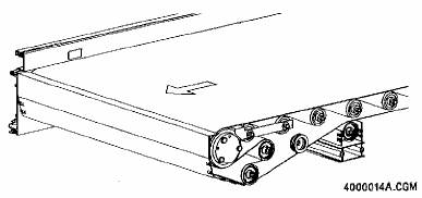
Characteristic |
| Description |
| |
|
|
|
| |
Operating position |
| Horizontal, Incline (0° - 20°), or Decline (0° - 20°) |
| |
|
|
|
| |
Operating mode |
| Transportation |
| |
|
|
|
| |
Operating speed |
| 3.0 m/s |
| |
|
|
|
| |
Physical bed length |
| .75 m to 6 m in .25 m increments |
| |
|
|
|
| |
Physical zone configuration |
| Operates as one zone |
| |
|
|
|
| |
Physical controls location |
| Left or right side channel |
| |
|
|
|
| |
Powered roller |
| 110 mm powered roller |
| |
|
| One per section located at the discharge end of the section |
| |
|
|
|
| |
Idler roller |
| 50 mm with stub axle bearing cartridge |
| |
|
| Quantity varies by bed length |
| |
|
|
|
| |
End pulley roller |
| 55 mm with through axle with high load bearings |
| |
|
| Three located at each end of the section |
| |
|
|
|
| |
Belt |
| Single ply belt including scrim |
| |
|
| Top side of the belt: longitudinal ribs for incline/decline applications |
| |
|
| Top side of the belt: needle fabric/fleece for horizontal applications |
| |
|
| Bottom side of the belt: needle fabric/fleece for all applications |
| |
|
| Splicing: finger splice for production, spiral lacing for replacement belts |
| |
|
|
|
| |
Minimum package requirements |
| Width | 75 mm (dimension perpendicular to flow) |
|
|
| Length | 150 mm (dimension parallel to flow) |
|
|
| Height | 5 mm |
|
|
| Weight | 0.1 kg |
|
|
|
|
|
|
Maximum package dimensions |
| Width | 800 mm (dimension perpendicular to flow) |
|
|
| Length | 1350 mm (dimension parallel to flow) |
|
|
| Height | 800 mm |
|
|
| Weight | 50 kg |
|
Rev 2004-September-20
57
Dematic C-L100-CS Segmented Belt on Roller

In a Dematic C-L100-CS Segmented Belt on Roller (SBOR) section, each zone has one belt. The belt is driven by a 50 mm tapered powered roller and suspended on 50 mm tapered idler rollers.
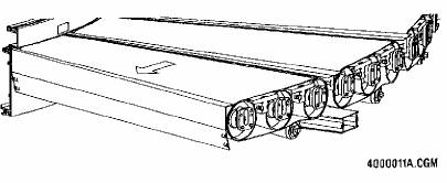
Characteristic |
| Description | ||
|
|
| ||
Operating position |
| Horizontal | ||
|
|
| ||
Operating mode |
| Transportation, Zero Pressure Accumulation | ||
|
|
| ||
Operating speed |
| 0.35 m/s - 2.4 m/s | ||
|
|
| ||
Physical curve direction |
| Left or Right | ||
|
|
| ||
Physical curve angle |
| 30°, 45°, 60°, or 90° (inside radius = 750 mm) | ||
|
|
| ||
Physical zone configuration |
| 30° curve angle = 2 zones, 45° curve angle = 3 zone, | ||
|
| 60° curve angle = 4 zones, 90° curve angle = 6 zones | ||
|
| Each zone requires one powered roller | ||
|
|
| ||
Physical controls location |
| Outer side channel | ||
|
|
| ||
Powered roller |
| 50 mm tapered with high-load bearing cartridge | ||
|
| One per zone located at discharge end of zone | ||
|
|
| ||
Idler roller |
| 50 mm tapered with stub axle bearing cartridge | ||
|
| One per zone located at discharge end of zone | ||
|
|
| ||
Belt |
| 1.7 mm thick PVC belt | ||
|
|
| ||
Minimum package requirements |
| Width |
| 75 mm (dimension perpendicular to flow) |
|
| Length |
| 150 mm (dimension parallel to flow) |
|
| Height |
| 5 mm |
|
| Weight |
| 0.1 kg |
|
|
|
|
|
Maximum package dimensions |
| Width |
| 800 mm (dimension perpendicular to flow) |
|
| Length |
| 1350 mm (dimension parallel to flow) |
|
| Height |
| 800 mm |
|
| Weight |
| 50 kg |
Rev 2004-August-17
58
Dematic C-L100-ST O-ring Drive Roller

In a Dematic C-L100-ST O-ring Drive Roller (ODR) section, each zone has one 50 mm powered roller that drives all the idler rollers in the zone via interleaved o-rings.
Characteristic |
| Description | ||
|
|
| ||
Operating position |
| Horizontal | ||
|
|
| ||
Operating mode |
| Transportation, Zero Pressure Accumulation, Reverse Slug Accumulation | ||
|
|
| ||
Operating speed |
| 0.35 m/s - 1.0 m/s | ||
|
|
| ||
Physical bed length |
| .5 m to 6 m in based on zone length | ||
|
|
| ||
Physical zone configuration |
| .5 m, .75 m, and 1 m zones | ||
|
|
| ||
Physical controls location |
| Left or right side channel | ||
|
|
| ||
Powered roller |
| 50 mm double-grooved with high-load bearing cartridge | ||
|
| One per zone located at the center of the zone | ||
|
|
| ||
Idler roller |
| 50 mm double-grooved with stub axle bearing cartridge | ||
|
| Quantity varies by zone configuration | ||
|
|
| ||
O-ring |
| Polyurethane belt, 4.75 mm thick, 62.5 mm pitch | ||
|
|
| ||
Minimum package requirements |
| Width |
| 75 mm (dimension perpendicular to flow) |
|
| Length |
| 190 mm (dimension parallel to flow) |
|
| Height |
| 5 mm |
|
| Weight |
| 0.1 kg |
|
|
|
|
|
Maximum package dimensions |
| Width |
| 800 mm (dimension perpendicular to flow) |
|
| Length |
| 1350 mm (dimension parallel to flow) |
|
| Height |
| 800 mm |
|
| Weight |
| 30 kg |
Rev 2004-September-20
59
Dematic C-L100-CS O-ring Drive Roller

In a Dematic C-L100-CS O-ring Drive Roller (ODR) section, each zone has one 50 mm powered roller that drives all the idler rollers in the zone via interleaved o-rings.
Characteristic |
| Description | ||
|
|
| ||
Operating Position |
| Horizontal | ||
|
|
| ||
Operating Mode |
| Transportation, Zero Pressure Accumulation, Zero Gap Accumulation | ||
|
|
| ||
Operating Speed |
| 0.35 m/s - 1.0 m/s | ||
|
|
| ||
Physical Curve Direction |
| Left or Right | ||
|
|
| ||
Physical Curve Angle |
| 30°, 45°, 60°, or 90° (inside radius = 750 mm) | ||
|
|
| ||
Physical Zone Configuration |
| 30° curve angle = 2 zones, 45° curve angle = 3 zones, | ||
|
| 60° curve angle = 4 zones, 90° curve angle = 6 zones | ||
|
| Each zone requires one powered roller | ||
|
|
| ||
Physical Controls Location |
| Outer side channel | ||
|
|
| ||
Powered Roller |
| 50 mm double-grooved and tapered with high-load bearing cartridge | ||
|
| One per zone located at the center of the zone | ||
|
|
| ||
Idler Rollers |
| 50 mm double-grooved and tapered with stub axle bearing cartridge | ||
|
| Quantity varies by zone configuration | ||
|
|
| ||
O-ring |
| Polyurethane belt, 4.75 mm thick, 72.5 mm pitch | ||
|
|
| ||
Minimum package requirements |
| Width |
| 75 mm (dimension perpendicular to flow) |
|
| Length |
| 190 mm (dimension parallel to flow) |
|
| Height |
| 5 mm |
|
| Weight |
| 0.1 kg |
|
|
|
|
|
Maximum package dimensions |
| Width |
| 800 mm (dimension perpendicular to flow) |
|
| Length |
| 1350 mm (dimension parallel to flow) |
|
| Height |
| 800 mm |
|
| Weight |
| 30 kg |
Rev 2004-August-17
60
Dematic C-L100-RT Right Angle Transfer

The Dematic C-L100-RT Right Angle Transfer section provides perpendicular package transfers to the left or right in low throughput applications. The RT is available in light and heavy duty configurations.
Characteristic |
| Description |
|
|
|
Operating position |
| Horizontal |
|
|
|
Operating speed |
| 2.4 m/s (maximum) |
|
|
|
Operating raise/lower cycle time |
| 194 msec |
|
|
|
Operating throughput per hour |
| 1800 u/h (maximum) |
|
| Based on a standard 600 mm by 400 mm by 37.5 kg carton |
Operating throughput per minute |
| 30 cpm (maximum) |
|
| Based on a standard 600 mm by 400 mm by 37.5 kg carton |
|
|
|
Operating destinations served |
| Maximum of 3 (straight forward, 90° right, and 90° left) |
|
|
|
Physical bed length |
| 1 m |
|
|
|
Physical zone configuration |
| Operates as one zone |
|
|
|
Physical controls location |
|
|
|
|
|
|
| A master control section must be connected to either Port 2 or 3. |
|
|
|
Powered roller |
| 50 mm powered roller with high-load bearing cartridge |
|
|
|
|
| 2 for light duty configuration, 4 for heavy duty configuration |
|
|
|
Idler roller |
| 41 mm idler rollers |
|
|
|
Drive and transfer belt |
| Flat urethane |
61
Minimum package requirements |
| Width |
| 75 mm (dimension perpendicular to flow) |
|
| Length |
| 190 mm (dimension parallel to flow) |
|
| Height |
| 5 mm |
|
| Weight |
| 0.1 kg |
|
|
|
|
|
Maximum package dimensions |
| Width |
| 800 mm (dimension perpendicular to flow) |
|
| Length |
| 800 mm (dimension parallel to flow) |
|
| Height |
| 800 mm |
|
| Weight |
| 50 kg |
Rev 2004-November-16
62
C-L200 BOR Description
· Fully compatible with Dematic C-L100
· Single drive for long runs
· Extruded aluminum side channels
· Widely varying product loads
· Excellent for inclines
C-L200 BOR belt conveyor complements C-L100 and offers the efficiency of a single drive for long belt conveyor runs. It provides a cost-effective option to motorized rollers
Characteristic |
| Description |
|
|
|
Operation |
| Two-way, horizontal or incline, no accumulation |
|
|
|
Maximum incline/decline |
| 20 degrees, with applicable brake motor |
|
|
|
Maximum product width |
| 820 mm (32") |
|
|
|
Minimum product length |
| 250 mm (10") |
|
|
|
Capacity |
| 65 kg/m (45 lb/ft); 50 kg (110 lb) product maximum |
|
|
|
Speeds |
| .20 m/s – 1.27 m/s in approx. .05 m/s increments (40-250 fpm in approx. 10 fpm increments) |
|
|
|
Temperature Range |
| +2°C to +40°C (+35°F to +104°F) |
|
|
|
Drives |
| 522 lb. center drive |
|
|
|
Motor and Reducer |
| .37 kW through 3.73 kW (1/2 through 5 hp), C-face |
|
|
|
Belt |
| FS x FS (horizontal), RT x FS (inclines) |
|
|
|
Bed |
| Extruded aluminum side channels with extruded crossmembers |
|
| · C-L200 BOR EB: End bed |
|
| · C-L200 BOR IB: Intermediate bed |
|
| · C-L200 BOR DB: Drive bed |
|
|
|
Bed Lengths |
| 500 mm (20"), 750 mm (29"), 1000 mm (39"), 1500 mm (59"), 2000 mm (79"), 2250 mm (89"), 3000 mm (118"), 4500 mm (177"), 6000 mm (236") |
|
|
|
Return Rollers |
| 50 mm (1.97") dia. galvanized with 11 mm (7/16") hex HQ bearings |
|
|
|
Snubber Rollers |
| 56 mm (2-3/16") diameter with HQ bearings |
|
|
|
Carrier Rollers |
| 50 mm (1.97") dia. galvanized with 11 mm (7/16") hex HQ bearings |
|
|
|
Roller Centers |
| 125 mm (5") or 187.5 mm (7-3/8") |
|
|
|
End Pulley |
| 100 mm (4") diameter with 37 mm (1-7/16") diameter fixed shaft |
|
|
|
Power Feeder |
| C-L200 PT, box bed with 100 mm (4") diameter end and drive pulleys |
|
|
|
Noseover Hinge |
| C-L200 NO, with two T-bars and two 56 mm (2-3/16") snubber rollers |
Rev 2006-June 1
63
C-L200 BOS Description
· Fully compatible with Dematic C-L100
· Single drive for long runs
· Extruded aluminum side channels
· Widely varying product loads
· Excellent for declines
C-L200 BOS conveyor complements C-L100, offers the efficiency of a single drive for long runs, and provides a cost-effective option to motorized rollers.
Characteristic |
| Description |
|
|
|
Operation |
| Two-way, horizontal or incline, no accumulation |
|
|
|
Maximum incline/decline |
| 20 degrees, with applicable brake motor |
|
|
|
Maximum product width |
| 820 mm (32") |
|
|
|
Minimum product length |
| None |
|
|
|
Capacity |
| 65 kg/m (45 lb/ft); 50 kg (110 lb) product maximum |
|
|
|
Speeds |
| .20 m/s – 1.27 m/s in approx. .05 m/s increments (40-250 fpm in approx. |
|
| 10 fpm increments) |
|
|
|
Temperature Range |
| +2°C to +40°C (+35°F to +104°F) |
|
|
|
Drive |
| 522 lb. center drive |
|
|
|
Motor and Reducer |
| .37 kW through 3.73 kW (1/2 through 5 hp), C-face |
|
|
|
Belt |
| FS x FS (horizontal), RT x FS (inclines) |
|
|
|
Bed |
| 10-gage steel pan and extruded crossmembers bolted between extruded aluminum side channels. Available bed heights of 179 mm (7') (standard) or 173 mm (6-13/16") (merge points) |
|
| · C-L200 BOS EB: End bed |
|
| · C-L200 BOS IB: Intermediate bed |
|
| · C-L200 BOS DB: Drive bed |
|
|
|
Bed Lengths |
| 500 mm (20"), 750 mm (29"), 1000 mm (39"), 1500 mm (59"), 2000 mm (79"), 2250 mm (89"), 3000 mm (118"), 4500 mm (177"), 6000 mm (236") |
|
|
|
Return Rollers |
| 50 mm (1.97") dia. galvanized with 11mm (7/16") hex HQ bearings |
|
|
|
Snubber Rollers |
| 56 mm (2-3/16") diameter with HQ bearings |
|
|
|
End Pulley |
| 100 mm (4") diameter with 37 mm (1-7/16") diameter fixed shaft |
|
|
|
Power Feeder |
| C-L200 PT, box bed with 100 mm (4") dia. end and drive pulleys |
|
|
|
Noseover Hinge |
| C-L200 NO, with two T-bars and two 56 mm (2-3/16") snubber rollers |
|
|
|
Roller Box Bed |
| Rollers spaced under the belt for reduced suction and friction |
Rev 2006-June 1
64
C-L200 RA Description
· Fully compatible with Dematic C-L100
· Single drive for long runs
· Extruded aluminum side channels
· Zero line pressure
· Quiet at low and high speeds
C-L200 RA Roller Accumulation Conveyor complements C-L100 and offers the efficiency of using a single drive for long conveyor runs. It provides a cost-effective option to motorized rollers.
Characteristic |
| Description |
|
|
|
Operation |
| One-way, horizontal, accumulation |
|
|
|
Accumulation |
| Zero line pressure accumulation with electronic sensing |
|
|
|
Maximum product width |
| 900mm (35") |
|
|
|
Minimum product length |
| None |
|
|
|
Capacity |
| 65 kg/m (45 lb/ft); 50 kg (110 lb) product maximum |
|
|
|
Speeds |
| .25 m/s — 2 m/s in approx. 05 m/s increments (50-400 fpm in approx. 10 fpm increments) |
|
|
|
Discharge Rates (3” roller centers) |
| With no reflector offset, at .85 m/s (168 fpm): |
|
| · 50% w/ singulation discharge |
|
| · 90% w/ dynamic accumulation |
|
| With 152 mm (6") reflector offset: 65% w/ dynamic accumulation |
|
|
|
Operating Temperature Range |
| +2°C to +40°C (+35°F to +104°F); 5% to 95% relative non-condensing |
|
| humidity |
|
|
|
Drives |
| C-L200 RA DR Drive Assembly |
|
| Standard: End drive with 158 kg (350 lb) maximum pull, with 1.1m |
|
| (44") belt take-up |
|
| Center drive available for when more clearance is needed under charge end |
|
|
|
Motor and Reducer |
| Totally enclosed .75 kW to 3.73 kW (1 to 5 hp) C-face motor and 90° |
|
| shaft gear reducer |
|
|
|
Drive Belt |
| Flat polyurethane body with aramid fiber reinforcement and anti-static |
|
| nylon back |
|
|
|
Bed |
| Extruded aluminum 175mm (7") deep side channels, bolted construction |
|
| · C-L200 RA EB: End bed |
|
| · C-L200 RA IB: Intermediate bed |
|
| · C-L200 RA DB: Drive bed |
65
C-L200 RA Description
Skewed Roller Bed |
| C-L200 RA SB: Provides 51 mm or 76 mm (2" or 3") skew for edge |
|
| alignment of products to a specific side. Available with 3.66 m (12') |
|
| long beds only |
|
|
|
Bed Lengths |
| Intermediate: 1.52 m (5'), 1.83 m (6'), 2.13 m (7'), 3.05 m (10'), 3.66 m |
|
| (12'), 4.57 m (15'), 5.49 m (18') |
|
| Charge: 3.66 m (12') |
|
| Discharge: 1.83 m (6') and 3.66 m (12') |
|
|
|
Carrier Rollers |
| 50mm (1.97") dia. galvanized steel captured rollers with 11 mm (7/16") |
|
| hex HQ bearings, 76 mm (3") centers |
|
|
|
Sensor Assembly |
| Photoeye and matching reflector fit in the guide channels |
|
|
|
Drive Pulley |
| Solid Steel in 134 mm (5-9/32") to 167 mm (6-9/16") diameter, depending on speed |
|
|
|
End Pulley |
| 140 mm (5-1/2") diameter at charge and discharge ends |
|
|
|
Controlled End Cap and Intermediate |
| Engages / disengages drive in the zone on a charge / discharge bed. |
|
|
|
Bed Assembly for Controlled Charge |
| Also available with a brake that stops rotation of carrier rollers near |
and Discharge |
| end of discharge bed |
|
|
|
Slug Discharge (via electrical signal) |
| Activates selected or all zones to live roller mode |
|
|
|
Photoeye |
| Up to 100 ma, 30 VDC |
|
| 120 VAC and 24 VDC output |
|
|
|
ES Valve and Control Assy |
| 21-28 VDC at 40 to 80 ma DC, sleep mode |
|
|
|
Solenoid Air Valve (End Assy w/o or |
| 3- or 4-way, 120 VAC and 24 VDC. |
w/brake) |
|
|
|
|
|
Slug Discharge and Dynamic |
| Optional valve kits available in 120 VAC and 24 VDC. |
Accumulation |
|
|
|
|
|
Air operating pressure |
| 3.16 kg/cm (45-psi) Recommended minimum for air source: 4.92 kg/cm (70-psi) |
|
|
|
Belt Take-up pressure |
| 3.16 kg/cm (45-psi) |
|
|
|
Control air pressure |
| .49 kg/cm (7 psi) |
Rev 2006-June 1
66
Model 0100 Gravity Wheel Conveyor
· High Strength-To-Weight Ratio
· Wide Wheel Face
· Hardened Raceways
Light and portable gravity wheel conveyors are the first choice for materials with a reasonably firm bottom surface and moderate weight.
10' Bed Capacities (pounds)
|
| Steel Frame |
| Aluminum Frame |
| ||||
|
| 2-1/2" |
| 4" |
| 2-1/2" |
| 2-1/2" |
|
Width |
|
|
| Steel |
| Aluminum |
| ||
(in.) |
| Steel Wheels |
| Wheels |
| Wheels |
| ||
12 |
| 730 |
| 1165 |
| 475 |
| 485 |
|
18 |
| 705 |
| 1145 |
| 460 |
| 470 |
|
24 |
| 680 |
| 1120 |
| 440 |
| 460 |
|
One Wheel |
| 25 |
|
|
|
|
| 12 |
|
Axle Centers: 3 inches.
Wheels Per Foot: Other wheel patterns than shown are available.
Standard Wheels per Foot
Width |
| 3" c-c |
| 1-1/2" c-c |
|
12" |
| 10 and 12 |
| 24 |
|
18" |
| 16 and 18 |
| 36 |
|
24" |
| 20 and 24 |
| 48 |
|
Steel Beds: 12 gage, 2-1/2” deep, galvanized, bolted-in crossmembers.
Aluminum Beds: 1/8" thick, 2-1/2" deep, bolted-in crossmembers.
Wheels: Steel or aluminum, 1-15/16" diameter, 5/8" wide face and 1/4" diameter axle. Greased steel bearings. Baffle cone construction keeps grease in and dirt out.
Weights per Foot (pounds)*
Description |
| Widths (in.) |
| ||||
Frame-Wheels |
| 12 |
| 18 |
| 24 |
|
Steel - Steel |
| 10.3 |
| 11.9 |
| 15.0 |
|
Alum - Steel |
| 8.3 |
| 9.8 |
| 12.7 |
|
Alum - Alum |
| 7.2 |
| 8.2 |
| 9.9 |
|
* Weights include 3 lb/ft for supports.
Bed Lengths: 5' and 10'. Also available in 1'-12' lengths in 3" increments.
Curve Degrees: 45 and 90.
Connectors: Straight section has hooks on one end and bar at other end.
67
Rev 2005-March-11
Curve Capacities: All curve capacities are equal to or in excess of corresponding 10’ straight sections.
90 Degree Curve Weights (pounds)**
Description |
| Widths (in.) |
| ||||
Frame - Wheels |
| 12 |
| 18 |
| 24 |
|
Steel - Aluminum (lb) |
| 104 |
| 110 |
| 121 |
|
Aluminum - Steel (lb) |
| 91 |
| 97 |
| 104 |
|
Aluminum - Aluminum (lb) |
| 84 |
| 86 |
| 93 |
|
** Weights include 60 Ib/curve for supports.
Options
Wheels Low: With 4" deep steel frame.
Axle Centers: 1-1/2"
Wheels: Wheels with oiled or dry bearings. Nylon wheels (capacity 6 lb), PVC coating, black or non-marking gray neoprene tires. PVC coating and tires are used only on the outer third of curves and cannot be used with 1-1/2" axle centers.
Connectors: Hooks and bars at both ends.
Normal Width |
| Radius Feet |
| Degree |
| W (in.) Width |
| A (in.) Outer |
| B (in.) Inner |
|
12 |
| 3 |
| 45 |
|
|
| 37 |
| 25, 36-1/2, 48-1/2, 60-1/2 |
|
12 |
| 4 |
| and |
| 11-15/16 |
| 48-1/2 |
|
|
|
18 |
| 5 |
| 90 |
| 17-15/16 |
| 60-1/2 |
| 30-1/2, 42-1/2, 54-1/2 |
|
24 |
| 6 |
|
|
| 23-15/16 |
| 72-1/2 |
| 24-1/2, 36-1/2, 48-1/2 |
|
Rev 2005-March-11
68
Model 0200 Gravity Roller Conveyor 1.9 Hex
· Five Widths
· Single/Double Lane Curves
· 45 and 90 Degree Curves
Gravity conveyor mechanizes an operation that doesn’t justify powered equipment. Gravity conveyor quickly and effortlessly moves thousands of items in almost any direction with minimal operating and maintenance costs.
Bed: 10 gage, 3-1/2" deep, galvanized, welded construction. 5' and 10' long. Other lengths available.
Curves: Single and double lane. Double lane is not available in 12" and 18" widths. 45 and 90 degrees.
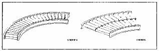
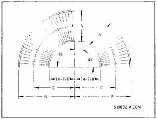
Straight and Curve Dimensions
A (Overall Width) (in.) |
| C (in.) |
| B(in.) |
12-1/4 |
| 41 |
| 47-1/8 |
18-1/4 |
| 44 |
| 53-1/8 |
24-1/4 |
| 47 |
| 59-1/8 |
30-1/4 |
| 50 |
| 65-1/8 |
36-1/4 |
| 53 |
| 71-1/8 |
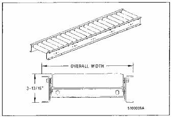
10 Foot Bed Capacities (pounds)
Width (in.) |
| Roller Centers |
| ||
|
| 3" c-c |
| 4" c-c |
|
12 |
| 1260 |
| 1280 |
|
18 |
| 1225 |
| 1250 |
|
24 |
| 1185 |
| 1220 |
|
30 |
| 1145 |
| 1190 |
|
36 |
| 1105 |
| 1160 |
|
One Roller |
|
|
| 250 |
|
NOTE 5-foot sections are at least twice the capacity amount of a 10-foot section (subject to the capacity of the rollers supporting the load).
Rollers: 16-gage galvanized, 7/16” hex SR bearings, and 3” and 4” roller centers.
Curve Capacities: Equal to or in excess of 10’ straight sections.
Weights per Foot (pounds) with SR Bearings*
Roller |
| Widths (in.) |
| ||||||||
Centers |
| 12" |
| 18" |
| 24" |
| 30" |
| 36" |
|
3" c-c |
| 15.6 |
| 19.6 |
| 23.9 |
| 27.6 |
| 31.7 |
|
4" c-c |
| 13.8 |
| 16.9 |
| 20.4 |
| 23.3 |
| 26.5 |
|
* Weights include 3 lb/ft for supports.
Options: Rollers Low, 14 gage, and 2-1/4" centers.
Optional Widths: 42" through 54" in 6" increments.
90 Degree Curve Weights (pounds)**
Width |
| 12" |
| 18" |
| 24" |
| 30" |
| 36" |
|
Weight |
| 140 |
| 174 |
| 205 |
| 239 |
| 269 |
|
** Weights include 60 lb/curve for supports.
Rev 2005-March-12
69
Model 0405 Slider Bed Conveyor
· Rugged
· Versatile
· Wide Range of Widths
· E-Z Trac® Pulleys
Model 0405 Slider Bed conveyor is an economical choice for widely varying load sizes and shapes. In addition to mixed loads, slider beds can handle hard-to-convey products such as crates, bags, bundles, rolls, and unpackaged goods.
Operation: Two-way, horizontal, incline, or decline. No accumulation.
Capacity: 158 lb/ft max. with 12-1/4" wide bed.
Speeds: 40-200 fpm fixed in 10-fpm increments.
Drives: 500 lb series drives (520 lb and 522 lb pull center drives) with 8" diameter pulley on a 2-7/16" diameter shaft with 1-3/16" diameter bearings and input (520) or 1-7/16" bearings & 1-3/16" input (522). Chain final drive (520) or cog belt final drive (522). 1050 lb pull center drive with 12" diameter pulley on 2-7/16" diameter shaft with 1-15/16" diameter bearings and input.
For each drive, pulley has molded-on, flat lagging, and self-aligning bearings in which the shaft mounts.
Take-up in Drives: 4" diameter (6" for 1050) E-Z Trac belt take-up pulley with lifetime grease packed, sealed ball bearings mounted to a 1-7/16" diameter (1-15/16" for 1050) fixed shaft.
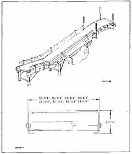
Take-up Pulley: Mounts on parallel take-up screws; adjusts manually. Maximum belt take-up:
· 26" with 520 lb (Center Drive)
· 16" with 522 lb (Center Drive)
· 24-1/2" with 1050 lb and 2050 lb Center and End Drive
Product Specifications
Drive |
| A |
| B |
520 lb |
| 14" |
| 54" |
522 lb |
| 17" |
| 59" |
1050 lb |
| 27" |
| 65" |
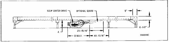
70
Rev 2006 February-02
Belt: PVC-impregnated polyester carcass. With horizontal, both sides low-friction surfaces. With incline/meter/brake, low-friction on bottom, rough top. Belt width is 4" less than bed width of 30" through 54".
Bed: Painted, 12-gage steel, 5-1/4" deep box type, bolted-in crossmembers.
Motor and Reducer: 1/3 through 7-1/2 hp, C-face. Brake motor on incline/decline units.
Bed Lengths: 12'. Other lengths available.
End Pulley: 4" diameter with 1-7/16" diameter fixed shaft or 6" diameter pulley with 1-15/16" diameter fixed shaft. Has precision, grease-packed ball bearings mounted in machined bores, spin formed into the ends of the pulley shell.
Return Rollers: 1.9" diameter, 16 gage, galvanized steel with 7/16" hex SR bearings.
Nose-over: Painted, 10 gage, one piece laser cut side channels, 5-1/4" deep with 2-3/16" diameter, 12-gage carrier rollers.
Power Feeder: Box type bed with 4" or 6" diameter end pulleys. A 4" or 6" diameter main line end pulley drives power feeder end pulley by chain and sprockets.
Product Specifications (Dimension A)
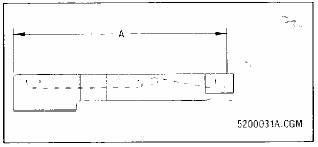
A
Drive |
| Widths (Nominal) |
| ||||||||||
|
| 12" |
| 18-24" |
| 30 " |
| 36 " |
| 42 " |
| 48-54 " |
|
4" |
| 3'7-1/8" |
| 4'1-1/8" |
| 5'7-1/8" |
| 6'7-1/8" |
| 9'1-1/8" |
| — |
|
6" |
| — |
| 4'2" |
| 5'8" |
| 6'8" |
| 9'2" |
| 9'4-1/16" |
|
Accessories
Gravity Wheel Feeder
Slave Drive: Model 0996 curves and junctions.
Auxiliary Horizontal Take-up: 4” diameter pulleys provide 24” or 48” of belt take-up.
Options
Speeds: Higher speeds available.
522 lb Center Drive: With chain final drive.
Beds: Galvanized roller slider has 1.9" diameter rollers projecting 7/16" above the top surface of bed, with roller centers varying from 14" to 30". Available with single or double lanes. Wheel slider also available.
Conveyor and Drive Weights: Ask your Sales Engineer for weight information.
End Pulley (underslung):
· 260 lb: 4" dia. drive pulley, 1-7/16" dia. shaft.
· 520 lb: 8" dia. drive pulley, 2-7/16" dia. shaft.
· 1050 lb: 12" dia. drive pulley, 1-15/16" dia. shaft.
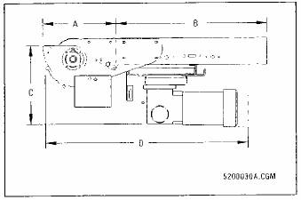
Product Specifications
Drive |
| A (in.) |
| B |
| C(in.) |
| D (in.) |
|
260 lb |
| 7-1/16 |
| * |
| 19-3/4 |
| 44 |
|
520 lb |
| 15-1/2 |
| * |
| 19-7/8 |
| 57 |
|
1050 lb |
| 48-1/2 |
| — |
| 25 |
| 69 |
|
* 2-1/2’ or 10’ Bed
Rev 2006 February-02
71
Model 0410 Belt-on-Roller Conveyor
· Rugged
· Versatile
· Wide Range of Widths .
· E-Z Trac® Pulleys
This belt-on-roller conveyor allows handling loose and irregular-shaped products and relatively heavy loads over a long distance.
Operation: Two-way, horizontal, incline, or decline. No accumulation.
Capacity: 141-lb/ft max. with 12-1/4" wide bed.
Speeds: 40-200 fpm fixed in 10-fpm increments.
Drives: 522 lb pull center drive with 8" diameter pulley on a 2-7/16" diameter shaft with 1-7/16" diameter bearings and 1-3/16" input for cog belt final drive. 1050 lb pull center drive with 12" diameter pulley on 2-7/16" diameter shaft with 1-15/16" diameter bearings and input.
Pulleys have molded-on, flat lagging, and self-aligning bearings in which the shaft mounts.
Take-up in Drives: 4" diameter (6" for 1050) E-Z Trac belt take-up pulley with lifetime grease packed, sealed ball bearings mounted to a 1-7/16” diameter (1-15/16" for 1050) fixed shaft.
Take-up pulley mounts on parallel take-up screws and adjusts manually for maximum take-up of 16" (522 lb) or 24-1/2" (1050 lb).
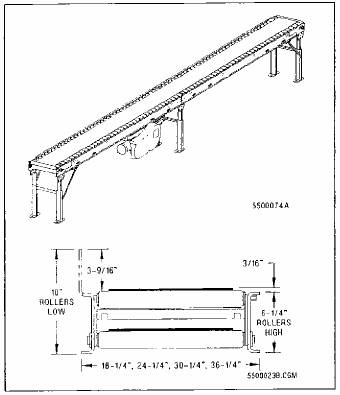
Belt: PVC-impregnated polyester carcass. With horizontal, both sides low-friction surfaces. With incline/meter/brake, low-friction on bottom, rough top. Belt width is 4" less than bed width for 12" through 24" and 6" less for 30" through 54".
Bed: Painted, 10-gage steel, 6-1/4" deep, 1-1/8" flanges, bolted construction.
Bed Lengths: 12. Other lengths available.
Product Specifications
Drive |
| A |
| B |
|
522 lb |
| 17" |
| 59" |
|
1050 lb |
| 27" |
| 65" |
|
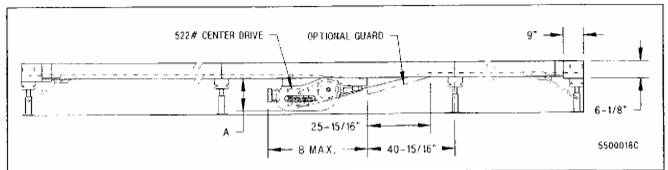
Rev 2006 March-11
72
Motor and Reducer: 1/3 through 10 hp, C-face, 1750 rpm. Brake motor on incline/decline units.
End Pulley: 4” diameter with 1-7/16” diameter fixed shaft or 6” diameter pulley with 1-15/16” diameter fixed shaft. Has precision, grease-packed ball bearings mounted in ends of the pulley shell.
Rollers: 1.9” diameter, 16-gage, galvanized steel with 7/16” hex SR bearings. Captured rollers high.
Roller Centers: 4” or 8”.
Nose-over: Painted, 10-gage, one piece laser cut side channels, 6-1/4” deep with 2-3/16” diameter, 12-gage carrier rollers.
Power Feeder: Box type bed with 4” or 6” diameter end pulleys. A 4” or 6” diameter main line end pulley drives power feeder end pulley by chain and sprockets.
Product Specifications (Dimension A)
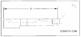
A
Drive Pulley Dia |
| Widths (Nominal) |
| ||||||||||
|
| 12" |
| 18-24" |
| 30" |
| 36" |
| 42" |
| 48-54" |
|
4" |
| 3'7-1/8" |
| 4'1-1/8" |
| 5'7-1/8" |
| 6'7-1/8" |
| 9’1-1/8" |
| — |
|
6" |
| — |
| 4'2" |
| 5'8" |
| 6’8" |
| 9'2" |
| 9'4-1/16" |
|
Accessories
Gravity Wheel Feeder
Slave Drive: Model 996 curves and junctions.
Auxiliary Horizontal Take-up: 4” diameter pulleys provide 24” or 48” of belt take-up.
Options
Speeds: Other speeds available.
522 lb Center Drive: With chain final drive.
Rollers: 14-gage, high speed HQ bearings for extended conveyor life with reduced noise, and captured rollers low.
End Pulley: With 4" of take-up (8" of belt).
Widths: 12-1/4", 42-1/4", 48-1/4", and 54-1/4".
Conveyor and Drive Weights: Ask your Sales Engineer for weight information.
End Pulley (underslung):
· 260 lb: 4" dia. drive pulley, 1-7/16" dia. shaft.
· 520 lb: 8" dia. drive pulley, 2-7/16" dia. shaft.
· 1050 lb: 12" dia. drive pulley, 1-15/16" dia. shaft.
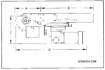
Drive |
| A (in.) |
| B |
| C (in.) |
| D (in.) |
|
260 lb |
| 7-1/1 | 6 | * |
| 19-3/ | 4 | 44 |
|
520 lb |
| 15-1/ | 2 | * |
| 19-7/ | 8 | 57 |
|
1050 lb |
| 48-1/ | 2 | — |
| 25 |
| 69 |
|
* 2-1/2’ or 10’ Bed
73
Model 0460 Empty Carton Conveyor
· Reliable
· Economical
· E-Z Trac® Pulleys
This empty carton conveyor handles empty scrap cartons, packing and wrapping materials, etc.
Operation: Two-way, horizontal, incline or decline up to 20 degrees. No accumulation.
Capacity: 5 lb/ft.
Speeds: 40-90 fpm fixed in 10-fpm increments.
Drives: 522 lb pull center drive with 8" diameter pulley on a 2-7/16" diameter shaft with 1-7/16" bearings and 1-3/16" input for cog belt final drive. 1050 lb pull center drive with 12" diameter pulley on 2-7/16" diameter shaft with 1-15/16" diameter bearings and input.
End Pulley: 4” diameter on 1-7/16” diameter shaft, with or less shroud with precision bearings.
Motor and Reducer: 1/2 through 2 hp, C-face.
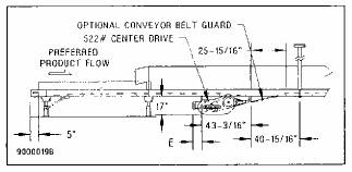
E (max. in.) Motor Length Less Brake
Reducer |
| Incline 0°-14° |
| Incline 15°-25° |
|
175 |
| 8-5/8 |
| 11-13/16 |
|
200 |
| 7-5/8 |
| 10-5/16 |
|
262 |
| 12-1/2 |
| 15-5/16 |
|
350 |
| 13-5/8 |
| 16-5/8 |
|
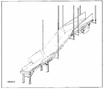
Bottom Dust Covers: 18 gage galvanized steel with stiffeners and 1/4” gap between covers:
Roller with Standard Dust Covers (with side guards shown)
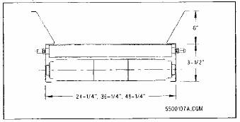
Roller with Full Dust Covers (side guards not shown)
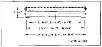
74
Bed: 36" and 48" wide, galvanized, 14-gage steel, 3-1/2"-deep box type, with structural angle stiffeners.
Belt: PVC-impregnated polyester carcass with horizontal, low-friction surfaces on both sides. With incline, low-friction bottom, rough top. Belt width is 6” less than bed width.
Bed Length: 10'. Other lengths are available.
Return Rollers: 1.9" diameter, 16-gage, galvanized steel with 7/16" hex SR bearings.
Side Guards: 6" high, 14 gage, and galvanized steel.
Conveyor Weights (pounds)
Bed Width |
| 24” |
| 36” |
| 48” |
|
Per Foot* |
| 15 |
| 22 |
| 27 |
|
Drive* |
| 346 |
| 402 |
| 460 |
|
*Includes 3 lb/ft for supports.
Options
522 lb Center Drive: With chain final drive.
Beds and Dust Covers: 4-1/8" deep 24" wide bed and full dust covers.
Double Snubber: 5-20 degree incline or decline.
Frame: 12-gage galvanized steel. 4" diameter pulleys, 2-3/16" 12-gage snubber rollers and 18" high side guards.
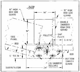
Nose-over: 5-20 degree incline. 3/16" painted side plates, 2-3/16" snubber rollers, and 18" high, 14-gage side guards.
Side Guards: 18" high, 14-gage.
Rev 2005-March-11
75
Model 0977 Flat Belt Turn
· Maintains Product Orientation
· Assures Positive Spacing
· High Speed
· Low Noise
Flat belt turns are used in conveyor systems where product spacing and orientation must be maintained. The curved belt surface also allows odd-shaped and fragile products to be conveyed around bends. The Flat Belt Turn is suitable for high speed, low noise applications (up to 500 fpm with less than 75 dBA noise levels).
Degrees: 30, 45, 60, 90, 180.
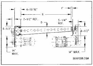
Belt: PVC 100 with smooth top and friction back. Laced belt is standard; endless is optional. Special belts also available.
Bed: Steel bolted and welded frame with steel shrouding. 10 gage inside channel track; 5/16” steel outside track and aluminum brackets.
End Pulleys: Cast aluminum tapered pulleys, precision machined. Drive pulley is lagged with friction material.
Guard Rails: 12 gage painted steel, 6”, 12”, or 18” high as required. Flange guard rail and channel guard rail available upon request.
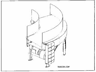
Operation: One-way, horizontal.
Capacity: (Maximum live loads for 90 degree turns).
· Series B: 200 lb live load.
· Series C: 280 lb live load.
· Series D: 360 lb live load.
Speeds: Up to 550 fpm at centerline of belt, fixed, depending on model and degrees.
Drive: Base-mounted 3/4-5 hp gearmotor located at discharge end, preferably on outside of curve. Timing belt connection between gearmotor and drive pulley.
NOTE Shaft mounted drives are available.
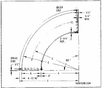
Rev 2005-March-14
76
Replaceable Components: The motor and gearbox are made by Eurodrive, the bearings are made by Dodge, the drive belt and sprockets are made by Dodge (or an equivalent) and the belting is Georgia Duck (or an equivalent). The drive pulleys, end pulleys, take-up components, and return rollers are all custom and will be stocked in reasonable quantities.
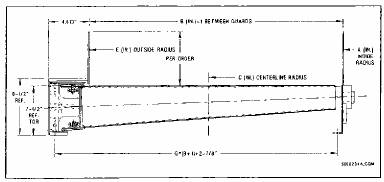
Model No.* |
| Degrees |
| A (in.) |
| B (in.) |
| C (in.) |
| D (in.) |
| E (in.) |
| F (in.) |
| G (in.) |
|
B 59 22 |
| 30,45,60,90,180 |
| 36 |
| 22 |
| 48 |
| 4.79 |
| 59 |
| 63-13/16 |
| 25-7/8 |
|
B 59 24 |
| 30,45,60,90,180 |
| 34 |
| 24 |
| 47 |
| 4.69 |
| 59 |
| 63-13/16 |
| 27-7/8 |
|
B 59 26 |
| 30,45,60,90,180 |
| 32 |
| 26 |
| 46 |
| 4.59 |
| 59 |
| 63-13/16 |
| 29-7/8 |
|
B 59 28 |
| 30,45,60,90,180 |
| 30 |
| 28 |
| 45 |
| 4.49 |
| 59 |
| 63-13/16 |
| 31-7/8 |
|
B 59 30 |
| 30,45,60,90,180 |
| 28 |
| 30 |
| 44 |
| 4.39 |
| 59 |
| 63-13/16 |
| 33-7/8 |
|
B 59 32 |
| 30,45,60,90,180 |
| 26 |
| 32 |
| 43 |
| 4.29 |
| 59 |
| 63-13/16 |
| 35-7/8 |
|
B 59 34 |
| 30,45,60,90,180 |
| 24 |
| 34 |
| 42 |
| 4.19 |
| 59 |
| 63-13/16 |
| 37-7/8 |
|
B 59 36 |
| 30,45,60,90,180 |
| 22 |
| 36 |
| 41 |
| 4.09 |
| 59 |
| 63-13/16 |
| 39-7/8 |
|
C 87 24 |
| 30,45,60,90,180 |
| 62 |
| 24 |
| 75 |
| 5.18 |
| 87 |
| 91-13/16 |
| 27-7/8 |
|
C 87 26 |
| 30,45,60,90,180 |
| 60 |
| 26 |
| 74 |
| 5.11 |
| 87 |
| 91-13/16 |
| 29-7/8 |
|
C 87 28 |
| 30,45,60,90,180 |
| 58 |
| 28 |
| 73 |
| 5.04 |
| 87 |
| 91-13/16 |
| 31-7/8 |
|
C 87 30 |
| 30,45,60,90,180 |
| 56 |
| 30 |
| 72 |
| 4.97 |
| 87 |
| 91-13/16 |
| 33-7/8 |
|
C 87 32 |
| 30,45,60,90,180 |
| 54 |
| 32 |
| 71 |
| 4.90 |
| 87 |
| 91-13/16 |
| 35-7/8 |
|
C 87 34 |
| 30,45,60,90,180 |
| 52 |
| 34 |
| 70 |
| 4.83 |
| 87 |
| 91-13/16 |
| 37-7/8 |
|
C 87 36 |
| 30,45,60,90,180 |
| 50 |
| 36 |
| 69 |
| 4.76 |
| 87 |
| 91-13/16 |
| 39-7/8 |
|
C 87 38 |
| 30,45,60,90,180 |
| 48 |
| 38 |
| 68 |
| 4.69 |
| 87 |
| 91-13/16 |
| 41-7/8 |
|
C 87 40 |
| 30,45,60,90,180 |
| 46 |
| 40 |
| 67 |
| 4.63 |
| 87 |
| 91-13/16 |
| 43-7/8 |
|
C 87 42 |
| 30,45,60,90,180 |
| 44 |
| 42 |
| 66 |
| 4.56 |
| 87 |
| 91-13/16 |
| 45-7/8 |
|
C 87 44 |
| 30,45,60,90,180 |
| 42 |
| 44 |
| 65 |
| 4.49 |
| 87 |
| 91-13/16 |
| 47-7/8 |
|
C 87 46 |
| 30,45,60,90,180 |
| 40 |
| 46 |
| 64 |
| 4.42 |
| 87 |
| 91-13/16 |
| 49-7/8 |
|
C 87 48 |
| 30,45,60,90,180 |
| 38 |
| 48 |
| 63 |
| 4.35 |
| 87 |
| 91-13/16 |
| 51-7/8 |
|
D 115 24 |
| 30,45,60,90,180 |
| 90 |
| 24 |
| 103 |
| 5.44 |
| 115 |
| 119-13/16 |
| 27-7/8 |
|
D 115 26 |
| 30,45,60,90,180 |
| 88 |
| 26 |
| 102 |
| 5.38 |
| 115 |
| 119-13/16 |
| 29-7/8 |
|
D 115 28 |
| 30,45,60,90,180 |
| 86 |
| 28 |
| 101 |
| 5.33 |
| 115 |
| 119-13/16 |
| 31-7/8 |
|
D 115 30 |
| 30,45,60,90,180 |
| 84 |
| 30 |
| 100 |
| 5.28 |
| 115 |
| 119-13/16 |
| 33-7/8 |
|
D 115 32 |
| 30,45,60,90,180 |
| 82 |
| 32 |
| 99 |
| 5.22 |
| 115 |
| 119-13/16 |
| 35-7/8 |
|
D 115 34 |
| 30,45,60,90,180 |
| 80 |
| 34 |
| 98 |
| 5.17 |
| 115 |
| 119-13/16 |
| 37-7/8 |
|
D 115 36 |
| 30,45,60,90,180 |
| 78 |
| 36 |
| 97 |
| 5.12 |
| 115 |
| 119-13/16 |
| 39-7/8 |
|
D 115 38 |
| 30,45,60,90,180 |
| 76 |
| 38 |
| 96 |
| 5.07 |
| 115 |
| 119-13/16 |
| 41-7/8 |
|
D 115 40 |
| 30,45,60,90,180 |
| 74 |
| 40 |
| 95 |
| 5.01 |
| 115 |
| 119-13/16 |
| 43-7/8 |
|
D 115 42 |
| 30,45,60,90,180 |
| 72 |
| 42 |
| 94 |
| 4.96 |
| 115 |
| 119-13/16 |
| 45-7/8 |
|
D 115 44 |
| 30,45,60,90,180 |
| 70 |
| 44 |
| 93 |
| 4.91 |
| 115 |
| 119-13/16 |
| 47-7/8 |
|
D 115 46 |
| 30,45,60,90,180 |
| 68 |
| 46 |
| 92 |
| 4.86 |
| 115 |
| 119-13/16 |
| 49-7/8 |
|
D 115 48 |
| 30,45,60,90,180 |
| 66 |
| 48 |
| 91 |
| 4.80 |
| 115 |
| 119-13/16 |
| 51-7/8 |
|
* For complete model numbers, add “977” to the beginning of this number, and add the appropriate degree (30, 45, 60, 90, or 180) to the end.
Rev 2005-March-14
77
Model 1102 Live Roller Conveyor
· Adjustable Belt Pressure
· Pop-Out Rollers
· E-Z Trac Pulleys
This transportation conveyor can be used for low-pressure accumulation when zero line pressure is not required. Carrier rollers activated from below by a drive belt provide a smooth, low friction-conveying surface. Individually adjustable pressure rollers enable varying drive pressure.
Operation: Two-way with center drive. Horizontal; inclines/declines up to 5 degrees.
Rollers: 1.9” diameter, 16-gage, galvanized steel with 7/16” hex HQ bearings. Pop-out rollers high.
Roller Centers: 3” carrier and 6” pressure centers.
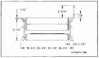
Capacity: 135 lb/ft.
Speeds: 40-200 fpm in 10-fpm increments.
Motor and Reducer: 1/2-5 hp, C-face motor.
Belt: 8” wide, PVC-impregnated polyester carcass with smooth top and bottom.
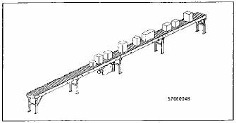
Drive: 522 lb pull center drive with 8” diameter pulley, with lagging, on a 2-7/16” diameter shaft, with 1-7/16” self-aligning pillow block bearings and 1-3/16” input for cog belt final drive. Take-up pulley 4” diameter on 1-7/16” diameter fixed shaft for 16” of belt take-up.
Bed Lengths: 12’ long. Other lengths available.
End Pulley: 4” diameter pulley on 1-7/16” diameter shaft.
Bed: 10-gage, 6-1/4” deep, painted, bolted.
Auxiliary Horizontal Take-Up: Four-inch diameter pulleys provide 24” or 48” of belt take-up.
Options
522 lb Center Drive: With chain final drive.
Rollers: 16-gage, SR bearings, and pop-out and captured rollers low.
Roller Centers: 3”-9”, 3”-12”, 4”-8”, 4”-12”.
Widths: 12-1/4”, 42-1/4”, 48-1/4”, and 54-1/4”.
Accessories
End Drive: 520 lb pull with 8” diameter pulley on 2-7/16” diameter shaft. 34” of belt take-up.
Slave Drive: Model 996 curves and junctions.
Case Stop: Air, foot, hand or motor operated.
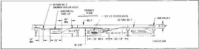
Rev 2005-April-29
78
^+
Model 2310 Single Line Dual Servo Induction
· Four Variable Speed Belts Per Line
· Dual Servo Control
The Single Line Induct (SLI) allows low speed, economical conveyor to feed a high-speed sorter with the required spacing. The dual servo SLI operates with the RS200 PLUS sorter.
The packages enter the induction belt section. Each dual belt section has variable speed belts mechanically coupled to maintain a constant speed ratio between belts. This induct unit is designed for 20 lb/ft live load.
Drives: One AC Servomotor per pair controlled by a Dual Servo Controller.
Package Stability: Must tolerate .4g acceleration.
Control: PLC.
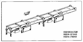
Quantity Variable Speed Belts: Four (belts 1, 2, 3 and 4) per induct line.
Maximum Sorter Speed: 540 fpm.
Rate: 134 cpm at average 24” long product.
Width: A 36” maximum carton width.
Lengths: 28’ total for complete induct assembly.
Safety Pull Cord: Provided along entire length of the induction conveyor for emergency shutdown.
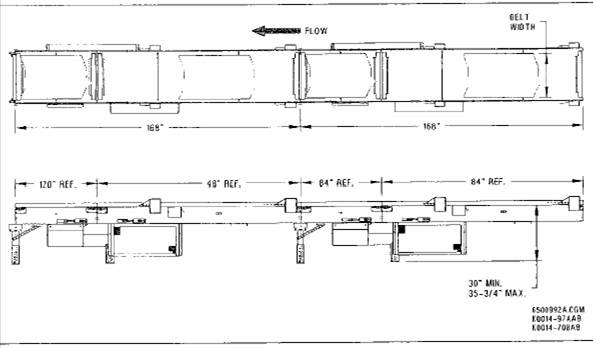
Rev 2005-March-16
79
Model 2421 RS200 Magnetic High Rate Sorter
· 200 Plus Cartons Per Minute
· Interleaving Aluminum Slats
· Durable Divert Shoe
· Quieter Diverts
· Reliable, Quiet Divert Switch Module Designed for Minimum Maintenance and Long Life
The RS200E PLUS™ sorter/conveyor provides reliable tracking and sorting of product regardless of carton size and shape. At divert points, an electromagnetic divert switch automatically activates, and a group of divert shoes slide across the conveyor flights, pushing the appropriate carton onto an outbound conveyor.
Package Weight: 100 lb maximum (50 lb. per ft.), 2 lb minimum. Applications up to 150 lb. are possible in certain applications.
Maximum Sorter Length: 650’ for single units. Multiple units may be installed end-to-end.
Standard Drives: C-face mounted 7-1/2 to 25 hp, 3-phase motor with parallel gear reducer, and cog belt drive.
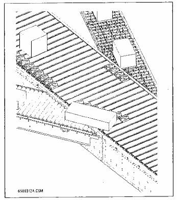
Maximum Rate: Capable of sorting more than 200 cartons per minute (average length 16”).
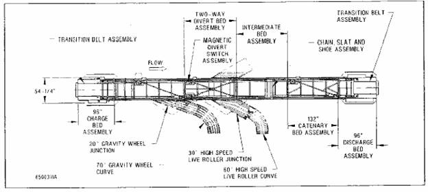
Rev 2005-March-22
80
Divert Switch: An electrically operated magnetic divert switch diverts shoes at each divert point. This divert switch uses an electromagnet to re-direct shoes to divert product when turned on by the magnetic divert switch (MDS) controller. The magnetic divert switch is easily removed through the side frame for inspection without disassembly of the sorter slats.
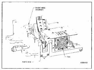
Standard Package Heights: 1” to 30” for photoeye read.
Standard Sorter Widths: Slat surface widths from 46-9/16” to 59-9/16”.
Speed: 275-fpm minimum speed. 540-fpm maximum speed for 20º sorter and 340-fpm maximum for 30º sorter. Speed control set for maintenance, jog and normal modes.
Divert Shoes: Attached to the slats and free to slide along the length of the slats. When shoes pass through a divert switch, they can be re-directed to slide across the slats to divert a carton. While diverting, the shoes are magnetically guided through each divert switch by rolling on a precision ball bearing, to reduce noise. On two-way diverts, a guide vane is located under the ball bearing to steer the shoe through the crossover point. Divert shoes can sort to the right, left or both sides of the conveyor at either a 20º or 30º angle.
Carrying Surface: Flat, anodized aluminum interleaving slats make up the conveying surface of the sorter. Two strands of ASA RC-100 roller chain drive the slats. A slat isolation insert connects the roller chain to the slats to reduce noise. The roller chain is carried on polyurethane wheels with shielded precision bearings.
Controls: Emergency stop pull cord, full-length jam photo eye. Microprocessor control provides lost shoe detection, slack chain detection, and missing pin detection. The MDS controller provides visible LED fault detection, and line fault output is available.
Charge Bed: Supports the tail shaft and chain sprocket. Charge bed includes a transition belt, which transfers cartons onto the sorter from the conveyor feeding it.
Intermediate Bed: Provides transition between other types of beds. 3/16” formed side channels. Bolted, formed channel cross members.
Divert Beds: One or two-way divert beds which include magnetic divert switch/switches with controls mounted near each switch. Controls equipped with quick disconnect fittings. Bed frames the same as intermediate beds. Magnetic divert curves at the end of the divert angles for noise reduction.
Catenary Bed: Includes a one-way or two-way divert and lost shoe sweep angle assembly. A catenary take-up is located in the bottom of the bed to compensate for any slack that may develop in the slat chains.
Discharge Bed: Supports the head shaft and sorter drive. Discharge bed includes a transition belt, which transfers cartons from the sorter to next downstream conveyor.
Options
· Divert left, right or two-way.
· Low Support Assemblies.
· Oil Pans.
· Sound Dampening Panels.
81
6.4 Mechanical Specifications
1. The conveyor equipment to be provided is designed to operate in one (1) direction only unless specified otherwise.
2. All conveyor widths indicated on the Mechanical Equipment list in this Proposal are nominal widths from outside to outside of conveyor beds.
3. Snubber Rollers are equipped with safety guarding unless guarded by location.
4. Protective guarding will be provided on Belt return rollers for slider bed, belt-on-roller, and belt driven live roller conveyors (belt widths greater than 4”) between the elevations of 2 feet - 6 inches and 8 feet - 0 inches above the floor and/or other Personnel walking surfaces as determined by Dematic Application Engineering.
5. Auxiliary take-ups or belt take out sections will be provided on all belt units that Dematic Engineering determines as necessary.
6. Drip pans will be provided under all motors furnished with gear reducers.
7. The system is intended to operate at ambient temperatures of 35 degrees Fahrenheit, to 104 degrees Fahrenheit, 5 percent to 90 percent relative humidity (non-condensing).
8. Manual assistance may be required to initiate and/or maintain the flow of product on gravity conveyor(s). It is understood that due to the inherent characteristics of gravity conveyor, free flow of product may not occur at all times.
9. The provision for header steel and related material or hardware necessary to ceiling hang the conveyors is included in this Proposal.
10. Dematic will supply point loads for ceiling hangers, but it remains The Children’s Place’s responsibility to validate the structural integrity of the structure that the ceiling hangers suspend from.
11. Sound Levels
In most cases, costs are prohibitive when trying to engineer and guarantee noise levels of conveyor systems. Anticipated noise levels can be projected by area, and general noise control practices applied. Once installation is completed, specific things can be done (at an additional cost to The Children’s Place) to reduce the noise of any specific area. This is the most cost effective method of noise control.
Dematic warrants compliance of the proposed conveyor system with the U.S. Department of Labor Occupational Safety and Health Act governing acoustical noise levels within the industrial environment which is in effect at the time of this Proposal.
Dematic does not accept responsibility for compliance of the overall sound pressure levels of the total installation when Dematic equipment is combined with other equipment not supplied or specified by Dematic; nor
82
does Dematic assume responsibility for noise level added to the equipment noise level by the product being conveyed unless specifically agreed to as a result of a thorough analysis and test of the specific products to be conveyed.
12. Paint
a. The majority of this system is comprised mainly of anodized aluminum frames and components, complimented with plastic guarding covers. Conveyor equipment that is to be painted will use powder coating techniques.
b. Powder Coating
With this system, electrically-charged powder is applied to grounded parts. This results in a uniform, resilient finish that resists wear, corrosion, impact, and chemicals. It is a completely dry process, free of runs, drips and sags.
· Gloss: Standard is 65, ±°, or as required
· Hardness: Pencil 2H minimum
· Salt Spray: 96 hours at 100 RH
· Film Thickness: 1.8 to 2.2 Mils
· Metal Preparation: Iron phosphate coating (5 Stage washer)
· Powder Coating Description: Epoxy polyester hybrid
· Color: Light grey RAL 7035
13. Dematic has included the air compressor and air distribution system in this Proposal.
14. Internal air piping of specially fabricated, air operated devices will be terminated at a solenoid valve or filter/regulator unit. All internal air piping will incorporate either barbed or compression type fittings and flexible rubber hose or plastic tubing.
83
7 Controls Equipment Details
The equipment will perform as described when properly managed, operated, and maintained. Please refer to the Dematic drawings referenced on the Title Page of this Proposal while reviewing the rate and equipment listings.
The Control Modules are standard modules and are the same for each conveyor section. All of the control modules are designed to fit into the aluminum side channel. These control modules are electrically activated.
The C-L100 controls software exists in a PROFInet CbA (Component Based Automation) environment and is implemented in conjunction with the C-L100 mechanical and electrical design to ensure a complete mechatronics approach to the product line.
7.1 C-L100 Integrated Conveying Solution
The Dematic C-L100 is a fully integrated automated conveying system. The software, controls, and mechanical devices are integrated into one conveying solution.
This integrated conveying solution offers faster installation, simplified reconfiguration, and control logic modification.
Common standardized controls parts allow for simplified maintenance resulting in easier part replacement and less conveyor downtime.
The Dematic C-L100 conveyor system provides Customers with a fully integrated conveying solution which allows for simplified installation, configuration, and repair.
7.1.1 Dematic C-L100 Product Transportation
7.1.1.1 Product Transportation
Transportation conveyors move cartons, totes, packages or other items from one location to another. The product moves continuously, without stopping and product spacing is maintained.
7.1.1.2 Product Accumulation
· Zero Pressure Accumulation Conveyors are conveyors which allow the product (i.e. -cartons, totes, packages or other items) to queue without
84
applying pressure to the preceding product. If the downstream zone is not full, the product will travel continuously. If the downstream zone is full, the product will stop in the upstream zone.
7.1.2 Controls Architecture
Dematic’s C-L100 controls architecture utilizes a Distributed I/O (DIO) approach.
The conventional controls architecture incorporates devices such as motors, photoeyes, emergency stop switches, etc., which are connected to the control system by way of discrete wiring to control panels located in the general area of the conveyor equipment. One or more of the panels will contain a Programmable Logic Controller (PLC) which controls the system. In most cases, the control panels are custom designed for individual systems.
The DIO approach uses the latest industrial networks to distribute the I/O closer to the control devices and the control devices closer to the equipment. The standard control networks are Ethernet and Profibus.
With DIO, the I/O blocks are located near the control devices. This design reduces the hardware and labor cost of field wiring the devices. The devices are connected to the DIO blocks by way of multi-conductor cables with quick disconnect plugs.
Motorized Rollers are controlled using Brushless Motor Controllers (BMCs) which are located near the motorized rollers, rather than in the control panel. The BMCs are connected to the I/O network by way of multi-conductor cables with quick disconnect plugs. Power is distributed to the starters by way of a power bus feed from a Power Distribution Panel (PDP).
The PDP panels take the place of conventional control panels. PDPs are predesigned and can be stocked or built without additional engineering design time. PDPs contain a PLC, power distribution equipment, emergency stop relays, power supplies and other associated controls devices to control an area of the conveying system.
The PDP panels are connected to PBC by way of the Ethernet network, and can be connected to each other by way of Ethernet.
The Dematic DIO architecture is highly modular and configurable, using standard panel designs.
85
7.2 Control Devices
The Control Modules are standard modules and are the same for each conveyor section. All of the control modules are designed to fit into the aluminum side channel eliminating the need for large custom built control cabinets.
The Dematic C-L100 product line utilizes a distributed controls architecture within the mechatronic design approach. The distributed controls architecture consists of the following devices:
7.2.1 Open Network Cable
The Open Network Cable (LCON) is a PROFIbus network cable that serves two purposes, Communications and Electrical power distribution.
7.2.1.1 Communications
The LCON is a two wire communication network between the various electronic modules mounted in the side channel of the conveyor. Each module on the LCON has a Profibus address allowing for communication with other modules on the LCON. A third wire has been added to the two wire communication network to allow for auto addressing of the control modules.
7.2.1.2 Electrical Power
In addition to the wires used for communication there are three wires used to supply both 24 volt DC and 48 volt DC electrical power. 48 volt DC is used to power and control the powered rollers. The 24 volt DC powers the electronics inside the control modules.
7.2.2 Load Power Supply
The Load Power Supply (LPS) is connected to the AC wiring harness and supplies 48 VDC power by way of the Open Network Cable (LCON) to the powered rollers.
The LPS is mounted under the conveyor inline with one of the cross members. The LPS is supplied 480 volt AC electrical power from an external Power Distribution Panel (PDP). The LPS rectifies the 480 volt AC into 48 volt DC power and supplies this 48 volt DC power to the Brushless Motor Controller through a cable with two D shell connectors on its end. The D shell connectors help ensure that the mating PBC and BMC are properly connected.
86
Figure 3 Load Power Supply (LPS)

7.2.3 Electronic Power Supply
The Electronic Power Supply (EPS) is an electrically isolated power supply connected to the AC wiring harness. The EPS is supplied with 230 VAC and provides 24 VDC power by way of the LCON to the other control components of the C-L100 system.
Figure 4 Electronic Power Supply (EPS)

7.2.4 Programmable Bed Controller
The Programmable Bed Controller (PBC) communicates with the high level devices like the Host Controller and other PBCs by way of Ethernet/PROFInet and the lower control modules by way of the LCON.
Communication between Programmable Bed Controllers is by way of an Industrial Ethernet (PROFInet). PROFInet also allows communications with other systems like scanners, scales, and other field devices.
Figure 5 Programmable Bed Controller (PBC)
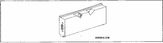
87
7.2.5 Brushless Motor Controller
The Brushless Motor Controller (BMC) operates the 50mm Powered Rollers and provides digital Inputs and Outputs (I/Os) to connect photoeyes, brake rollers, and external equipment to the C-L100 system.
The BMC controls the speed of the powered rollers and also monitors the motor speed, motor current, and motor voltage through Hall Effect Sensors mounted in the motor. This facilitates quick troubleshooting of problematic motors.
Figure 6 Brushless Motor Controller (BMC)

7.2.6 Conveyor Field Switch
The Conveyor Field Switch (CFS) makes it possible to implement additional network subsets and to connect peripheral devices to the system such as scanners, scales, and display marquees.
Figure 7 Conveyor Field Switch (CFS)

7.2.7 Photoeyes and Reflectors
Photoeyes are modular and are integrated within the guide channel. The photoeyes are placed in the guide channel along the top of the conveyor sides. Multiple eyes can be placed in multiple conveyor sections or at the corners of Right Angle Transfers.
Polarized retro-reflective photoeyes and reflectors are available as options.
88
Figure 8 Photoeyes and Reflectors
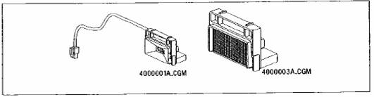
7.2.8 50mm Powered Roller
The 50mm powered roller incorporates a brushless permanent magnet DC motor located inside various roller shells. The shell types used are based on the application. The DC motor allows the speed of the motor to be adjusted to achieve the most effective use of the C-L100 conveyor.
The 50mm powered roller is used to drive all of the conveyor sections with the exception of the Belt on Slider and Belt on Roller Conveyors.
An internal Hall Effect Sensor allows monitoring of the motor voltage, motor current, and motor speed for motor diagnostics.
Figure 9 50mm Powered Roller
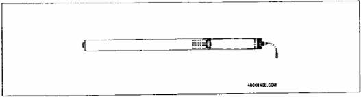
89
Figure 10 Control Devices Overview
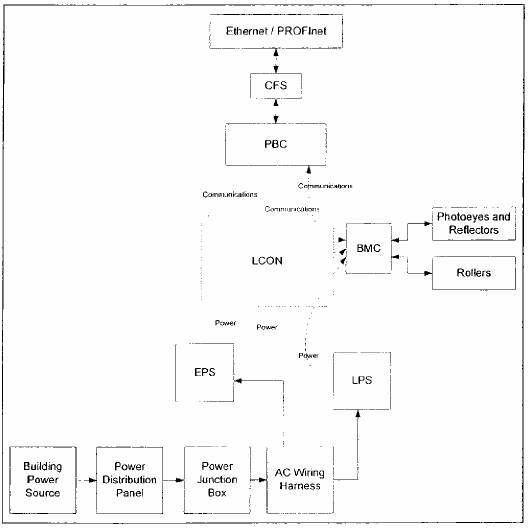
90
The following Figure illustrates the location of these control components.
Figure 11 Side Channel Control Device Locations
7.2.9 Power Distribution Panel
Figure 12 Power Distribution Panel (PDP)

The Power Distribution Panel (PDP) is used to power the C-L100 product line and provides six power branches consisting of high voltage (400-480 VAC, 20 amp) E-stop interrupted power, earth/ground, and low voltage (230 VAC, 3 phase, 5 amp) non-interrupted power intended to provide power to devices such as the EPS that need to maintain power though an E-stop event. The PDP uses hardwiring for all E-stop devices and all PDP interlocking.
The power branch cables are connected at the PDP and then routed to junction boxes located on the conveyor. The power branch is hard wired to the bus located inside the junction box. The junction box is then connected to the AC wiring harness located on the conveyor.
91
There are two E-stop zones (each zone capable of interlocking with up to three other zones) built into the PDP. Power Branches 1, 2, and 3 are controlled by zone 1 E-stops. Power branches 4, 5, and 6 are controlled by zone 2 E-stops. The PDP:
· Provides all electrical power to the C-L100.
· Provides power for both the 24 volt control modules and the 48 volt Powered Rollers.
· Has two E-stop zones. Each zone is capable of interlocking with up to three other zones.
· Has six 20 amp Power Buses, six 3 amp control busses and uses hardwiring for all E-stop devices and all PDP interlocking.
· Houses the power and E-stop capabilities. The AC and E-stop wiring harnesses distribute AC power and E-stop functionality throughout the conveyor system.
· Manages the control signals to components which implement the run-time operation including, but not limited to, Starting, Stopping, and E-stop status.
· Primary functions are the enabling of system control and E-stops within an area of a C-L100 system. The C-L100 uses a distributed controls architecture where control logic is located at the unit. When units are placed together, the units form function groups, and function groups need to be coordinated. Some of the main effects that need to be coordinated are System Enabling and E-stop.
7.2.10 Right Angle Transfer Interface Adapter
The Right Angle Transfer Interface Adapter (RIA) provides an interface between the LCON, BMC, and the servo drive used to operate the RT lift mechanism. Digital inputs and outputs from the BMC are optically isolated before being sent to the servo drive.
Figure 13 Right Angle Transfer Interface Adapter (RIA)

92
7.2.11 T-Outfeeder
The T-Outfeeder (TOF) supplies “outgoing” 24 VDC and 48 VDC as well as Profibus communication to external devices that are to be connected to the C-L 100 system. DC Outputs are filtered, and the Profibus is electrically isolated to prevent interference on the LCON network.
Figure 14 T-Outfeeder (TOF)

7.3 E-stops and Interlocking
The PDP has two E-stop zones. Each zone can be operated independently or both may be interlocked together. All E-stop devices are connected in series for each zone (typically hardwired E-stop devices). Detection by the overall system of individual E-stop actuations is not done by the PDP, but must be done by localized I/O near the device. Any PDP may be interlocked with other PDPs by hardwired connections. Limitations of the interlocking include the following:
· One zone of a PD maybe in interlocked with the other zone of the same PDP.
· One zone of a PDP may be interlocked with up to three other zones of other PDPs.
· “Cascading” E-stops are NOT allowed; each interlock action stands alone.
E-stops are hardwired into the PDP and will interrupt electrical power at the Power Bus eliminating all electrical power to the Load Power Supply and the Powered Rollers.
An E-stop does not drop the 24 volt power from the three Control Buses. Keeping power to the Electronic Power Supplies and the other control modules enables the user to keep track of the packages, jams, and other control functions during an E-stop.
93
7.4 Control Cabinets
The conveyor control system’s architecture is “Local Area Controlled”. This is best described as a localized area having its own control cabinet. Each area cabinet being able to communicates with other areas by way of an Ethernet interface.
These cabinets contain all of the required motor controls and PLC equipment necessary to operate the conveyor system, and will operate from a supply of 480 Volts, 60 Hertz, 3-Phase power, with a voltage variation not exceeding +/- 5 percent of nominal.
All control cabinets are NEMA 12 enclosures and carry a certified UL approval.
A typical control cabinet would contain the following hardware:
· Cabinet disconnect switches
· Fusing / Motor protection
· Motor controls such as starters, timers and control relays
· PLC, Rack, I/O and specialized modules
· Pushbuttons
· Pilot lights
· Terminals, wire ways and other miscellaneous items
All of the area’s motors, sensing devices, E-stop devices, scanners and operator interfaces will be wired back to the local control cabinets.
7.5 Standard Controls Hardware
The control system will use standard electrical hardware components. The following is a brief listing of the electrical hardware and manufacturers typically used on a project of this type. Exact components may vary from this typical listing.
Controls Component |
| Manufacturer |
Control Cabinets |
| Hoffman |
Transformers |
| Acme |
Programmable Controllers |
| Allen-Bradley |
Brushless Motor Controllers (BMCs) |
| Siemens |
Control Relays |
| Square D |
Pushbuttons, Pilot lights, etc |
| Square D |
Limit switches |
| Square D |
94
Controls Component |
| Manufacturer |
Photoeyes |
| Sick |
Horns |
| Federal |
Beacons |
| Square D |
Panel Disconnect Switch |
| Square D |
E-Stop Switches |
| Dematic |
7.5.1 Programmable Bed Controller Features
The system will utilize Windows-based programming software and documentation. The device layout drawings and I/O block schematic drawings will be developed on AutoCAD. The PLC programming software packages will be loaded onto the appropriate PLC programming terminal. The programming terminal will include a PC capable of properly loading and running the PLC programming software packages.
The system will be controlled by a Programmable Bed Controller (PBC). These PBCs will control all of the motor control equipment, sensors, and Operator interface equipment. The system being proposed will utilize Dematic’s System Manager product for diagnostic notification.
Any error or operational conditions that need to be indicated to the Operator will be detected by the PLC system and then shown on the System Manager. The System Manager will monitor the status of the PLCs and report their conditions on the monitors.
7.5.2 Safety Devices
E-stop pushbuttons and pull cord switches will be located throughout the system to assist in providing a safe operating environment. Each PDP and some Operator interface stations will contain an E-stop device. All of these devices will be wired back to their respective PDPs and, by way of hardwired means, will shut off the appropriate areas of control. All E-stop pushbuttons will be of the maintained contact type. This will require the E-stop to be re-set and the system to be restarted prior to any motor control being initiated.
7.6 GSMi Visualization
The web-based GSMi Visualization System provides a centralized organizational point for monitoring a facility’s automated material handling system.
The GSMi Visualization System uses ICONICS™ software to provide a real-time graphical display of the material handling system and status. When problems occur, system alarms generate visual signals. Alarm logs and various diagnostic displays allow further investigation into the cause of a problem.
95
The GSMi receives data from the material handling system and continually displays the data at a computer workstation. GSMi allows for the convenient monitoring of faults and alarms, to retrieve past alarm statistics, or to create and print reports. The GSMi is limited only by the configuration of the controls system and the hardware used within it.
7.6.1 System Overview
The GSMi Visualization System interfaces with the Programmable Logic Controllers (PLC) and the RapidSort Controller (RSC), which control the conveyor hardware. The principle function of GSMi is to monitor and display the state of the material handling system operation.
The GSMi data is accessible from any PC connected to the Distribution Center network by way of Microsoft Internet Explorer. No special equipment is needed to connect to the GSMi site and receive system information.
96
7.6.2 Home Page
After addressing the site in Internet Explorer, the GSMi home page appears. Shown below is a typical home page. This page has links to all the other pages.
Figure 15 Typical Home Page

97
7.6.3 Graphical System Layout
Shown below is a typical Graphical System Layout page. There are three primary areas: menu bar, system view, and active alarm view. This animated display, along with the keyboard and mouse, provides the primary operator interface to GSMi.
Figure 16 Graphical System Layout Screen
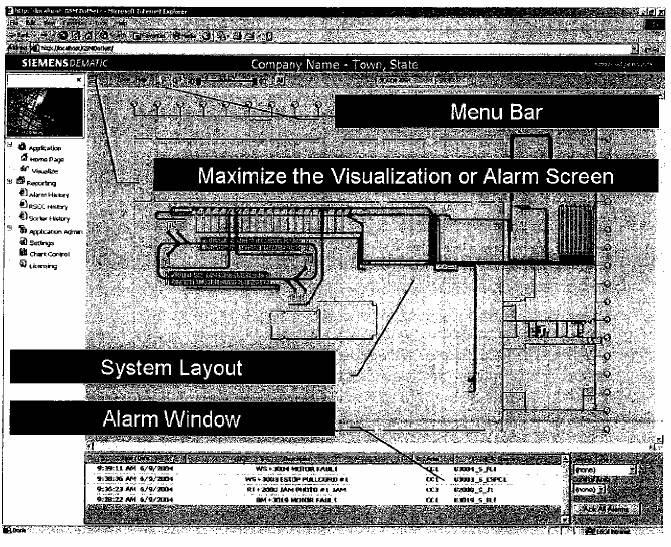
98
7.6.3.1 System View Features
The System View occupies the largest area of the GSMi display screen. At startup, the System View defaults to show the entire material handling system. All conveyors and devices on all levels within the facility are shown simultaneously to provide a single view depicting the entire system status at a glance.
The operational status of conveyors and devices is depicted using color indicators. System fault and event symbols appear within this window, in a position corresponding to the actual event location in the facility.
Navigating this composite image to obtain more detailed information or enlarged views is easily accomplished using mouse or keyboard commands. The following sections give more detail on the components of the graphical system layout.
7.6.3.1.1 Menu Bar
The Menu Bar lists all menu commands and any options selected for each site. This section describes each of the commands available from the Menu Bar.
Figure 17 Menu Bar
![]()
7.6.3.1.2 Zoom Commands
The Zoom commands are used to zoom to a specific area of the system. This will be specific to each project and customer.
Figure 18 Zoom Shortcut Menu
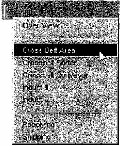
99
7.6.3.1.3 Help
The Help command takes you to an online copy of this manual.
7.6.3.1.4 Toolbar Buttons
The Toolbar buttons are used for navigation within the GSMi system.
· ![]() Box Zoom: This button will zoom to a box. By holding the left mouse button and dragging, you can zoom into a specific area.
Box Zoom: This button will zoom to a box. By holding the left mouse button and dragging, you can zoom into a specific area.
· ![]() Overview Zoom: This button will zoom out to show the entire system.
Overview Zoom: This button will zoom out to show the entire system.
7.6.3.1.5 Elevation Bar
The Elevation bar is used as a filter to show only desired conveyors at a specified elevation. “Stacked” equipment may be viewed by limiting the conveyor elevations that will be displayed. The lower elevation value is set by the green slider and the upper elevation limit is set by the red slider. The “All” button resets the upper and lower limits.
![]()
7.6.3.2 Keyboard Commands
System View navigation may also be accomplished using keyboard and mouse commands.
| To Pan around the layout: Hold the Alt key and Click and Drag using the Left Mouse button. |
| To Zoom: Hold the Alt key and spin the Mouse Wheel. |
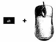
100
7.6.4 Conveyor Colors
Each conveyor section has a single color that indicates its operational state. If more than one state is true at any moment, the software displays the higher priority color as defined in GSMi. Note that some states are specific to particular systems and may not apply.
State Type |
| Color |
| Additional Description |
Non-Powered Equipment |
|
|
|
|
Invalid / Unavailable Data |
|
|
| Communication problem. Power and/or network connections could be the cause. |
Off/ Inactive |
|
|
|
|
Disabled |
|
|
|
|
Running / On /Active |
|
|
|
|
Energy Management (If Used) |
|
|
| Powered off automatically due to lack of product present. |
Full Status |
|
|
|
|
Warning / 100% Full |
|
|
|
|
Alarm / Fault |
|
|
| Alarms should be investigated. |
NOTE If GSMi is not receiving data from the PLC for the conveyor section, GSMi colors the conveyor dark gray, which is the default state.
101
The following Figure is an example of some conveyor colors shown on a system layout.
Figure 19 System Layout Example with Conveyor Colors
102
7.6.5 Symbols
The name of a conveyor section or device may be viewed by positioning the cursor over the item. Zooming in on an area shows additional information such as conveyor unit numbers and conveyor flow direction.
Symbols are specific to each material handling system. Alarm symbols are always red. All symbols will display in the System View, showing the location of the affected device in the facility. Examples of some of the typical symbols are shown below. All of these shown may not be needed.
|
| A red Motor Symbol indicates a motor fault has been activated. These symbols will be displayed in the System View showing the actual location of the motor on the affected conveyor in the facility. |
|
|
|
|
| A red Emergency Stop symbol indicates that an emergency stop button, switch, or pull-cord has been activated. |
|
|
|
|
| A red photo symbol indicates that a jam occurred at the symbol location. The specific type of jam (conveyor jam, chute jam, etc.) will be described in the alarm text displayed in the Alarm Window. A jam is typically associated with a photo eye. |
|
|
|
|
| A yellow or orange photo indicates a flow control condition on accumulation conveyor. This photo will typically be seen on a conveyor unit that is also yellow or orange. |
|
|
|
ALARM TEXT |
| A label in red text may be used instead of a symbol to display selected fault conditions in a custom text window, such as the PLC Status Table. The alarm text will still also appear in the standard alarm window. |

103
7.6.6 Alarms
All alarms are listed in the Alarm Window. The information includes the Time/Date the alarm became active, the Description of the alarm condition, the Area, and the Source of the control network interface Input.
7.6.6.1 Alarm Text Colors
Active alarms are annunciated using red text on a white background. The following chart defines the color scheme for the alarm window.
Type |
| Acknowledged |
| Alarm Source |
| Text Color |
Alarms |
| No |
| Active |
| Red |
|
| Yes |
| Active |
| Blue |
|
| No |
| Inactive |
| Orange |
Figure 20 Alarm Text Example
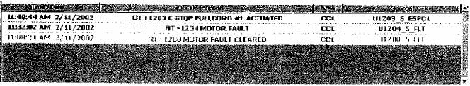
7.6.6.2 Alarm Acknowledgment
Alarms are not removed automatically. They need to be acknowledged to remove them from the alarm window. Alarms are acknowledged by either single left mouse click or by right click then choosing Ack. The following shows the menus for the right-click action.
Figure 21 Alarm Acknowledgement Shortcut Menu
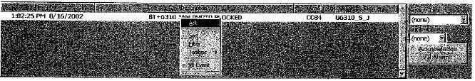
104
The Alarm Ack dialog box allows the user to acknowledge a variety of items depending on the selections made.
Figure 22 Alarm Ack Dialog Box

Clicking the Acknowledge All Alarms button acknowledges all active alarms listed in the Alarm View. This is a one-time acknowledgement action. Refer to the Alarm Filters section, for more details on filtering.
Some alarms (jams, motor faults, E-stops, open gates, open doors, motor disconnect switches, etc.) have corresponding symbols on the screen, others have text representations only. To locate an alarm on the system map, double-click on the alarm text. GSMi positions the screen so the problem area is centered, enlarged, and visible.
7.6.6.3 Alarm History Reporting
When you click on the Alarm History item under the Reporting Root of the Treeview, the Historical Alarm Reporting Screen is loaded in the main window. At first, only the Header and the Report Filters are shown. Do the following to generate a report:
1. Select the filter criteria based on the data you want to report on. (If you do not select filters, you get all data in the Alarm Log)
2. Click on the icon on the menu that corresponds to the report you want (shown below).
3. The Report will be displayed just under the filters.
4. You may choose to change the filters based on what you got back in the report. Change the filters again and make sure that you click on the icon again to refresh the report.
5. To print the report, you may want to modify the appearance of the report. You can hide the filters by clicking on the filter icon on the menu. You can also close the Tree View by clicking on the “x” in the right corner of the Treeview frame. Reports print out the best in the Landscape layout. Printing is done through Internet Explorer.
Additionally, you can save the report to your Favorites. Saving a report to your favorites allows you to recall a particular report you have generated. Saving to a favorite will save the filter criteria for the report only. When a
105
favorite is loaded, the report is run against the active database. Therefore, once data is archived, a favorite might become invalid because the date filter is now not within the active database.
7.6.6.4 Alarm History Report
Below is the Alarm History Report. The information includes the Time/Date the alarm became active, the duration of the Alarm, the Description of the alarm condition, the Area, and the Source of the OPC Input.
Figure 23 Alarm History Report
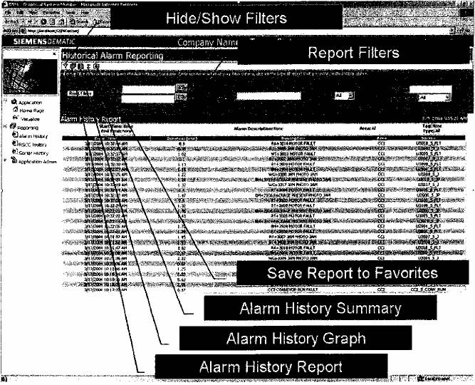
106
7.6.6.5 Alarm History Graph
In addition to the report page the history graph allows you to see a trend over time. Hovering over a point shows the alarm count for that day.
Figure 24 Alarm History Graph
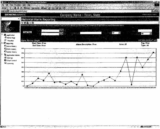
107
7.6.6.6 Alarm History Summary
To see a summary of how often a point has been in alarm, go to the Alarm History Summary. (å) On this screen, the alarm count for each point is displayed along with the point description, area name and source symbol.
Figure 25 Alarm History Summary
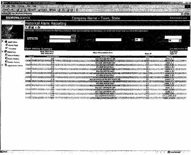
108
7.6.7 RSCC Sorter Errors
All errors associated with the RSCC are listed on the Sorter Error History page.
7.6.7.1 Sorter Error History
All errors are listed on the Error History page. The information includes the time/date the alarm became active, the description of the alarm condition, the area, and the source of the control network interface input.
Figure 26 Sorter Error History
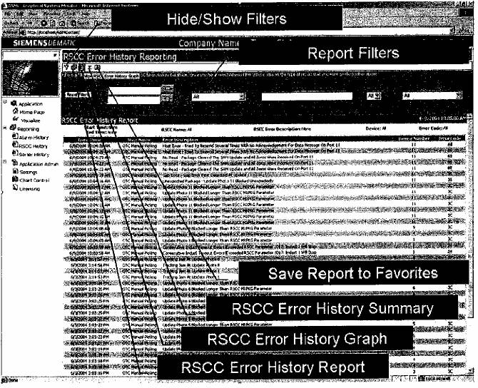
109
7.6.7.2 Sorter Error History Summary
To see a summary of how often a point has been in error, go to the Error History Summary. (å) On this screen, the error count for each point is displayed along with the point description, area name and source symbol.
Figure 27 Sorter Error History Summary
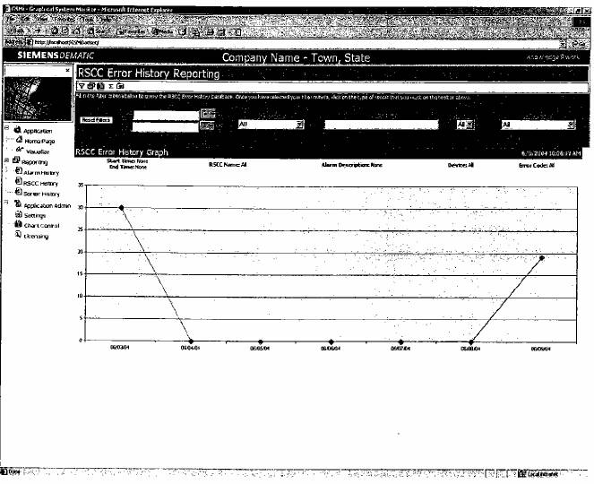
110
7.6.8 Deliverables
7.6.8.1 The Children’s Place
· 120 VAC (isolated) 15A service to all server/workstation locations.
· 120 VAC, 15A to all environmental enclosures (if enclosures provided).
· A drain for condensate from the air conditioning units, on the environmental enclosures, if required by the customer.
· Ethernet network, including drops to all server/workstation locations.
· Dedicated analog phone line to server location unless VPN access is to be granted.
7.6.8.2 Dematic
The base system includes the hardware and software for a single GSMi computer. As an option, extra hardware and software can be purchased to support additional workstations.
· Configuration of software to represent the conveyor system.
· Installation, setup, and checkout of all server/workstations provided by Dematic.
111
8 Computer Information System
This document is to be used as a method of communication between The Children’s Place and Dematic, with regard to the computer architecture and software functionality. An overview of the proposed system is provided here for review, to ensure an accurate understanding by both parties. When this proposal is accepted, a Functional Specification document will be developed, which will contain additional detailed information.
When accepted, the proposed system is expected to be installed around 7/08.
8.1 Integrated Software System – Proposal Overview
Dematic proposes to provide an integrated software system running on an integrated server platform that manages all host communications, picking directives for both put-to-light and all sortation functions. To do this, Dematic integrates its standard Dematic IT Suite software, that is PickDirector®, SortDirector®, and OMS into one harmonized software system – specifically configured for this site’s operations. The modular nature of this software provides the Dematic IT suite of software a common look-and-feel across all system components.
In brief, Dematic proposes the following for The Children’s Place facility in a Ft. Payne, Alabama:
· The installation of a streamlined picking/sortation integrated computer and software solution, including a Windows based computer architecture.
· A single interface between The Children’s Place host and the Dematic supplied software system. This is due to the adroit nature of the Order Management System (OMS), akin to both PickDirector & SortDirector. OMS processes the order picking information downloads from the host and determines the carton destinations within the picking module(s). Message Distributor acts as the traffic director to route picking order data to PickDirector, and carton destinations to SortDirector.
· The installation of a new PickDirector pick-to-light system, including 2640 lights in 240 picking zones.
· The installation of a new SortDirector system, working in conjunction with the conveyor system. SortDirector is responsible for routing cartons and totes on the conveyor system and managing information flow between itself, The Children’s Place Host computer (via OMS), Programmable Logic Controllers (PLCs), Dematic RapidSort Controllers (RSCs), print and apply label printers, carton scales, and all associated scanners.
112
· Client/server based user-friendly operator interface.
· Standard interface to the RSCs.
· Standard interface to the PLCs
· Interface to scanners and printers
· Automatic startup.
· Diagnostics via system logging facilities.
· System error reporting.
· Label lookup and maintenance functions.
· View system operation.
· Single point of control which includes monitoring, access to comprehensive reports and statistics.
· Documentation and on-site training.
8.1.1 Summary of Main Features
· Standard PC-based architecture, with Order Management System (OMS) OMS and SortDirector provide the link between the higher-level Host Computer of Warehouse Management System (WMS) and the lower-level sort controller. OMS provides information on waves, routes, orders, and carriers (cartons/totes/containers).
· Highly flexible/configurable “out of the box” modular software design Modular components can be “shared” between products, giving the Director IT suite of Dematic software a common look-and-feel. Modular component design simplifies customization and troubleshooting activities. Sharing of components means cost efficient development and, known reliability.
8.1.2 Computer Architecture
The following Figure is a sketch of the computer architecture. Please refer to the LAN requirements section for additional pertinent information.
113
Figure 28 Computer Architecture
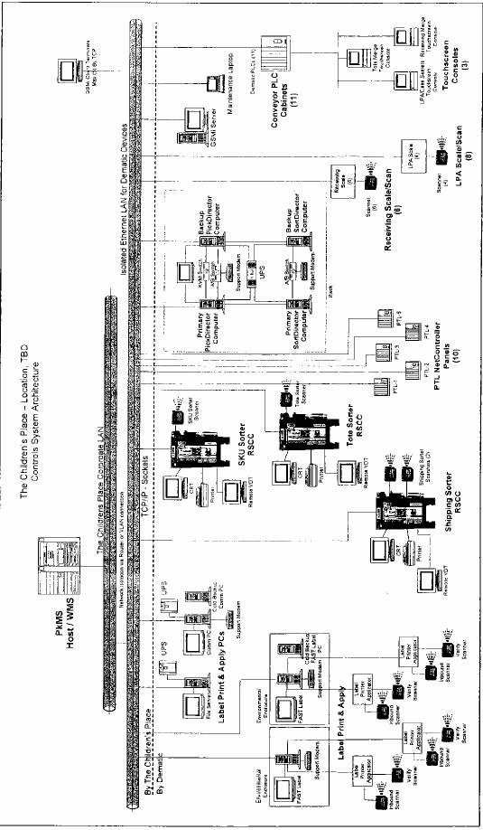
Please refer to Parameters Section regarding LAN requirements, including network isolation, network security, and service packs/antivirus protection and regarding grounding and bonding of computer and communications equipment.
114
OMS serves as the single communication channel between the host computer and the Dematic supplied picking/routing systems. The software interface to the Host System may be via file based FTP or connection-oriented Sockets over TCP/IP.
The details of the host interface functionality are assumed to be identical to The Children’s Place distribution center in Dayton, NJ.
8.2 System Deliverables
Dematic provides the following deliverables:
· Hardware
· Third-party Software
· Dematic Application Software
· Documentation
8.3 SortDirector Overview
8.3.1 Main System Areas
The system can be divided into seven (7) main areas, which are described in further detail in the sections to follow. The list below denotes each area and some of the sub areas contained in each.
1. The Receiving Area
· Five (5) Receiving lines
· Five (5) Barcode Scanners and Weight Scales directly attached to SortDirector
2. Full Case
· Palletizing area used to induct full case cartons into system
3. Put Away/SKU Sorter Area
· Four (4) cross-dock lines to shipping sorter
· 31 Put-Away lines
· One (1) Straight/Recirc line
· One (1) No-Read line
· One (1) Barcode scanner
4. Put-To-Light (PTL)/Tote Sorter
· 20 PTL Pack lines
115
· One (1) Straight/Recirc line
· One (1) No-Read line
· One (1) Barcode scanner
5. The Automatic Label Print and Apply Area
· 4-to-1 saw-tooth merge
· Four (4) Barcode Scanners and 4 Weight Scales directly attached to SortDirector used for Weight Upload to WMS.
6. The Shipping Area
· 40 Shipping lines
· One (1) No-Read line
· Two (2) New-Store loops
· One (1) Straight/Recirc line
· One (1) Barcode scanners
The following areas exist, but are not under SORTDIRECTOR control.
· Inbound Merge Area – sends product towards the Put Away/SKU & Routing sorters
· Outbound Merge Area – sends product towards the print and apply area
· The automatic Label Print and Apply Area
8.3.1.1 Receiving
The receiving system consists of five (5) Receiving lines and one (1) Slapper line each with an associated single-line side-read scanner located on the right-hand-side of the conveyor. Each barcode scanner is attached to a weight scale for a total of six (6) weight scales. The barcode is an input to the weight scale. The scale transmits both the barcode data and weight data to the SortDirector over a direct RS422 serial connection.
Cartons arrive with a unique 20 digit Case Number bar code as well as a four digit Quantity Number. Both of the labels are applied to the right side of the carton and the front of the carton. When a carton is unloaded and placed on one of the two receiving lanes, the associated Receiving Scanner scans the carton for the Case Number and Quantity Number. It is the responsibility of the barcode scanner to concatenate these two strings together for transmission to the SortDirector.
116
The SortDirector formats the scanned data into a DIVERTQUERY message and sends the message to the WMS for notification the case was received. The WMS then downloads the carton information to the SortDirector via the DIVERTDIRECTIVE message.
NOTE If the message from the receiving scanner(s) is a no-read (all zeros) and/or the weight scale is a no-weight, no message will be uploaded to the WMS. No other action is taken by the system for no-reads (i.e. the conveyor does not stop). However, as a result of this, the cartons that encounter a no-read condition on either the quantity or the carton number barcodes and/or a no-weight at Receiving may be sent to the Jackpot lane at Put Away/SKU sorter as an Untranslatable (non in database) if the barcode is successfully read at Put Away/SKU sorter.
The Receiving scanner is not expected to transmit an ID code to the SortDirector, so the SortDirector will need to know which communications port labels are received on in order to report the receiving line the label was scanned.
Table 1 Valid Receiving lane ID’s
Value sent |
| Receiving Lane Number |
R1 |
| Receiving lane 1a and Receiving lane 1b |
R2 |
| Receiving lane 2a and Receiving lane |
R3 |
| Receiving lane 3a and Receiving lane 3b |
R4 |
| Receiving lane 4a and Receiving lane 4b |
R5 |
| Receiving lane 5a and Receiving lane 5b |
R6 |
| Slapper Line |
8.3.1.2 Put Away/SKU Sorter
The Put Away/SKU sorter consists of 31 Put Away/SKU lines and 1 Straight/Recirc line. When the carton arrives at the Put Away/SKU Sorter area it is scanned on the right-hand-side of the carton by the Put Away/SKU Sorter. The bar code is then sent to the RSC which in turn transmits the case barcode to the SortDirector. The SortDirector informs the RSC where to divert the carton based on the data received in the Divert Directive message from the WMS. Upon verifying that the carton has been diverted, the SortDirector sends the Divert Confirm message to the WMS.
When the SortDirector receives the unique tracking number and carton information from the RSC, the SortDirector will take the appropriate action based on the label information received from the WMS. The following table describes the possible actions the SortDirector can take for carton information identified at the Put Away/SKU scanner:
117
Table 2 Put Away/SKU Sorter
Condition |
| Action |
The Sort Lane assignment is a valid Put Away/SKU Sorter Logical Lane number |
| The SORTDIRECTOR informs the RSC to divert the specified carton to the Logical Put Away/SKU sorter lane. |
The “Audit/QC” Flag is set to “TRUE/YES” |
| Overrides the sort destination for the carton and the carton is routed to the Routing Sorter Audit line via the Put-Away/SKU sorter (round-robin diverts 1-3). |
String is anomaly condition (no-read, multi-label, untranslatable/not-in-database) |
| Carton is routed to the Routing Sorter Audit line via the Put Away/SKU (round-robin diverts 1-3). |
NOTE
· Cartons that cannot be diverted due to lane full conditions are re-circulated through the Put Away/SKU sorter line (divert 36).
· When a carton is diverted to the Jackpot/QC lane because of the QC flag being set, the SortDirector also clears the QC flag (space it out) so that it will not be continuously audited.
· Weight checking/validation will take place at PutAway/SKU sorter.
· Cartons destined to the Shipping Sorter merge will use Put Away/SKU Sorter will use the last four diverts however the SortDirector will send a divert value of 1 to the RSC. The RSC will process the divert value of 1 knowing that this is the signal to execute the Round-Robin logic between the last four diverts. The RSC is responsible for the Round-Robin sortation logic when the SortDirector sends a value of 1.
8.3.1.3 Put-To-Light/Tote Sorter
The PTL/Tote sorter consists of 20 PTL lines and 1 Straight/Recirc line. A single RSC controls the PTL/Tote inbound sortation. There is a scanner directly connected to the RSC. The scanner reads the label on the Tote and sends it to the RSC. The RSC, in turn, sends a Dispatch Request to the SortDirector. The SortDirector looks up the label in its database. If the label is found, the SortDirector directs the RSC to divert the tote to the designated destination.
118
Table 3 PTL/Tote Sorter
Condition |
| Action |
String is anomaly condition (no-read, multi-label, untranslatable/not-in-database). |
| Carton is routed to the PTL reject line (divert 41). |
NOTE
· Cartons that cannot be diverted due to lane full conditions are re-circulated through the PTL/Tote sorter line.
· A tote may only have one destination in the PTL/Tote area.
· Divert confirmations are sent to the WMS for this area.
8.3.1.4 Label Print and Apply (LPA)
The Label Print and Apply area consists of 12 Barcode Scanners and 12 Weight Scales. Of the 12 barcode scanners, all are attached to the RSC system and are used for Weight Upload to WMS. All scanners are used by the LPA system. The actual LPA function is not under SortDirector control. Cartons receive a shipping label by a system under control of The Children’s Place.
NOTE The weight that is received from the LPA weight scales must be saved in the SortDirector database as the “Actual Weight” so that weight verification can be processed at the Shipping Sorter.
8.3.1.5 Shipping Area
The shipping area consists of 40 shipping lanes, two New Store loops and a Straight/Recirc line. Configured with the Shipping sorter is one barcode scanner. The scanner in Shipping communicates directly to the RSC and transmits the barcode data to the SortDirector. Both sides of the cartons are scanned for the 20 Digit Case Number Barcode. The left hand side is scanned for the divert directive and the right hand scan is the label verification scan.
The scanners can transmit to the RSC two barcodes separated by an ampersand (“@”), the first being the right side-read (Case Number), ampersand, then followed by the left side-read (Shipping Number).
8.3.1.5.1 Rules for Weight Verification
· If expected weight of Zero is downloaded by host for the carton, weight verification is performed and carton is sent to jackpot.
· If expected weight for the carton is provided by the host, then SortDirector consults the weight tolerance table for the expected weight and computes the upper and lower allowable limits. It then checks, if the measured weight
119
is within these computed limits, if not the carton is diverted to the QC lane (only once for this reason).
· If there isn’t any “actual” weight associated with the carton, the carton should be rejected as a Weight Check Failure. This condition can occur if the weigh station scales/scanners do not transmit the data to SortDirector via the direct device connection. Additionally, for this condition, the carton should continue to be rejected until there is an actual weight available (this is an exception to the QC rule of rejecting cartons only one time).
Table 4 Shipping Sorter Label Verification Logic
Condition |
| Action |
Both strings transmitted by the scanner are the same. |
| The SORTDIRECTOR performs a check of the two strings. The first 20 character string is compared to the second 20 character string. If they match, a lookup is performed in the database for the destination for that carton. |
The two strings transmitted by the scanner are non-zero and do not match. |
| The carton is directed to the Shipping Sorter Jackpot line for a label-mismatch anomaly condition |
If either the first or second string transmitted by the scanner is non-zero and the other string is all zero’s (no-read). |
| A lookup is performed in the database for the destination for that carton. It is then directed to Jackpot. |
NOTE Sortation logic business rules require that the Label Verification logic take precedence over the Weight Verification logic. Weight Verification should only take place once the Label Verification has determined that both labels match.
The SortDirector looks up the label in its database and verifies the actual weight (obtained from the LPA weight scales) against the SortDirector’s configured weight tolerances. If the label is found and is within weight tolerance the SortDirector directs the RSC to divert the carton to the designated destination. If the carton is not within weight tolerance, the carton will be sorted to the designated weight check failure lane. If the carton is a no-read the carton will be sorted to the designated no-read line for the level. If the designated divert is full, the carton will recirculated.
· Label verification will take place at shipping.
· If a carton is rejected for 0 (zero) weight, the shipping label must be taken off before re-inducting the carton to the Routing sorter.
NOTE If the carton is rejected at Shipping sorter for Check-Weight-Failure (out of tolerance), the DIVERTCONFIRM message to WMS must contain the logical destination of WT, otherwise the WMS will mark the carton as “shipped”.
120
8.3.2 Barcode Details
Cartons with this pre-applied case number barcode label are expected to be received at the two (2) Receiving lanes and the Full case lane.
Table 5 Case Barcode Details
Item Description |
| Comments |
Barcode Length and format |
| 20 Digits Numeric |
Information contained in the Barcode |
| Case Number |
Barcode Codification Scheme |
| Type 128 |
Seen by Scanners |
| Receiving Scanners, Primary Sorter, Put Away/SKU Sorter Scanner |
Figure 29 Pre-applied case number barcode label
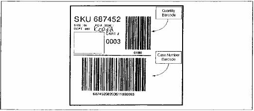
Cartons with this pre-applied quantity barcode label are expected to be received at Receiving lanes.
Table 6 Quantity Barcode Details
Item Description |
| Comments |
Barcode Length and format |
| 4 Digits Numeric |
Information contained in the Barcode |
| Quantity |
Barcode Codification Scheme |
| Type 128 |
Seen by Scanners |
| Receiving Scanners |
The expected format of the transmitted string from the scanner to SortDirector is:
CCCCCCCCCCCCCCCCCCCCQQQQLF
Where:
121
CCCCCCCCCCCCCCCCCCCC is the Case Number and QQQQ is 4-digit Quantity (e.g.: 10 qty will be sent as 0010)
And:
LF is Carriage Return and Line Feed
8.3.3 Client Workstation Details
Dematic configures Terminal Services clients connecting to the server with access strictly to an instance of the DirectorIT™ user interface shell running on the server. When the client logs in, the user is restricted only to the DirectorIT™ application. The user has no access to any system functions and can neither by design or unintentionally reconfigure or reboot the application server from his client session. The client is further restricted by the application login as to what menu options are and are not accessible. Terminal Service sessions can also be configured for timeout by user. The server would automatically terminate client sessions that have set idle for X duration.
NOTE Computer workstations and/or related client hardware/software is not provided by Dematic as part of this project. All client workstations will be configured and run from The Children’s Place computers.
In order for the client workstations to access the Dematic DirectorIT™ server, the client computers require Microsoft Operating Systems of either Windows 2000 configured with Terminal Services or Windows XP Professional configured with Remote Desktop. The client computers must also have network access to the Dematic DirectorIT™ computer.
8.4 PickDirector Overview
8.4.1 Operator Procedure
Inbound totes will be delivered to the appropriate put module by the conveyor system and must be grabbed by the operators of each of the zones for processing.
1. An operator logs into the zone using the hand held scanner and their personal identification barcode.
2. The operator scans one of the inbound tote IDs.
a. If any of the stores that have requirements from that tote, do not have a store carton assigned the MaxiPick will light with the word FILL. The operator will scan a new carton and press the OK button of the corresponding MaxiPick or scan the location barcode. The process is repeated for all the FILL messages. (The POPULATE ALL barcode can also be used to fill any unassigned locations prior to inducting and inbound tote. All unassigned locations will be prompted with FILL
122
messages. The operator scans an outbound carton and presses the OK button on the MaxiPick or scans the location barcode to marry the carton.)
b. PickDirector then lights the appropriate lights/quantities for each store location in the zone that must be filled from this inbound tote.
c. PickDirector also displays the tote ID and total number of stores requiring puts on each BayDisplay in the zone.
d. If the inbound tote has no work in the zone an appropriate message will be displayed to instruct the operator to pass the tote to a zone that has work.
3. The operator picks the product from the tote and places the specified amount in one of the store cartons with a lit MaxiPick. The operator informs PickDirector that the fill is complete by one of the following methods:
a. NORMAL: Pressing the “OK” button to indicate that the put is complete and the store carton is not full.
b. NEW CARTON WITH PARTIAL PUT: Decrementing the quantity and pressing the “Action” button, followed by the “OK” button to indicate that the tote is full, but all puts for the store from the inbound tote could not fit into the outbound carton (another carton is needed). NCAR will be displayed on the MaxiPick for a brief moment to indicate that a new carton is needed.
1) PickDirector turns off all the lights in the zone and waits for the operator to push out the full store carton.
2) The operator will be directed to scan a new carton ID and place it in the store slot.
3) PickDirector lights any remaining quantity for the store that could not be put into the previous carton. Any other stores requiring puts from that tote will also relight.
e. SHORT: Supervisor approval is required to perform a short. In the event there are not enough products to fill the requirement an operator must inform a supervisor. The supervisor decrements the quantity on the MaxiPick to the quantity put and then scans a special ‘Short’ barcode to indicate that there are not enough products to complete the put operation.
4) PickDirector extinguishes all lights in the zone and shorts the requirements for each store.
4. The operator continues step 3 until all store puts are complete for the inbound tote.
a. PickDirector will display the word “COMPLETE” if the inbound tote is supposed to be empty, otherwise PickDirector will display the word “PASS” to the next zone.
123
5. The operator passes the inbound tote to the next zone if instructed to “PASS”. If the tote is empty and “COMPLETE” is displayed the operator will handle the tote appropriately.
6. The operator continues at step 2 until all inbound totes have been processed.
7. The operator can close outbound store cartons by one of the following methods.
a. The operator can swap the carton when it becomes full by using the New Carton process outlined above (NCAR). This method is probably preferred if the operator want to perform a partial put. If the quantity required is 5, but only 3 will fit in the box, using the NCAR method the operator can decrement to quantity to 3, swap the container, and put the remaining 2 in the next carton. OR
b. The operator can swap the carton when it becomes full by scanning the location barcode, pushing out the full carton, and scanning a new carton. No partial put can be done.
c. The operator can scan the “Close All” barcode. This will light all the store locations with CLOS even if they have remaining requirements. The operator can close all locations or can choose specific locations, confirming each action by pressing the “OK” button on the MaxiPick. If the operator only chooses to close specific locations the “End Operation” barcode can be scanned to exit the function.
NOTE At any time during the put process, the put operator may suspend the operation by scanning the “Suspend” barcode. The delivery tote may once again be scanned to resume the put process for those items that have not been completed.
8.4.1.1 Reconfirm Last Put
At any time after a put has been made to a given location, but prior to the next SKU being put at the same location, an operator can relight the last put quantity simply by pressing the OK button. This procedure would be invoked when an operator needs to re-verify a put quantity after it has already been acknowledged at the pick face by pushing the “OK” button.
8.4.1.2 Audit Last Put in Zone
At any time after the last tote has been processed in a zone, but prior to the next tote being inducted in the zone, and operator can audit the last tote. The operator scans the “Audit Last Order” barcode and all locations that had puts from the previous tote will relight with the quantity to be put. Operators can then verify the contents of the outbound containers against the re-lit quantities. No changes can be made to the quantities confirmed to PickDirector. Operators can add or remove items from outbound cartons, but the quantity confirmed to PickDirector will not be updated. Once the operator is satisfied with the audit
124
they scan the “Cancel” barcode to exit the function. To continue operations the operator scans the next inbound tote.
NOTE While auditing, an operator may find more of a SKU in an outbound container than is lit on the MaxiPick. This product would have been put from a different inbound container than the one being audited.
8.4.1.3 Zone Changing via Scanner
During operation an operator may decide to increase or decrease the size of their zone depending on workload. The operator can adjust the size of their zone by scanning a “1 Zone”, “2 Zone”, or “3 Zone” barcode. The zones will automatically resize to a predetermined configuration per aisle. In order to use this functionality, neighboring zones must be logged out.
8.4.2 Email Notification
System Hardware will be configured to automatically email notifications when specific conditions warrant. Conditions include devices not online and shorted orders. It is required that the email system supports Simple Mail Transfer Protocol (SMTP) to accommodate this customization.
8.4.3 Barcodes
The following barcodes are required to commission, test and operate the system after Go Live.
All input barcodes must be alphanumeric, five characters in length and begin with ‘C’. The following are codes for the operations listed:
Operation |
| Code |
Operator Login |
| Any Value |
Operator Log Out |
| C1001 |
Suspend |
| C1003 |
Cancel Operation |
| C1191 |
End Operation |
| C1195 |
Populate All |
| C2022 |
Close All |
| C2030 |
Short |
| C2012 |
Audit Last Tote in Zone |
| C2041 |
Carton at Location |
| C2040 |
125
8.4.4 Quality Assurance
As totes are routed out of the put module, a random number of the totes determined by the host will be routed to an audit divert. If desired a client workstation provided by The Children’s Place can be used to query the contents of any outbound shipping container. The query will display both the required and actual quantity of each SKU in the container as well as the date and time of when the SKU was put and the operator logged into the zone at the time each SKU was put.
Query input to the tote lookup screen can either by the keyboard or by a keyboard wedge scanner. No changes can be made to the query results.
8.4.5 Client Access
For client access System Hardware supports the use of Microsoft Terminal Services. The base System Hardware install allows for 2 simultaneous client connections.
Any windows client can be set up to access the System Hardware user interface by using the terminal services portal. This includes hard network connected workstations as well as RF connected windows based PDA type devices and tablet PCs. For RF connected devices, a tablet PC is better suited for display of the System Hardware GUI Though there is nothing prohibiting the running of the System Hardware GUI on a PDA size display, sliding and scrolling of the screens may be required to access all of the available screen data and controls.
It is the responsibility of The Children’s Place to provide any System Hardware client hardware.
8.4.6 Database Access
System Hardware uses MSSQL for its underlying database. Read only access to the PickDirector database will be granted to The Children’s Place. It is the responsibility of The Children’s Place personnel to familiarize themselves with the System Hardware Database table and index structure in order to create custom SQL database queries. Dematic is not responsible for any performance degradation of the system due to the influence of The Children’s Place generated query against the System Hardware database.
126
8.5 Project Parameters
8.5.1 LAN Requirements
Each computer and each device requires a unique The Children’s Place supplied IP address. The LAN utilizes the TCP/IP protocol running on Category 5E (or above) network cabling according to ANSI/EIA/TIA and NFPA-70 standards. The Children’s Place is to provide all LAN drops and test each drop for all of the normal parameters, including DC loop resistance, continuity, length, attenuation, near-end cross-talk (NEXT), return loss, equal level far-end cross-talk (ELFEXT), propagation delay/delay skew, attenuation to cross-talk ratio (ACR), etc. The interface point is the media interface on the end of the Ethernet cabling with a CAT5E or better connector. This connection point must be within 3’-0” of the usage point.
8.5.1.1 Network Isolation
The Dematic network must be isolated from The Children’s Place business network in order to provide security and manage network traffic effectively.
Dematic recommends that each device be connected to a separate port on an Ethernet switch, so as to isolate collision domains and maximize system performance. Please refer to the Computer Architecture diagram. Isolation is achieved by creating a separate LAN for the Dematic supplied systems. In this example, each of the Dematic supplied servers (primary and backup) is equipped with two NICs. One of the NICs is connected to LAN A (The Children’s Place business network), and the other is connected to LAN B (Isolated LAN for Dematic systems). This arrangement disallows any traffic from LAN A to be broadcast on LAN B, and visa versa. Note that isolation of one network from the other may be accomplished by utilizing a VLAN capable switch or switches.
With this arrangement, all The Children’s Place network traffic is blocked except what is explicitly permitted to/from the Dematic provided servers, i.e. host downloads/uploads.
Implementing systems without isolation such as the method described above compromises the warranty, and does not allow Dematic to control/limit the congestion on its network segment. The added congestion and security risk may interfere with the system design, impeding the operation of the system and Dematic’ ability to effectively support the system as designed.
Ultimately, The Children’s Place is to be responsible for network isolation as outlined above.
127
8.5.1.2 Network Security
The Children’s Place is responsible for managing all network security in terms of prevention, detection, and response.
Network security may include (but is not limited to): physical security, packet screening; vulnerabilities; firewalls; authentication; authorization, and other security issues that may potentially impose risks or threats.
8.5.1.3 Service Packs and Antivirus Protection
Operating systems running on Dematic supplied computers contain the most recent service packs available at the time of software development. Dematic supplied servers and computers also include antivirus software. The antivirus software is up to date and actively running on the computer at the inception of installation. After inception, there are no additional service packs or antivirus patches installed, unless specifically arranged by mutual agreement between The Children’s Place and Dematic.
The warranty provided by Dematic for the installed computer/software system does not apply to any failure that may be caused by vulnerabilities in the operating system, nor does the warranty apply to any attack on the system due to a virus, worm, or other intrusion.
Ultimately, The Children’s Place is responsible for service packs and antivirus protection.
128
8.5.2 Grounding and Bonding of Computer and Communications Equipment
Lightening strikes, electrical power faults, and other transients can cause serious damage to computer and telecommunications equipment if ground loops exist and proper grounding and bonding rules are not applied.
8.5.2.1 Grounding and Bonding Defined
“Grounding” refers to electrically connecting equipment to the earth via the electrical service ground, ground rods, and/or other methods. “Bonding” refers to the equalization of ground points between two or more points – such as between two pieces of equipment, or between a particular piece of equipment and the building’s steel structure.
8.5.2.2 Electrical Grounding vs. Computer Equipment Grounding/Bonding
The purpose of grounding in power systems is to protect people and equipment, while the purpose of grounding and bonding in computer systems is to protect not only people and equipment, but also delicate signals in high speed communications. Each of these systems has specific requirements. Both systems must be installed acceptably and functioning properly, in accordance with national and local electrical codes and also ANSI/TIA/EIA 602 codes and standards. The appropriate ground bus blocks, bonding conductors, connectors, etc. in and between all Dematic supplied racks, enclosures, cabinets, and equipment where communications between subsystems takes place must be installed.
8.5.2.3 Principles Behind Communications Bonding
The majority of distribution center building structures today already have low overall impedance and a lightning protection system to safely conduct direct lightning strikes to ground. However, due to ground loops, significant differences in ground potentials can exist throughout a building during electrical transients. Additional bonding conductors are an effective way to improve marginal situations, especially in buildings that lack an effective overall bonded structure.
A ground loop creates a current across conductors when a difference in potential exists between two grounded points. An example would be two ground points in two separate buildings connected by the same data line. In this scenario, there is a difference in voltage potential between the two points. Current flows through the cable from the higher voltage to the lower voltage. If the voltage potential is large enough, the equipment is not able to handle the excess voltage and one or more parts may be damaged, sometimes severely. Ground loops cannot be tested. Unfortunately, it cannot be known that they exist until a vital component fails.
129
If continuous structural steel already exists nearby along the same path, there may be little actual improvement. But even in this case, a certain assurance is gained by having explicit bonding conductors that can be verified by inspection.
Building Industry Consulting Services International (BICSI®) outlines three of the most important scientific principles behind communications bonding conductors. They are as follows:
1. Equalization: Potentials between different ground points are very dependent on the impedance between them. Ground equalization improves because the additional bonding lowers the impedance between different ground points. The shortest and most direct path using large conductors provides low impedance (both resistive and inductive). Multiple conductors or wide strips provide even lower impedance.
2. Diversion: Because the bonding conductor follow the communications cable and is directly connected to system grounds at each end, electrical transients that are forced down the cable path may be diverted (carried) by the bonding conductor and less likely to influence the communications conductors.
3. Coupling: The closer the bonding conductor is to the communications cable, the greater the mutual electromagnetic coupling. During electrical transients, this coupling tends to partially cancel the transient when it reaches the communications equipment at the end.
Each of these three effects is achieved in varying degrees, depending on a wide range of factors. It is often difficult to predict or measure specific results, but any combination of all three is usually beneficial to computer and communications equipment.
Plainly, the only guard against equipment failure due to lightening strikes and power faults is prevention.
8.5.3 Example - Grounding and Bonding of Dematic Systems
The following Figure is a basic sketch of a properly grounded and bonded sortation system. In this scenario, the sortation system consists of a computer rack (or environmental enclosure) and a Dematic RapidSORT Controller (RSC). This concept may be applied to many other applications wherever computer and/or communications equipment chassis, enclosures, and cabinets are involved.
130
Figure 30 Sketch of Grounding and Bonding of Computer Rack/Enclosure and RSC
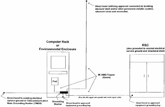
8.5.3.1 Responsibilities
8.5.3.1.1 The Children’s Place’s Responsibilities
· Ensure the integrity of the electrical service ground. This may require the services of a licensed electrician and may involve testing.
· Ensure appropriate grounding and lightening protection for telecommunications circuits (phone lines), network infrastructure, and serial communications systems in accordance with ANSI/TIA/EIA 602 standards.
· Specifically, bond all pertinent cabinets, racks, and equipment to the grounding electrode system (equipment to electrical service ground, equipment to structural steel, and equipment to equipment) utilizing the appropriate bus bars, approved connectors, and #6 AWG copper stranded cable (wire jacket must be green in color).
· Note: Direct attachment to the closest point in the building’s electrical service grounding electrode system is preferred because the communications systems are powered from that service and
131
communications cabling and power cabling must be effectively equalized (Ref.: NEC 80-40).
· Clean all pertinent copper and copper alloy connections (bolt/crimp connectors, clamps, or lugs), and coat with antioxidant prior to connection.
8.5.3.1.2 Dematic Responsibilities
· Provide proper grounding bars and lugs in all Dematic supplied racks, enclosures, and/or cabinets.
· Assess the site for proper grounding and bonding of all equipment during the commissioning period and prior to system acceptance.
8.5.3.2 Grounding and Bonding References
Following is a list of pertinent topics and their associated references. Copies of the National Electrical Code (NEC) code book and information on other standards may be obtained locally at any electrical supply house in most U.S. cities):
· Lightening Protection System (ANSI/NFPA 780)
· Grounding Electrode system (NEC Article 250 Part H, NEC 350-54, & NEC 250-71b)
· Electrical Bonding and Grounding (NEC 250)
· Electrical Power Protection (NEC, Chapter 2)
· Communications Bonding and Grounding (ANSI/NFPA 780, NEC 250, NEC 800-40, and
ANSI/TIA/EIA-607)
· Telecommunications Circuit Protectors (NEC 800C, UL 497)
· Specific Equipment Grounding (NEC 250-45, NEC 250-59)
132
9 Proposal Specifications
9.1 General
1. This Proposal is presented as a total package and, with the exception of any proposed options, must be purchased as such.
2. Dematic in no event shall be liable for incidental or consequential damages (including loss of profits).
3. The Children’s Place will approve and return Dematic’s approval documents within a reasonable time such that the project schedule can be maintained without delay.
4. The concept, design, and drawings for standard and specially fabricated or modified equipment will remain the property of Dematic. Dematic will provide assembly level drawings, including a bill of material, for specially fabricated equipment and Dematic’s standard service/parts manual pages for standard equipment. Detail drawings of weldments, sub-assemblies or individual components are proprietary and will not be provided.
5. Only those items listed in the specific equipment lists in this Proposal will be provided. All other items are presumed to be provided by The Children’s Place.
6. A recommended spare parts list for the equipment under this Proposal will be furnished to The Children’s Place prior to Commissioning. This will allow The Children’s Place to select and purchase spare parts early enough for the spare parts to be on-site for the commissioning process. This spare parts list will include:
a. Item Number
b. Item Description
c. Manufacturer
d. Part Number
e. Price
f. Recommended Inventory Quantity
7. Unless otherwise noted, Dematic has priced this project with the intent to utilize The Children’s Place’s purchased spare parts on an as needed basis during the commissioning phase. Dematic will document all spare parts consumed, and will replenish these parts as quickly as possible.
8. CAD Drawings are included in this Proposal.
133
9. This Proposal does include travel to the site by the Dematic Software Engineers. The software portion of the project is expected to be performed in-house and commissioned by way of modem.
10. Dematic will provide Maintenance and Operation documentation for the equipment installed by Dematic under this Proposal.
11. Full service maintenance of equipment, commencing with the operation of a portion or all of the equipment, is not included in this Proposal but can be quoted separately.
12. Only those work stations, catwalks, platforms, or crossovers specified in this Proposal are included.
13. Fork truck barriers to protect the equipment from damage are not included in this Proposal.
14. This Proposal includes only those interfaces with other equipment specifically noted.
9.2 The Children’s Place Deliverables
The Children’s Place is responsible for the following:
1. Immediate availability of a Project Engineer / Manager authorized to represent The Children’s Place, such that the project schedule may be maintained through the duration of the project.
2. All necessary federal, state, and local government licenses, taxes, permits, and fees as may be required. If required, The Children’s Place is responsible for the costs associated with Dematic obtaining the PE stamp of approval.
3. Ample product for system testing during the installation, commissioning, and testing periods. The Children’s Place will have the equipment and Personnel available, as required, to handle the loading and off-loading of product to the conveyor system. Also, The Children’s Place will have fork trucks and Personnel available, as required, to bring product from its final destination back to its loading point during the installation testing phase.
NOTE A large quantity of product may be necessary, based upon the final system design, system rate, accessibility, etc.
4. Staging of all loads prior to testing which is to include product labeling (machine and/or human-readable).
5. Unique barcode ID’s for all totes and cartons.
6. Training classrooms.
7. Secure storage for backup media.
134
10 Safety
10.1 Mutual Commitment to Safety
Dematic and The Children’s Place recognize that accidents can be reduced by following safe practices in the design, construction, installation, operation, and maintenance of the equipment. Therefore, in a mutual effort to minimize the possibility of accidents, Dematic and The Children’s Place agree as follows:
1. Dematic furnished equipment will be designed, manufactured, and installed under the guidance of the appropriate ANSI/ASME Standards. Likewise, The Children’s Place will apply appropriate ANSI/ASME Standards as they incorporate user instructions into their operations, and will enforce these operating standards and instructions. In particular, The Children’s Place will place into standard operating procedure those instructions contained within the Dematic supplied Conveyor Safety Guidelines Form Number 5100 (9/02).
2. When Dematic provides on-site installation services, Dematic will provide operational and maintenance instructions and training prior to the completion of Commissioning. The Children’s Place will provide the appropriate Operational and Maintenance Personnel for such instructions and training. The Children’s Place will retain a record of attendees.
3. Dematic will provide written instructions relating to the safe use of the equipment. These materials will include such items as manuals, safety instructions, posters, user instructions, etc. The Children’s Place will make such instructions available on a continuous basis to its Operational and Maintenance Personnel.
4. The Children’s Place will periodically conduct safety programs, as required, to keep its Operational and Maintenance Personnel, including new hires, constantly knowledgeable with respect to the safe use of the equipment.
5. The Children’s Place will maintain a dress code which requires all Personnel around the equipment to wear hair protection (or short hair), snug fitting clothes and heavy duty work shoes. The wearing of tennis shoes, baggy cuffs, neckties, jewelry and similar apparel will not be permitted. Hard hats will be worn where Personnel could be subjected to injury because of obstructions or falling objects.
6. The Children’s Place will provide man lifts, platforms or similar devices for the safe maintenance servicing of elevated equipment where catwalks, platforms or similar means of access are not provided.
135
10.2 OSHA Lockout / Tagout Rules
NOTE An important note to The Children’s Place.
On August 28, 1989, the U.S. Department of Labor amended the Occupational Safety and Health Standards to incorporate lockout / tagout requirements. This standard applies to most employers and covers, among other things, “the servicing and maintenance of machines and equipment in which the unexpected energization or start-up of the machines or equipment...could cause injury to employee.” The standard states that servicing and maintenance covers various workplace activities including “lubrication, cleaning or un-jamming of machines or equipment...where the employee may be exposed to the unexpected energization or start-up of the equipment.....”
In Dematic’s opinion, this standard applies to most workplaces utilizing powered conveyor. Dematic is bringing this to the attention of The Children’s Place in the event The Children’s Place is not aware of the standard. Dematic urges The Children’s Place to review the applicability and requirements of the standard with respect to The Children’s Place’s facilities. In general, the standard requires employers to establish an ongoing program of control procedures and employee training (regardless of training provided by the equipment vendor at the time of sale) to ensure that equipment is rendered inoperative before any servicing or maintenance is performed.
The referenced standard (as may be amended) can be found at 29 CFR Part 1910, Section 1910.147; it was published in the Federal Register, Volume 54, No. 169 on September 1, 1989. Also, copies may be requested from the Dematic Contracts Administration Department. This and other pertinent OSHA safety standards may be found at WWW.osha.gov.
136
11 Service Support
Dematic offers a complete range of services to meet The Children’s Place’s needs - from Emergency Service to comprehensive Resident Maintenance Programs. Service options are also available within each service support offering, to tailor the product to best meet The Children’s Place’s specific needs. Material handling system services are one of Dematic’s most important core competencies and have been for decades. This extensive background enables Dematic to provide the highest quality services at competitive prices.
Dematic includes basic service and support as part of every system it sells and installs. These services are designed to make the beginning stages of system start-up and operation simple and efficient for The Children’s Place. The Dematic Service and Support group can help The Children’s Place by answering technical questions, providing training for Operators and Maintenance Staff, and by helping The Children’s Place ensure that the Material Handling system is being properly maintained. The services included with a new Dematic material handling system are:
· Initial Spare Parts Set-up
· Initial Operator and Maintenance Training
· Technical Documentation and E-Manuals
· 1 Year of 24/7 Technical Phone Support
· 1 Year Technical Phone Support Monthly Call Log
· 1 Year Technical Phone Support Annual Call Analysis Report
· 16 Hours of On-site Engineering Support during the 1-year Warranty Period (Can be used for Launch Support, Preventive Maintenance, Assessments, or Training.)
137
11.1 Additional Optional Services Available from Dematic
The programs outlined below can be offered as options to the base system.
11.1.1 Extended Technical Phone Support
Technical Phone Support is available 24 hours a day, 7 days a week and is a critical support service available from Dematic. The Dematic support desk, also known as the Uptime Center, is staffed by qualified Dematic Personnel, not call center operators. These Engineers are knowledgeable experts in the fields of mechanical, electrical, and software applications as they apply to Dematic integrated systems. They have comprehensive knowledge of material handling systems and access to The Children’s Place’s Material Handling system CAD drawings and Operation and Maintenance manuals. This allows Dematic to troubleshoot a wide variety of problems over the phone (over 95% of issues are resolved by phone annually).
NOTE During the original warranty period, Dematic’s Technical Telephone Support (1-800-530-9153) is available 24 hours per day, 7 days per week, at no charge. After the warranty period expires this same high quality support can be continued through a separate support agreement.
11.1.2 Spare and Replacement Parts
To keep Material Handling Systems operating at peak efficiency it is important to replace worn parts with high quality replacements. Dematic uses only top-of-the-line parts. Each part must meet or surpass a series of critical performance standards. With high-quality Dematic replacement parts installed, The Children’s Place should realize longer equipment life, optimized uptime, greater efficiency, maximum productivity, and lower overall life-cycle cost.
Dematic stocks more than 25,000 spare parts in its world-class distribution center, with same-day shipping on most parts. Customers can order parts by phone, fax, EDI or online, 24 hours a day, 7 days a week.
11.1.3 Remote System Monitoring
Remote System Monitoring is a proactive and predictive maintenance program where Dematic Engineers periodically monitor The Children’s Place’s system operating characteristics from a remote location and review error reports using sophisticated visualization software.
If any deviations are detected, Dematic will contact The Children’s Place so that corrective action can be taken. If issues, trends or potential problems are becoming evident, Dematic will proactively alert The Children’s Place so that
138
corrective measures can be taken to avoid serious problems that could affect system uptime and performance.
Dematic will review error logs and faults such as photoeye malfunctions, servo belt errors, scale and scanner issues, and product “no reads”. Dematic will then suggest a course of action to help remedy the problem to avoid future occurrences. Remote System Monitoring also allows us to more accurately analyze system data and measure overall system performance using a variety of KPIs (Key Performance Indicators).
11.1.4 Preventive Maintenance
Correctly performed routine Preventive Maintenance (PM) has been proven to maximize system life, significantly reduce total maintenance costs and dramatically increase system uptime. This program helps provides Return-on-Investment for The Children’s Place’s maintenance dollars by balancing the cost of preventive maintenance against the cost of unscheduled repairs and downtime.
When performing preventive maintenance, Dematic Technicians follow a detailed checklist of tasks specific to each equipment type. Components are inspected, tested, lubricated or adjusted to help ensure quality performance. Any equipment found in need of repair or replacement parts is identified and included in a summary report.
Preventive Maintenance work is scheduled at set intervals throughout the year and at a pre-determined cost. It is completed by Dematic Technicians who are specifically trained to keep The Children’s Place’s system in top mechanical and electrical condition. PM programs are scheduled ahead of time, and since the cost is fixed it is easy to fit into The Children’s Place’s maintenance budget.
11.1.5 Emergency Service
Dematic maintains a staff of Service Personnel who are on-call 24 hours a day, 7 days a week. These professionals are highly skilled at solving mechanical, electrical and software problems, and are strategically located across the country. Dematic Service Personnel are equipped with service vehicles and the tools and equipment necessary to diagnose any The Children’s Place problems quickly and make repairs efficiently. This helps ensure that The Children’s Place’s system is back online with minimal downtime.
11.1.6 On-Site Support
The On-Site Support service program at Dematic provides a team of trained Mechanical and/or Electrical Technicians at The Children’s Place’s site – usually on a short-term basis – to perform specific technical maintenance or training activities. On-Site Support Technicians can help during system launch, a major
139
system overhaul, or to help The Children’s Place establish a site-specific maintenance program. This team of skilled professionals provides technical support, preventive, corrective, and emergency maintenance, and general troubleshooting, as needed, on a daily basis.
Since these individuals are fully trained experts in Dematic systems, they can also provide hands-on training to The Children’s Place operational staff to help ensure peak system performance. The Children’s Place staff is given the opportunity to observe and participate in the regular maintenance of the The Children’s Place system. Dematic Technicians can also assist The Children’s Place staff in periods of special need, such as emergency shutdown and start-up.
Team size and composition can be tailored to meet The Children’s Place’s specific maintenance and budget objectives. This customized program helps create superior support and exceptional system reliability.
11.1.7 Customer Training
Properly trained Maintenance and Operational staff members are a key factor in maintaining optimum system performance. Training programs are available as individually tailored, on-site classroom and equipment instruction taught by the company that designed and engineered The Children’s Place’s individual system.
Dematic’s training approach is different from other companies in that it integrates individual performance into The Children’s Place’s business goals. The training goes beyond demonstrations in starting, stopping, and maintaining equipment. It goes beyond tightening a belt, adjusting a drive chain or replacing a pulley and looks at the full system. Dematic reviews product flow and explains how system performance affects productivity which, in turn, affects The Children’s Place’s internal customers, both upstream and downstream. It places emphasis on how The Children’s Place’s material handling system profoundly impacts its business. Dematic training systems are based on these principles:
· Business goals, such as increased system uptime, reduced costs, and improved productivity, are reviewed to help ensure that each staff person clearly understands his/her role and how their job affects the end-result
· Learning is tightly linked to desired business outcomes
· Each person has numerous opportunities to participate in exercises and hands-on activities
11.1.8 Resident Maintenance Programs
Resident Maintenance Programs provide for The Children’s Place to contract with Dematic for custom, on-site maintenance services for The Children’s Place’s system. This program provides for optimization of The Children’s Place’s system
140
by weighing preventive maintenance costs against the cost of unscheduled repairs and downtime. A team of professional Dematic Technicians will work full-time at The Children’s Place’s site to provide mechanical and electrical system support. This support can be geared for preventive, predictive, corrective, and emergency maintenance, as well as troubleshooting on a regular basis.
The number of employees, number of hours worked, job requirements, and scheduling will be tailored to meet The Children’s Place’s requirements. Resident Technicians can be provided for work in accordance with The Children’s Place’s scheduling. The contract can be designed to provide any level of operations or maintenance that The Children’s Place needs to meet its operational objectives.
Resident Maintenance professionals can be provided to operate equipment, provide routine, corrective, or emergency maintenance as needed, and to troubleshoot The Children’s Place’s system as necessary. They can also be provided to help monitor and maintain material flow throughout the system, and help to ensure that productivity goals are met.
Dematic’s Resident Maintenance Teams provide the best Material Handling contract maintenance services available today. They possess the knowledge, experience, maintenance procedures, tools, and equipment needed to help give The Children’s Place’s operation a competitive advantage. Dematic aligns its maintenance practices with The Children’s Place’s business goals. This means Dematic tracks and measures all maintenance costs including labor, down time, and spare parts usage to help improve throughput and efficiency while helping lower the total cost of operation.
11.1.9 Extended Warranties
Dematic offers a variety of extended warranty programs that extend a new system warranty in yearly increments for parts and/or labor. Extended warranties can be limited to parts replacement only or can be custom tailored to meet the specific needs of The Children’s Place’s operation such as seasonal coverage or hostile environment coverage.
141
12 System Pricing
12.1 Base System
The following prices are provided for the Hardware and Engineering Services as described in Dematic Proposal 103522. The prices and the acceptance of this Agreement by Dematic are contingent upon performing the work under Proposal 103522 in conjunction with the Dematic Proposal Number 104846 dated 2006-September-27 and execution by The Children’s Place of the Agreement for Dematic Proposal Number 104846 dated 2006-September-27.
The price for the performance of Dematic work described in this Proposal is as follows:
Base System Price | Total |
| $11,809,725 |
|
12.2 Pricing Notes
Above pricing does not include building permits, installation permits, or other project permits or fees. All permits and fees are the responsibility of The Children’s Place.
All options are priced to be purchased with the Base System.
Above pricing does not include any sales, use, excise, or similar taxes - these are the responsibility of The Children’s Place. If The Children’s Place is tax exempt, an appropriate tax exemption certificate must be provided within 60 days of order.
Notwithstanding any of the above, within thirty (30) days of signing the Agreement the Purchaser shall have the right to terminate the Agreement upon written notice to Dematic. In the event of such termination, Purchaser shall pay Dematic the reasonable value of the equipment and services already provided to Purchaser.
All prices are in U.S. dollars.
NOTE Commodity Pricing Fluctuations – The metals (steel, aluminum, and copper) to be provided for this project were priced at rates in effect as of the date of this Proposal. Because of the volatility of market prices, any changes in the prices for these commodities from the date of this Proposal to the date on which Dematic ships the equipment, will be charged at “price in effect” on the date of shipment to the installation site. Price adjustments shall be made based upon
142
the changes in the following published price indicators: (1) Steel – Nucor Steel’s price list and surcharges, (2) Aluminum – London Metal Exchange, (3) Copper – London Metal Exchange, which may result in an added charge or credit to The Children’s Place.
12.3 Delivery and Shipping Terms
Delivery and Shipping Terms for the equipment shall be: F.O.B. Destination, Freight Prepay and Add.
12.4 Export Laws and Regulations
The Children’s Place acknowledges that Dematic is required to comply with applicable export laws and regulations relating to the sale, exportation, transfer, assignment, disposal and usage of the work/equipment/services provided under the Contract, including any export license requirements. The Children’s Place agrees that such work/equipment/services shall not at any time directly or indirectly be used, exported, sold, transferred, assigned or otherwise disposed of in a manner which will result in non-compliance with such applicable export laws and regulations. It shall be a condition of the continuing performance by Dematic of its obligations hereunder that compliance with such export laws and regulations be maintained at all times.
The Children’s Place agrees to indemnify and hold Dematic harmless from any and all costs, liabilities, penalties, sanctions and fines related to non-compliance with applicable export laws and regulations that are caused by The Children’s Place’s negligent actions.
12.5 Payment Terms
Dematic agrees to submit invoices and The Children’s Place agrees to pay invoices in accordance with the invoice and payment schedule shown below. All payments shall be made payable net 30 days from invoice date, at the address indicated on the Dematic invoice.
A late payment charge of five one-hundredths of one percent (.05) per day (18 percent annum, based upon a 360-day year) will be added to any amount not received by Dematic on or before the invoice payment date indicated on the payment schedule. Where this rate exceeds a maximum rate permitted by applicable law, the permissible rate will apply.
If this Agreement provides for Dematic to install the Equipment, the final invoice, per the invoice and payment schedule, may be held by The Children’s Place as retainer. The Children’s Place will pay the retainer (final invoice) amount within thirty (30) days after Dematic completion of Installation Commissioning. However, should there be a dispute about the completion of the Installation
143
Commissioning, then The Children’s Place shall inform Dematic of any claimed defects in the Equipment and the amount of any retainer necessary to correct claimed defects will be mutually determined. The Children’s Place will then pay the final invoice less the determined amount. The Children’s Place will pay the remaining retainer upon correction by Dematic of any defects in the Equipment as mutually determined.
Upon contract ratification, the following payment terms apply:
Item |
| Payment Terms |
| Time Frame |
1 |
| Twenty percent of the total project price as a down |
| Upon execution of |
2 |
| Monthly progress payments. (Progress payments |
| Net thirty days. |
3 |
| Five percent retainer |
| Thirty days after system |
12.6 Commercial Terms
This Proposal is based on General Terms and Conditions - Exhibit A. Dematic’s price is based on our standard practices, equipment, Terms and Conditions, and warranty.
144
13 Sales Agreement
This Sales Agreement, (hereinafter referred to as “Agreement”), made by and between The Children’s Place Services Company, LLC, 915 Secaucus Road, Secaucus, New Jersey 07094, (hereinafter referred to as “The Children’s Place”) and Dematic Corp., with headquarters located at 507 Plymouth Avenue, N.E., Grand Rapids, Michigan, 49505, (hereinafter referred to as “Dematic”), constitutes the Agreement of the parties as follows:
1. Dematic agrees to sell to The Children’s Place and The Children’s Place agrees to purchase from Dematic, the equipment and services described in Dematic Proposal Number 103522, dated 2006-September-27, Sections 1 through 13, for the price set forth in the Proposal and on the General Terms and Conditions – Exhibit A.
2. This Agreement constitutes the entire agreement between the parties and no oral or other representation shall prevail, notwithstanding any other terms and conditions of any order submitted by The Children’s Place. Any changes, modifications, or additions to this Agreement are binding and enforceable only if made in writing and signed by both parties.
Approved and Executed By:
The Children’s Place Services |
| Dematic Corp. |
|
|
|
/s/ Sal Pepitone |
|
|
Signature |
| Signature |
|
|
|
Sal Pepitone |
|
|
Name (please print) |
| Name (please print) |
|
|
|
VP of Logistics |
|
|
Title |
| Title |
|
|
|
9-29-06 |
|
|
Date |
| Date |
145
13.1 General Terms and Conditions – Exhibit A
The Dematic Corp. (“Dematic”) Proposal and Sales Agreement specifically incorporate the following General Terms and Conditions. Collectively the Proposal, Sales Agreement, and these General Terms and Conditions are referred to herein as the “Agreement” between Dematic and The Children’s Place.
146
GENERAL TERMS AND CONDITIONS |
| Exhibit A |
|
|
|
The following General Terms and Conditions shall apply to any resulting order between Dematic Corp. (hereinafter referred to as “Dematic”) and Purchaser.
1. TAXES: Unless otherwise indicated, the price does not include any sales, use, excise, or similar taxes, and Purchaser shall be responsible for all such taxes, whether or not invoiced by Dematic. If taxes are included as part of the price and the rate or base of the tax is increased or decreased, Purchaser will pay any increased taxes, and Dematic will give credit for any tax decrease. Absent written agreement to the contrary, Dematic will pay the tax and be reimbursed by the Purchaser.
In the event Purchaser is exempt from such taxes or should Purchaser elect to pay such taxes directly to the taxing authority, then within 60 days of the order, Purchaser will provide Dematic with a valid tax exemption certificate or similar document satisfactory in form to Dematic.
2. WARRANTY: Dematic warrants that goods sold by Dematic will be free from defects in material and workmanship for a period of two years from the date of installation or four thousand hours of operation, whichever occurs first. Dematic’s obligation under this warranty is limited to repairing or replacing, at Dematic’s option, F.O.B. manufacturing plant, any part of the goods found to be defective within the warranty period. This obligation is conditioned upon receipt by Dematic of prompt written notice of the claimed defect, including a description of the defect and its discovery, and the opportunity for Dematic to inspect the goods in the purchaser’s facility. This obligation does not include costs of labor or other charges incurred in removing or reinstalling parts, and does not apply to goods damaged by misuse, neglect or accident or to goods which have been improperly applied, installed, adjusted, operated, maintained, repaired or altered by persons other than Dematic.
If the goods include computer hardware or software acquired from original manufacturers, Dematic’s obligation will be limited to conveying and transferring to Purchaser any interest, rights and/or warranties which Dematic may obtain.
DEMATIC MAKES NO ADDITIONAL WARRANTIES, EXPRESS OR IMPLIED, AS TO ANY GOODS, AND IN PARTICULAR DEMATIC MAKES NO WARRANTIES OF MERCHANTABILITY OR FITNESS FOR ANY PARTICULAR PURPOSE.
3. INSURANCE BY DEMATIC: Dematic will maintain insurance covering its operations as follows:
a. Worker’s Compensation Insurance as required by the state having jurisdiction over Dematic and Employer’s Liability with limit of $1,000,000.
b. Commercial General Liability Insurance with combined single limit for bodily injuries and property damage of $1,000,000.
c. Automotive Liability Insurance for bodily injuries, including death and property damage with combined single limit of $1,000,000.
Dematic may, at its sole option, satisfy these requirements with commercial insurance or through a program of combined self-insurance, self-insured retention, and excess insurance.
Certificates of insurance or letter of authority to self-insure will be furnished upon request.
4. INSURANCE BY PURCHASER: Purchaser assumes all risk of loss from damage and destruction of the material and equipment and any applicable installation charges thereof. Such risk of loss will transfer to Purchaser at the F.O.B. point pursuant to the shipping terms of the Agreement (F.O.B. destination). Purchaser agrees to acquire and maintain all risk insurance covering damage and destruction of the materials and equipment at replacement value and in no event less than the purchase price including any increases by change order(s). The insurance policy or policies shall include Dematic as an insured, shall provide for 20 days prior notification to Dematic if the insurance coverage is terminated, reduced, or otherwise materially modified, and shall provide that the insurance proceeds shall be payable to Dematic and Purchaser as their interests may appear. Payments made by an insurance carrier to Dematic as a result of such damage or destruction of the equipment will be applied against the purchase price and any other amounts owed by Purchaser under the Agreement. Purchaser shall furnish Dematic with certificates evidencing such insurance.
5. INDEMNIFICATION: The equipment furnished hereunder will be manufactured with Dematic safety features and furnished with user safety instructions. The operation of the equipment with safety features removed or modified and/or the disregard of the user safety instructions is outside of Dematic’s control and is the responsibility of the Purchaser. Therefore, Purchaser agrees to indemnify and hold Dematic harmless from any and all claims, demands, liabilities, causes of action, suits, costs, and expenses of any kind or nature (including attorney’s fees) for loss or damage which may be suffered by Dematic as a result of injury to persons arising from such removal or modification to Dematic-furnished safety features and/or the disregard of Dematic-furnished user safety instructions, including any person injured while riding, sitting, stepping, walking, or climbing on the equipment furnished hereunder; Provided that Dematic notifies Purchaser in writing, within 30 days of Dematic’s knowledge of any such claim, and gives Purchaser the exclusive control of the defense and settlement of any claim.
Dematic agrees to indemnify and hold Purchaser harmless from any and all claims, demands, liabilities, causes of action, suits, costs, and expenses of any kind or nature including attorney’s fees) for loss or damage which may be suffered by Purchaser as a result of injury to persons arising from defects in material and workmanship of the equipment caused by Dematic. Provided that Purchaser notifies Dematic in writing, within 30 days of Purchaser’s knowledge of any such claim, and gives Dematic the exclusive control of the defense and settlement of any claim.
6. CHANGE ORDER: The parties may agree at any time prior to final payment of the Agreement to make additions, deletions, or other revisions by Change Order or Work Order (as defined below) without invalidating the Agreement. No such change will be performed by Dematic until an approved Change Order or Work Order is executed as provided below.
a. When the price, schedule and other conditions relating to the change can be determined prior to the start of work under the change, a document describing this change (Change Order) will be issued for execution by the parties.
b. When the change requires immediate action and the issuance of an executed Change Order with firm price would unreasonably delay the change, Purchaser shall place its signature upon a document authorizing Dematic to proceed with the change (Work Order). After the change under the Work Order has been completed, Dematic will calculate the firm price for the change using actual costs (including overhead and reasonable profit) current at time of performance of the
147
work. Completed Work Order(s) will be incorporated into a Change Order for execution by the parties.
Unless expressly modified by a Change Order or Work Order, the provisions of the Agreement will govern all work performed under such Change Order or Work Order.
7. LIENS: Dematic will protect Purchaser as to any lien asserted against Purchaser’s property for work, material or services furnished by others at Dematic’s request when Purchaser makes the payments provided for in the Agreement.
8. RIGHTS AND REMEDIES: If Dematic defaults in the performance of any of its obligations under the Agreement (other than its obligations under Article 2 hereof) and if Dematic has not cured the default or implemented a plan to cure the default in a diligent manner within 20 days after Purchaser shall have given Dematic written notice of the default, or such other time period as mutually agreed upon, Purchaser shall have the right to terminate the Agreement upon written notice to Dematic. In the event of such termination, Purchaser may (i) pay to Dematic the reasonable value of equipment and services already provided to Purchaser, or (ii) complete the work specified in the Agreement.
If Purchaser elects to complete the work and the reasonable costs of completion exceed the unpaid balance of the Agreement price, Dematic shall pay the difference to Purchaser. If the unpaid balance of the purchase price exceeds the reasonable cost of completion, Purchaser shall pay the difference to Dematic.
If Purchaser fails to pay the purchase price, or any installment thereof, within 10 days after it is due, or if Purchaser defaults in the performance of any of its other obligations under the Agreement and if the default continues for 20 days after Dematic gives Purchaser written notice thereof, or such other time period as mutually agreed upon, then Dematic shall have the right to (i) suspend performance of its obligation under the Agreement until the default is cured, or (ii) exercise any right or remedy provided for in the Agreement, or available to Dematic under applicable law.
9. SECURITY INTEREST AND TITLE:
a. Subject to any interest that Wells Fargo Retail Finance, LLC has in the equipment pursuant to the credit facility dated November 21, 2004, as amended between the purchaser and Wells Fargo, Dematic retains a security interest in the equipment to secure the purchase price payable by Purchaser under the Agreement and all other amounts now and hereafter owing by Purchaser to Dematic hereunder. Upon request by Dematic, Purchaser will execute and deliver to Dematic a financing statement evidencing this security interest.
b. Dematic hereby grants Purchaser a single site non-transferable and non-exclusive license to use all computer software manufactured and provided by Dematic under the Agreement. Title to the software and documentation, if any, provided hereunder shall at all times remain with Dematic. Purchaser agrees to use such software strictly in compliance with the terms of the Agreement, and for the use(s) contemplated herein, and specifically agrees not to copy, furnish, disclose, or otherwise make said software, or any portion thereof, available to any third party.
c. The Dematic manufactured and provided software is a proprietary trade secret of Dematic. Purchaser agrees to maintain confidentiality of Dematic software, and to restrict access to Purchaser’s employees or agents directly concerned with Purchaser’s licensed use of same.
d. Refer to Article 2 for provisions of title for software which Dematic acquires from original manufacturers.
10. DELAYS: If Dematic’s performance is delayed or prevented by Purchaser or other cause uncontrolled by Dematic (such as casualty, labor trouble, governmental action, inability to obtain supplies or transportation, or any order modification by Purchaser):
a. Purchaser agrees to pay Dematic invoices upon notification that equipment is ready for shipment in accordance with the shipping schedule and to reimburse Dematic for expenses incident to such delay including, without limitation, the cost of engineering, equipment and installation escalations; maintaining, repairing and refurbishing equipment, storage, demurrage, and pullout charges from installation site; and
b. The time for delivery of the equipment and performance of the services will be extended accordingly, and Dematic will not be liable for any damages caused by the delay; and
c. The stated purchase price shall be revised based upon labor wage rates and other conditions prevailing at the time of actual performance.
11. PATENTS: Dematic agrees to indemnify and hold Purchaser harmless from any damages (including litigation costs incurred) that may be awarded against Purchaser in any final judgment based upon a claim that the equipment or its use infringes any currently existing United States patents owned by third parties, provided that Purchaser notifies Dematic in writing, within 30 days of Purchaser’s knowledge of any such claim, and gives Dematic the exclusive control of the defense and settlement of any claim, including the right to make changes in the equipment to avoid any alleged infringement, so long as such changes do not materially affect the performance of such equipment which shall be determined by the Purchaser in its sole reasonable discretion. Purchaser is responsible for any infringement claim arising from any modifications of the equipment by Purchaser or any combining by Purchaser of the equipment with other equipment not furnished by Dematic.
12. ASSIGNMENT/SUBCONTRACTS: Purchaser shall not delegate the performance of any obligation hereunder, nor assign any rights arising under the Agreement, to any unaffiliated third person without the prior written consent of Dematic.
Dematic reserves the right to use subcontractors in the performance of any services to be performed by Dematic. Dematic is responsible for the acts and omissions of any subcontractor so engaged.
13. LIMITATION OF REMEDIES/GOVERNING LAW: The Agreement sets forth Purchaser’s sole and exclusive remedies for any defect in or non-conformity of any equipment or services and for any negligent design, manufacture, or installation of the equipment, and for any breach of the Agreement by Dematic. Neither Dematic nor Purchaser shall be liable for incidental or consequential damages (including loss of profits).
The Agreement shall be interpreted and enforced in accordance with the substantive laws of the State of Michigan.
148