Exhibit 10.2
| The Children’s Place
Project 104846 |
Creating Logistics Results | | DEMATIC |
| Proposal for Conveyor System |
Introduction
Dematic’s goal is to provide The Children’s Place with the best system solution available, including cost-effective technologies, control systems, software, visualization systems, integration and services. This will help The Children’s Place to optimize service to its customers, reduce distribution lead-time, enhance material tracking, and support reduction of overall operating costs. We look forward to working together with The Children’s Place to build this innovative Material Handling System.
Executive Summary
This Proposal covers a Material Handling System encompassing Third-party commodities, Mechanical Installation, and Electrical Installation and is summarized with the following tasks.
Mechanical Installation
Dematic Mechanical Installation will install the Material Handling Equipment and related accessories as specified within the Proposal. Dematic’s Installation Lead will serve as the Site Manager, attending meetings, interfacing with The Children’s Place representatives, and coordinating on-site activities.
The installation includes:
· Receiving and unloading of equipment
· Assembly and placement of equipment
· Hardware commissioning and run-in
· On-site representation by Project Engineer and/or Project Installation Foreman
Electrical Installation
Dematic provides the Field Wiring of the Material Handling Equipment and related accessories, as specified within this Proposal, which includes:
· Setting the control cabinets
· Control wiring from supplied cabinets to the equipment
· Remote control devices and mounting of the control devices
The Children’s Place will provide wiring from the building power source to the control cabinet(s).
i
ISO 9001:2000 Registered
Dematic is registered to the ISO-9001:2000 International Standard for Quality Management Systems.
The registration applies to all Dematic Manufacturing, Engineering, Project Management and Customer Service processes.
Revisions
Revision Level |
| Date of Revision |
| Date of Revision |
|
| 2006-September-27 |
| Initial Release. |
| |
|
|
|
|
|
|
|
|
|
|
|
|
ii
Table of Contents
| 1 | ||
| 2 | ||
|
|
|
|
| 3 | ||
| 3 | ||
| 4 | ||
|
|
|
|
| 5 | ||
| 6 | ||
| 7 | ||
| 9 | ||
| 10 | ||
| 11 | ||
| 12 | ||
| 35 | ||
| 37 | ||
| 39 | ||
| 44 | ||
|
|
|
|
| 45 | ||
| 45 | ||
| 47 | ||
|
|
|
|
| 49 | ||
| 49 | ||
| 50 | ||
|
|
|
|
| 51 | ||
| 51 | ||
| 53 | ||
|
|
|
|
| 57 | ||
| 57 | ||
| 57 | ||
| 59 | ||
|
|
|
|
| 61 | ||
| 61 | ||
| 62 | ||
|
|
|
|
| 63 | ||
| 63 |
iii
| 63 | ||
| 64 | ||
| 64 | ||
| 65 | ||
|
|
|
|
| 66 | ||
| 67 |
iv
Dematic Corp. (hereinafter referred to as “Dematic”) with offices located at:
6 Powder Horn Drive
Warren, New Jersey 07059
Submits this Proposal to: | Equipment to be installed at: |
|
|
The Children’s Place Services Company, LLC | The Children’s Place |
|
|
915 Secaucus Road | Airport Road West |
|
|
Secaucus, New Jersey 07094 | Fort Payne, Alabama 35968 |
|
|
Don Whiteford | Don Whiteford |
This Proposal consists of the following:
1. Sales Agreement No. 104846, including General Terms and Conditions - Exhibit A.
2. Sections 1 through 10.
3. Dematic drawings: Q103522-C010, Rev. C, Sheets 1 and 2, Dated September 6, 2006.
4. Other documents: None.
If information in any document conflicts with that in another, governing priority shall be given to documents in the order listed above.
All information in this Proposal is confidential and has been prepared for The Children’s Place’s use solely in considering the purchase of the equipment and/or services described herein. The Children’s Place’s use for any other purpose, or transmission to others of all or any part of this information, including, but not limited to, drawings, process flow diagrams, sequence of operation, and pricing, is unauthorized without Dematic’s prior written consent. All Dematic specifications and drawings remain the property of Dematic and are subject to recall at any time.
© copyright 2006, Dematic Corp. All rights reserved. The contents of this Proposal may not be reproduced without the prior written permission of Dematic Corp.
This Proposal is submitted by:
/s/ Thomas R Dancer |
| Business Development Manager |
| 732 563-1330 ext. 300 |
Thomas Dancer |
| Title |
| Phone |
|
|
|
|
|
/s/ John Van Walleghem |
| General Manager |
| 732-563-1330 ext. 500 |
John Van Walleghem |
| Title |
| Phone |
The Offer Period for this Proposal shall terminate 30 days from the date of this Proposal. Dematic may extend the Offer Period; however, the price, schedule, and other portions of this Proposal may be subject to change. Extensions of the Offer Period shall be valid only if in writing and signed by an authorized Dematic representative. This Proposal shall become binding only upon full execution of the Sales Agreement by duly authorized agents of the parties.
1
This Proposal is provided to furnish all of the necessary Third-party commodities, Mechanical Installation, and Electrical Installation for The Children’s Place material handling system. This Proposal must be purchased with Dematic Proposal Number 103522, which provides all of the necessary Hardware and Engineering Services.
This Proposal is summarized as follows:
· Supply of Third-party Mechanical Resale
· Supply of Third-party Controls Resale
· Supply of Third-party Computer Resale
· Mechanical Installation - Installation of all conveyors and conveyor accessories specified in Dematic Proposal Number 103522. Receiving, unloading, rigging and placement of conveyors will be performed by Dematic.
· Electrical Installation - Field wiring of all conveyors and conveyor accessories specified in Dematic Proposal Number 103522. This includes setting the control cabinets, connecting the power and control wiring from these cabinets to the conveyors and remote control devices and mounting the control devices. Wiring from the power source to the control cabinet(s) to be provided by The Children’s Place.
2
The following scope of work is intended to be comprehensive, based on Dematic’s knowledge and understanding of the project. The Engineering and Design effort is expected to be a confirmation of the scope listed below. In general, The Children’s Place is responsible for any scope not specifically identified as Dematic’s responsibility.
Dematic Deliverables |
| Comments |
Mechanical Resale |
| Consists of the following equipment: |
| · Air System including: | |
| · Air compressors | |
| · Air piping | |
| · Air drops with shut-off valves | |
| · Air hookup kits to equipment | |
| · (2) Balers | |
| · (2) Carton Erectors | |
| · (4) Semi-Automatic Carton Sealers | |
| · (4) Dunnage Fill | |
| · (18) Weigh Scales | |
| · (5) Trailer Unloaders | |
| · (42) Trailer Loaders | |
| · Overhead Chain Conveyor | |
| · Platforms | |
| See the “Mechanical Resale Equipment Details” Section for specific details. | |
|
|
|
Control Resale |
| Consists of the following equipment: |
| · Motor Control Cabinets | |
| · Label Print and Apply System | |
| · (12) Shipping LPA Lines | |
| · (2) Carton LPA Lines | |
| · Scanners necessary to route product. | |
| · RapidSORT Controllers for carton routing on sorters. | |
| · GSMi Visualization System application hardware. | |
| See the “Controls Resale Equipment Details” Section for specific details |
3
Dematic Deliverables |
| Comments |
Computer Resale |
| Interface to The Children’s Place’s WMS |
| · SortDirector and PickDirector applications Hardware. | |
| See the “Computer Information Systems” Section for specific details. |
Dematic Deliverables |
| Comments |
Mechanical and Electrical Installation |
| Installation of all Dematic provided equipment. Installation will be non-union / non-prevailing wage labor. Installation includes unloading of all Dematic-supplied equipment. Changes to the project schedule or labor may effect the installation time and costs. |
|
|
|
Installation Supervisor |
| Will coordinate on-site activities and supervise installation of all Dematic-provided equipment. |
4
3 Mechanical Resale Equipment Details
The Detail Sheets for the equipment in your system follow.
5
Two (2) Balemaster EO-6430 Balers to Include the Following:
· All necessary feed chute to accommodate a 24’ discharge height
· (2) Balemaster EO-6430 Auto-Tie Horizontal Balers
· Air/Oil Cooler (Heat Exchanger) and Select-O-Matic Controls
· Dust tight, gasketed 22” x 22” windowed feed chute door
· Fused Electrical Disconnect Switch integrated with high voltage motor starter cabinet
· Touch Screen Control complete with screen saver
· Extra Heavy Duty Automatic Wire Tier and Inserter
· Bale Run-Out. Solid Slide Bed Conveyor per 5’ section. (1) section per baler
· Regenerative Hydraulic Circuit for up to 25% faster Baling Ram Speed
· Totally Enclosed Fan Cooled (TEFC) High Efficiency Motor
· Dual Motor/Dual Pump arrangement with Automatic Selector Controls
· SONAC High Level Eye for each feed chute
· Mechanical Installation Package
3.1.1 Mechanical installation package to include the following
· Mechanical installation labor
· Lifting and rigging equipment
· Field crew travel and living expenses
· Detailed approval and equipment layout drawings
· Single-line electrical diagrams
· Dedicated project management
· Consultation with electrical contractor and related trades
· System start-up and operator training for two days on-site
· System operation, maintenance and owner’s manual
6
| Future Commodities Int’l Inc. |
|
| CLASSIC PRINTERS |
World Leader in Sophisticated Packaging Systems | 140 Ethel Road West Unit K • Piscataway, NJ 08854 | |||
· Carton Size: L: 18.5” W: 16.25” H: 15.5”(RSC Type Carton)
· Most important carton 18.5 x 16.25 x 15.5”
· Electrical: 110V, 60Hz, Single Phase, Omron PLC
· Air Requirements: 100 PSI, 10 + CFM, (Dry AIR) Lubrication Free
3.2.1 Standard Features:
· Carton is straight fed from the hopper / bottom pulled
· Output: 10 cartons per minute
· Hopper capacity of 70-100 cartons
· PLC logic
· Suction cup system
· Quick positive size change over
· Heavy-duty construction
· Malfunction alarm with two-colored light
· Carton is sealed form the side
· No tape on the carton alarm
· Heavy-duty castors or peg legs
3.2.1.1 The Children’s Place needs the following before the equipment is installed:
· Dedicated 110V line 20 AMPS
· Minimum 100 PSI with 10 + CFM
· Air must be dry
· Airline to the sealer must be a minimum of ¾” I.D., 1” I.D. or larger is needed if the compressor is considerable distance from the sealer or if running multiple lines.
7
NOTE
· An application survey and carton samples must be submitted to confirm details; final details may affect final pricing.
· Cartons must be tested before shipment of equipment. Please send cartons for testing flat, and 50 cartons of each size.
· This carton erector will set up carton with flaps being folded down.
· Installation must be preformed by approved BestPack Representative for full warranty to be in effect.
8
3.3 Semi-Automatic Carton Sealer (MQ22)
| Future Commodities Int’l Inc. |
|
| CLASSIC PRINTERS |
World Leader in Sophisticated Packaging Systems | 140 Ethel Road West Unit K • Piscataway, NJ 08854 | |||
3.3.1 Standard features
· Box size W: 8.5” – 21.5.” H: 6.0” - 20.5”
· Operator required to close top flaps
· Adjustable working height (24.5” – 29.5”) unless otherwise ordered
· Adjustable side pressure rollers for box top compression
· Removable top and bottom tape heads
· Four belt drive (two side and two top)
· Tape Roll Lengths: 1000 yd, 1500 yd.
· UL Approved Electrical Parts
· Electrical on/off box can be mounted on either side of machine
· Instruction / parts manual
· Three 1/5 HP gear motors 17:1 ratio at 74 ft per minute belt speed
9

Below is the information on the Cushion Fill system as it relates to this application.
· 4- Cushion Fill™ Systems (CFSS/N)
· 4- Automated Cushion Fill™ Bins (CFB-PVC-SENSOR)
· Auto bin will start and stop on its own to keep the bin full at all times.
· 48 Rolls Per Pallet Cushion Fill Film (CF142508)
· Available sizes Width: 8.875” or 10.875” Perforations at 4”,6”,8” & 10”
· Roll lengths: 8.875”= 2500’/rl. 10.875”= 2000’/rl.
· (Custom printed film available 96 Rolls min. Plate charge applies)
10
Table 1 Scales
Qty. |
| Model |
| Description |
12 |
| Mettler Toledo |
| 9477 Scale/Conveyor: 24”Wx47”Lx30”H(+/-2”) · 1/2 HP, 460 VAC, Mild Steel Black, 240 FPM for LPA Lines. · Rate: 56 pkg/min Accuracy: +/- 0.1 Ib |
6 |
| Mettler Toledo |
| 9477 Scale/Conveyor: 24”Wx47”Lx30”H(+/-2”) · 1/2 HP, 460 VAC, Mild Steel Black, 120 FPM for Receiving Lines. · Rate: 30 pkg/min Accuracy: +/- 0.06 Ib |
2 |
| Mettler Toledo |
| KC277628-020: 9477 Conveyor Spares kit (1LPA/1 Rec) |
Table 2 Controllers
Qty. |
| Model |
| Description |
18 |
| Mettler Toledo |
| C9482-0002 JagExpressweigh Controllers · 110VAC with 120VAC onboard Opto-22 for discrete I/O to Induction PLC |
1 |
| Mettler Toledo |
| 0917-0338: 9482 Controller Spares Kit |
NOTE Accuracy based on a wind and vibration-free environment
11
3.6 Label Print and Apply System

Accu-Sort Systems, Inc., a supplier of integrated scanning and material handling solutions for over 30 years, submits this proposal for The Children’s Place (TCP) in Fort Payne, AL. This proposal is designed to collate all relevant design issues as they relate to Accu-Sort deliverables and pricing.
This proposal will be based on current functionality of existing Accu-Sort supplied FAST Label systems already in use at three (3) TCP facilities. This new site will leverage the existing FAST Label application set along with a new functionality to handle label application at two (2) carton erector lines. Assumptions were made in the carton erector area and costing is based on current, known TCP requirements on rate, applicator approach, verification and engineering. Changes to current specifications may impact cost.
The proposed system solution includes the following primary functions:
· The design will consist of label printer applicator(s), FAST Label application software, and scanners required to meet the end-user’s requirements. In addition, this proposal will include the following options:
· Cold Backup FAST Label application workstation
· Cold Backup Database File Server
· Additional On-Site Training and Standby Support (1 week after commissioning)
· Start-Up Label Stock for 8 hours continuous use for one week
· This project consists of a print and apply labeling system for twelve (12) conveyor lines and two (2) Carton Erector lines using information captured from inbound scanners and downloaded files from The Children’s Place via PKMS (by Manhattan Associates). The system will support two (2) label printer applicators on each conveyor line. The design will support a throughput rate of 50 cartons per minute per line
· The Accu-Sort FAST Label system shall manage all real-time aspects of the print and apply process. For TCP, there are typically two identical parallel conveyor lines that are side-by side, approximately 10’-6” on center. Functionality of each line is the same. The two lines shall be controlled by a single Accu-Sort FAST Label controller.
12
· As a carton arrives at induction, it is gapped (by Dematic) on a two-speed belt. A photoeye detects the gaps between cartons and stops the belt for the appropriate time period, if the gap is not sufficient. The carton then flows onto the FAST Label conveyor and the inbound label is scanned for the Case Number bar code.
· Inbound scanning will be driven by an Accu-Sort Axiom 1L fixed mounted line scanner. The scanner transmits the Case Number bar code to the Accu-Sort FAST Label computer and the FAST Label computer inducts the carton into the tracking process. Via encoder and update photoeyes supplied by Accu-Sort, the FAST Label computer tracks the carton along the entire printer applicator belt.
· Outbound applied labels will be verified by and Accu-Sort Axiom 1L scanner
· The design will have an Accu-Sort FAST Comm PC and database file server with custom TCP/IP Sockets software to interface with The Children’s Place computer system to populate the FAST Label system database. Prior to carton processing, the Customer HOST will download inbound receiving label data and outbound shipping label data to the FAST Label system database
· The system shall provide a statistics Report. This report shall be viewable on the screen of the FAST Label PC. There is no report printer being supplied as part of the system.
· This proposal will be a duplicate, except for an carton erector lines and increased throughput to 50 cartons per minute per line, and amount of lines of the original project for The Children’s Place, located in Mississauga, Ontario, Canada purchased under Dematic Corp PO# 4500415364.
3.6.1 Operational Overview
The following section will describe the basic FAST Label system functionality as required in previous TCP application. It is our understanding that the application process required for the carton erector area will be a subset of the primary FAST Label application. It should be noted that the labeling operation in this area will be required to print, apply and verify a label to opposite panels of cartons as they move through the carton erector process. The dataset and label location for this area have not confirmed at this time but are presumed to be similar to the base requirements. Additional costs may apply if throughput rate, scanning, apply approach or engineering costs associated with this area exceed those of the standard, known TCP requirements
3.6.1.1 Operational Description
The TCP Host will download label data to the FAST Label system via TCP/IP Socket interface. The FAST Label Communication application will populate the downloaded data in the Accu-Sort supplied database via ODBC connection.
13
(The FAST Label system FAST Comm application and database file server should be housed in a secured room off the workroom floor. The FAST Label Computer workstations will reside in air-conditioned enclosures in the immediate vicinity of the LPA operations) Both the FAST Label Computer and the Accu-Sort Communication workstation and database file server will support an Ethernet connection and reside on the Customer’s local area network (LAN). The Customer will provide the Ethernet wiring. The labeling system will be on its own segment.
Downloaded information shall include all necessary data records to allow for generating and labeling outbound shipping cartons. There shall be no upload of verified data from the FAST Label system to The Children’s Place Host.
A single Axiom 1L scanner shall be mounted on the right side of the conveyor. One (1) inbound scanner shall be used on each line. The bar code shall be presented to the scanner in the Ladder orientation and shall be located on the lower six (6) inches of the carton. The Axiom 1L shall be mounted with a head tilt of 25-30 degrees to provide an effective raster of six (6) inches.
Packages shall be conveyed with leading to trailing edge spacing of eight (8) inches. The primary responsibility of the inbound scanner is to read the Case Number bar code and transmit the decoded information via a typical asynchronous serial ASCII communications port to the FAST Label controller. Floor mounting stands shall be included for these scanners.
NOTE Induct error conditions including No Read, No Data, Not in Database, Duplicate Record and Print String Error will be logged in the FAST Label Computer Event Log. Further, the FAST Label system will generate the Error Label appropriate for the given condition and transmit the data to the LPA, which will print and apply the label to the carton in error. Cartons receiving induct error labels will continue through and exit the print/apply area unless they exceed configurable thresholds for consecutive occurrences. Error label processing can be disabled, if needed.
Upon receipt of decoded data from the inbound scanner, the FAST Label computer will query the database (containing data previously downloaded from the TCP Host) for the receiving label data transmitted by the induction scanner. If the receiving label data is found, the FAST Label computer will “marry” the receiving label data to the carton at the FAST Label induct eye and track the carton through the length of the LPA conveyor.
Furthermore, the FAST Label Computer will match the receiving label to its corresponding shipping label data and transmit the shipping label data to the appropriate LPA. Each shipping conveyor line will have two (2) LPA units installed on the side of the conveyor to meet rate, and the LPA units will receive and print in an alternating, round robin format. The shipping label will be printed and applied in ladder orientation on the lower six inches of the carton’s side.
The outbound shipping label will be printed and applied with a total throughput of 50 cartons per minute per conveyor line. Following label print/apply, cartons will
14
remain edge-justified to the side of the conveyor and will be conveyed past the verification scanner with leading to trailing edge spacing of a minimum of eight (8) inches. The verification scanner will read and decode the shipping label bar code and transmit the decoded data (via a typical serial ASCII communications port) to the FAST Label Computer.
The Outbound label verification scanning shall be handled by a Axiom 1L scanner mounted on the side of the conveyor, reading over a fixed depth of field (+/- 2”). Cartons shall be justified prior to the printer applicator (+/-1/8”). Therefore, the bar code shall be presented to the scanner in a justified, side read, Ladder orientation and shall be located on the lower six-(6) inches of the carton. The Axiom 1L shall be mounted with a head tilt of 25-30 degrees to provide an effective raster of six (6) inches. Packages shall be conveyed at a speed of 160 fpm with leading to trailing edge spacing of eight (8) inches.
The primary responsibility of this scanner is to read the outbound shipping label bar code and transmit the decoded information via a typical asynchronous serial ASCII communications port to the FAST Label computer. Floor mounted stands will be included for these units.
If a mis-match or no-read condition is detected at the verification scanner, the carton shall be diverted. A reject divert shall be supplied by Dematic. The FAST Label computer shall support an interlock (dry) signal that will close for 500 ms each time a carton is rejected. This signal shall be received in a consistent point in the conveyor’s travel. If no divert mechanism is provided, the error carton will simply stop at a consistent point on the conveyor for manual handling.
Upon receipt of the decoded data, the FAST Label Computer will compare the scanned bar code to the expected bar code. (The “expected” bar code will be the receiving label previously “married” to the carton at induct.) If the shipping label is verified, the FAST Label Computer will update the status of the receiving label record to ‘Complete’ and the carton will leave the LPA operation.
NOTE Verify error conditions including Verify No Read, No Data and Mismatch will be logged in the FAST Label Computer Event Log. Further, if a user-configurable threshold value for consecutive occurrences of any verify error is met, the FAST Label Computer will stop the conveyor for the appropriate operator resolution. (The FAST Label workstation will support an OK to Run signal, which will drop out at a consistent point in conveyor travel beyond the verify scanner.) A manual restart will be required following any verify error conveyor stop.
When the carton passes the verification bar code scanner, the shipping label bar code will be scanned, decoded and transmitted to FAST Label workstation, which will compare the scanned bar code to the expected bar code. If the labels match correctly, FAST Label workstation will update the status of the carton record to ‘Complete’. Once a label is verified, the associated data will be deleted during the following night’s ‘clean-up process. If the labels do not match, an error
15
will be written to the FAST Label workstation event log and the carton will be diverted or the processing line will be stopped for appropriate resolution (if the error meets the user-configurable consecutive error threshold value).
Cartons that result in error labels or cause the conveyor to stop (e.g. out of synch or mismatch) will not be verified. Accordingly, their status will not be marked as ‘Complete’ in the database. Therefore, error condition cartons resolved downstream can be reintroduced to the system without negatively affecting the status of the successfully processed cartons. Similarly, cartons that are mismatched, do not read or do not receive decoded data at verify can be reintroduced and rerun through the print/apply operation for proper completion. Any receiving label record in the database not flagged as verified (Complete) for a period in excess of fifteen (15) days, shall be automatically purged in that night’s clean-up process
3.6.1.2 Error Handling
Error conditions are defined and will be handled as follows:
Inbound No Read – The inbound Axiom 1L side-read bar code scanner does not detect a receiving label. An “Induct No-Read” error label will be printed and applied, and the carton will continue through and out of the print/apply area for resolution downstream or a return to the LPA operation. This error condition can be set to become fatal after a configurable number of consecutive cartons of this error type.
Inbound No Data – The FAST Label Computer does not receive decoded data from the inbound single-line scanner before the carton reaches the tracking systems induct photo eye. An “Induct No-Data” error label will be printed and applied, and the carton will continue through and out of the print/apply area for resolution downstream or a return to the LPA operation. This error condition can be set to become fatal after a configurable number of consecutive cartons of this error type.
Inbound Not in Database – The receiving label data read and decoded by the inbound scanner and transmitted to the FAST Label Computer is not among the data downloaded by The Customer Host. An “Induct Not in Database” error label will be printed and applied, and the carton will continue through and out of the print/apply area for resolution downstream or a return to the LPA operation. This error condition can be set to become fatal after a configurable number of consecutive cartons of this error type.
Inbound Duplicate Record – The receiving label read and decoded by the inbound scanner and transmitted to the FAST Label workstation has previously been processed and flagged as ‘Complete’: i.e. a shipping label was printed and correctly verified. A “Duplicate Record” error label will be printed and applied, and the carton will continue through and out of the print/apply area for resolution downstream or a return to the LPA operation.
16
Inbound Print String Error – The Data Record Layout downloaded from the HOST contains no data or improperly formatted data (defined as no start and/or end character(s) in the print command) in the “Shipping Label print stream” field. A “Print String Error” label will be printed and applied, and the carton will continue through and out of the print/apply area for resolution downstream or a return to the LPA operation. NOTE: Resolution must involve correcting the Data Record Layout: adding or properly formatting the print string.
Mismatch at Verify Scanner – The shipping label printed and applied does not correspond to the receiving label read at induct for the carton tracked from induct to verify. This error condition can be set to become fatal after a configurable number of consecutive cartons of this error type.
No Read at Verify Scanner – The outbound scanner is unable to decode a shipping label. This error condition can be set to become fatal after a configurable number of consecutive cartons of this error type.
No Data at Verify Scanner – The FAST Label workstation does not receive decoded data from the outbound scanner. This error condition can be set to become fatal after a configurable number of consecutive cartons of this error type.
NOTE An error is considered fatal if the LPA conveyor stops as a result.
3.6.1.3 System Setup/Control Operations
Parameters for communication with TCP Host shall be set up as part of system installation. Typical operator interaction shall involve the starting and stopping of the application (booting the PC or executing the application from the Windows desktop). In addition the operator shall clear jams and restart the conveyor in selected error conditions through the Fast Label control panel screen.
3.6.1.4 Synchronous Flow
· Some time prior to processing any given carton, The FAST Label workstation will receive receiving label bar code data and preformatted printer information for the shipping label in a Label File.
· Upon receipt, the FAST Comm application will populate the local database, residing on the FAST Label system database file server, with the data from the label file.
· As each carton is scanned upon entry to the print/apply system, the FAST Label workstation will receive each successfully scanned carton’s receiving label bar code data from the scanners and use the data to look up the corresponding shipping label bar code data.
· Following a successful lookup, the FAST Label workstation will send the preformatted shipping label bar code label data to the appropriate printer/applicator.
17
· In the event of induct errors including No Read, No Data, Not in Database and Duplicate Label, the FAST Label workstation will send the corresponding error label to the appropriate printer/applicator(s) for the
carton(s) in question, where the error label will be printed and applied. The error label should prove valuable when resolving error conditions downstream of the print/apply operation.
· Following the printer/applicator, every carton will pass before a verification scanner. For all cartons successfully scanned and decoded, FAST Label workstation will receive shipping label bar code data.
· The FAST Label workstation will use the shipping label bar code data received from the verification bar code scanner to set a flag in the database for a successfully processed receiving label (carton).
· In the absence of bar code data verifying a successfully processed receiving label (carton), the FAST Label workstation will not flag the receiving label as successfully processed (Complete).
· If any of the following errors – inbound no read, inbound no data, inbound not in database, verify scanner no read, verify scanner no data or verify scanner mismatch - meet user-configurable threshold values for consecutive occurrences, a fatal error will occur. FAST Label workstation will not continue to send data to the printer/applicators but instead will drop the run signal and stop the conveyor(s).
3.6.1.5 FAST Comm PC Operations
The FAST Comm application will provide integration between the TCP Host and the FAST Label workstations. The FAST Comm system will receive data downloads from the HOST via TCP/IP socket link and populates the database server application via ODBC connection.
The FAST Comm application requires minimal operator interface after initial installation and configuration. A system administrator shall set up and change user account security to control access to these functions. We recommend housing the FAST Comm application PC and the database file server in a secured room located off the workroom floor.
The FAST Label workstation will communicate with the database server application, where it will have access to receiving label and shipping label data for lookup and label printing. The FAST Comm PC shall be a Windows XP based computer.
The FAST Comm application provides integration between Accu-Sort’s FAST Suite and host processes and systems. This integration is performed through processing of data between the FAST Comm application and customer Host systems. Typical data processing includes product table definitions, inventory transactions and production/shipping processing results.
18
3.6.2 Network Overview
The system database will continue to be maintained on the existing Accu-Sort supplied database file server. A peer to peer relationship will continue to exist between the FAST Comm application and TCP Host as well as support to the database file server and the FAST Label workstations.
3.6.2.1 Host Communication Interface
This section contains the critical details of communication between the FAST Comm application and The Customer Host (HOST). Format and content for every required transaction must be completely specified and approved before interface programming can begin. However, it should be noted that communications description between TCP and FAST Label have already been developed at other sites and will be replicated in this opportunity. No changes to the existing format, frequency or type of communications are planned for in this proposal.
The download process addresses the transmission of data from the TCP Host to the Accu-Sort FAST Comm application. The TCP Host will provide label data to the Accu-Sort system, which manages the generation and application of shipping labels. This data will be provided utilizing TCP/IP Sockets.
There is one (1) type of record that shall be provided. This record will contain information that will cause a label to be added to the FAST Label system database. Label data will be provided to the FAST Label subsystem prior to the carton being inducted into the label application process. The FAST Comm application provides a point of contact between the TCP Host and the FAST Label system.
In addition the TCP Host will generate a “Heart Beat” message to the FAST Comm application utilizing TCP/IP Sockets. This message will be “ACK’d” back to the TCP Host indicating that the FAST Comm application is operational.
The FAST Comm application will be the “Client” in all TCP/IP Socket connections.
3.6.2.1.1 Communications Rules
Once a packet is sent, the TCP Host will wait for a response on the same port the packet was sent before sending another packet. The response can be an ACK for confirmation of accurate delivery, a NAK indicating a need for a retransmission, or no response, the latter indicating the FAST Comm application is not operational or the packet was lost. If no response is received within a timeout period, the packet will be resent. The timeout period is set to 3 seconds.
If the Accu-Sort FAST Comm application does not respond to the packet with an ACK or NAK, the TCP Host must resend the packet. Theoretically, it is possible that the original packet was received intact by the Accu-Sort system and the
19
responding ACK was lost. This would result in the FAST Comm application processing two or more copies of the same packet. The duplicate packets would be received one after the other, sequentially. These are referred to as sequential duplicates.
In most applications, the same exact packet would never intentionally be sent twice. The Accu-Sort system will discard sequential duplicates. They will be infrequent enough, if they even happen. The Accu-Sort FAST Comm application must ACK the duplicate and then discards it.
3.6.2.1.2 Receipt Procedure
Receive a packet; check the STX and ETX.
· If they are present, send an ACK.
· If they are not present, send a NAK.
· If the packet is different from the last one, process it, else, discard it.
3.6.2.1.3 Heart Beat Message
The TCP Host sends this message to the Accu-Sort FAST Comm application on a pre-defined time interval (default set to 3 seconds) to ensure that communications are active. This message is only sent during periods of inactivity.
Field |
| Description |
| Length |
| Type |
| Comment |
1 |
| STX |
| 1 |
| Character |
| Start of Text Character |
2 |
| Message # |
| 2 |
| Character |
| Unique Message ID |
3 |
| HEARTBEAT |
| 9 |
| Character |
| The word “Heartbeat” |
4 |
| ETX |
| 1 |
| Character |
| End of Text Character |
3.6.2.1.4 Return Message for Heart Beat Message
The TCP Host expects an ACK or NAK from the Accu-Sort FAST Comm application within a predefined time. The TCP Host always resends the message if it receives a NAK. If the TCP Host does not receive an ACK or NAK, it resends the message a fixed number of times before disconnecting.
3.6.2.1.5 Label Download Process
The Label download contains information required by FAST Label system for the generation of the bar coded shipping label. In order for shipping labels to be printed and applied to the inbound cartons, the Accu-Sort FAST Comm application system must complete the update of the local database prior to the
20
inbound cartons arriving at the FAST Label subsystem system for labeling. This process is as follows:
· The HOST will initiate a TCP/IP Sockets transmission to the FAST Comm application
· When the FAST Comm application successfully receives the transmission, it shall respond with an “ACK” signifying successful receipt of the transmission
3.6.2.2 Host Interface Summary
HOST INTERFACE SUMMARY- Interface between FAST Comm Application and TCP Host | ||
| ||
The Vendor interface PC/device |
| FAST Comm Application & PC |
|
|
|
Host computer |
| PKMS |
|
|
|
Host operating system |
|
|
|
|
|
Host interface |
| o Serial Communication |
|
|
|
Host software |
| o None |
|
|
|
Transfer method |
| o File Transfer |
|
|
|
Re-transmit protocol: |
| o Automatic |
|
|
|
Error checking: |
| o Header Records |
21
3.6.2.2.1 Interface Description – Shipping Label Record
Type |
| o file |
|
|
|
Name of file/record (reference “interface summary”) |
| Shipping Label |
|
|
|
File/Record interface type |
| x Downloaded From Host |
|
|
|
File/Record contents |
|
|
|
|
|
Approx. number of records per transaction |
| One |
|
|
|
End of record character |
| (ETX ASCII 03) |
|
|
|
Field delimiter |
| None |
|
|
|
Record action |
| o N/A |
|
|
|
File action |
| o N/A |
|
|
|
Transfer frequency |
| x Real-Time |
3.6.2.2.2 Data Record Layout – Label
Type |
| o file |
|
|
|
Name of file/record |
| Label record |
|
|
|
File/Record interface type |
| x Downloaded From Host |
Field Description |
| Length |
| Field Type |
| Field Format |
STX |
| 1 |
| Character |
| The Start of Text character |
|
|
|
|
|
|
|
Communication Transaction Number |
| 2 |
| Character (Left Padded with “0” if less than 10) |
| This is fixed length and should always be of size two. The transaction number starts from 01 and goes up to 99. The numbers are cyclic and revert back to 01 after 99. Every new message sent from the PKMS Host keeps incrementing this number by one. No two consecutive messages have the same transaction number. |
|
|
|
|
|
|
|
Field Separator |
| 1 |
| Character |
| Always “I” |
|
|
|
|
|
|
|
Message Type |
| 8 |
| Character |
| It is always ADDLABEL. |
|
|
|
|
|
|
|
Field Separator |
| 1 |
| Character |
| Always “I” |
|
|
|
|
|
|
|
Label Type |
| 1 |
| Numeric |
| 1 = Inbound |
|
|
|
|
|
|
|
Field Separator |
| 1 |
| Character |
| Always “I” |
22
Type |
| o file | |||||||||
|
|
|
| ||||||||
Receiving Label |
| 20 |
| Character |
| Up to 20 Digit Number representing the bar code data on the receiving label | |||||
|
|
|
|
|
|
| |||||
Field Separator |
| 1 |
| Character |
| Always “I” | |||||
|
|
|
|
|
|
| |||||
Estimated Weight |
| 5 |
| Character |
| The estimated weight of the carton. There is an implied decimal point between the 3rd and 4th characters. For example, 10.25 lbs. Would be transmitted as ‘01025’. | |||||
|
|
|
|
|
|
| |||||
Field Separator |
| 1 |
| Character |
| Always “I” | |||||
|
|
|
|
|
|
| |||||
Sort Lane Destination |
| 2 |
| Character |
| Indicates the logical lane to which this carton should be sorted. This is a Logical lane identifier assigned by the Host. | |||||
|
|
|
|
|
|
| |||||
Field Separator |
| 1 |
| Character |
| Always “I” | |||||
|
|
|
|
|
|
| |||||
Shipping Label |
| 20 |
| Character |
| Data to be used for label lookup from inbound scanner | |||||
|
|
|
|
|
|
| |||||
Field Separator |
| 1 |
| Character |
| Always “I” | |||||
|
|
|
|
|
|
| |||||
Tracking Number |
| 22 |
| Character |
| Only populated for outbound cartons and if present (Future use) | |||||
|
|
|
|
|
|
| |||||
Field Separator |
| 1 |
| Character |
| Always “I” | |||||
|
|
|
|
|
|
| |||||
Tote number |
| 18 |
| Character |
| Tote # (Future use). | |||||
|
|
|
|
|
|
| |||||
Field Separator |
| 1 |
| Character |
| Always “I” | |||||
|
|
|
|
|
|
| |||||
QC Flag |
| 1 |
| Character |
| Y = QC | |||||
|
|
|
|
|
|
| |||||
Field Separator |
| 1 |
| Character |
| Always “I” | |||||
|
|
|
|
|
|
| |||||
Date/Time Stamp |
| 13 |
| Character |
| YYYYMMDD HHMM | |||||
|
|
|
|
|
|
| |||||
Field Separator |
| 1 |
| Character |
| Always “I” | |||||
|
|
|
|
|
|
| |||||
Shipping Label print stream |
| 1550 |
| Character |
| The actual label data/printer stream for the Print & Apply printer | |||||
|
|
|
|
|
|
| |||||
Field Separator |
| 1 |
| Character |
| Always “I” | |||||
|
|
|
|
|
|
| |||||
ETX |
| 1 |
| Character |
| End of Text character. | |||||
|
|
|
|
|
|
| |||||
Record Terminator: |
| (ETX ASCII 03) |
|
|
|
| |||||
|
|
|
|
|
|
| |||||
Total Record Length: |
| 1675 |
|
|
|
| |||||
3.6.2.3 Bar Code Specifications
This section contains specific details of all bar codes being scanned or printed by components within the system. Bar code parameters are based on samples provided by the customer and prior understanding of TCP requirements put forward on existing Accu-Sort FAST Label applications.
23
Any changes in bar code format, size, bar code quality, label stock, printing methods, data content or any other parameters could affect the performance of the scanners, printers and the entire system. It is critical that these bar code specifications be confirmed and maintained as requirements. Changes to the bar codes, which reduce scanner read rates, are not covered by scanner warranty service trips.
24
The bar codes pertinent to this system are as follows:
· Receiving label
· Shipping label
The following sections give details on each bar code in this system.
3.6.2.3.1 Receiving Label Bar Code
Bar code Type |
| Code 128 |
Number of Characters |
| 20 |
Bar code Pattern length (inches) |
| 2.875 inches |
Minimum bar height (inches) |
| 1.4375 inches |
Checksum (Y/N, Type) |
| N |
Minimum narrow element (mils) |
| .015 |
Maximum wide element (mils) |
| .050 |
Bar color |
| Black |
Space color |
| White |
Print method |
| o Direct thermal |
Bar code Data Field Layout
Field Position |
| Field Description |
| Field length |
| Field Format |
1 |
| Receiving Label |
| 20 |
| Code 128 |
3.6.2.3.2 Shipping Label Bar Code
Bar code Type |
| Code 128 |
Number of Characters |
| 20 |
Bar code Pattern length (inches) |
| ? inches |
Minimum bar height (inches) |
| 1” |
Checksum (Y/N, Type) |
| N |
Minimum narrow element (mils) |
| 0.20 mils |
Maximum wide element (mils) |
|
|
Bar color |
| Black |
Space color |
| White |
25
Bar code Type |
| Code 128 |
Print method |
| o Direct thermal |
Bar code Data Field Layout
Field Position |
| Field Description |
| Field length |
| Field Format |
1 |
| Shipping Label |
| 20 |
| Code 128 |
3.6.2.4 Package Specification
This table defines the specifications for all packages handled by the ship labeling system.
Package Sizes and Weights |
|
|
Minimum package length (inches) |
| 9” |
Maximum package length (inches) |
| 34” |
Minimum package width (inches) |
| 7” |
Maximum package width (inches) |
| 22” |
Minimum package height (inches) |
| 4.5” |
Maximum package height (inches) |
| 16” |
Minimum package weight |
| 2 lbs. |
Maximum package weight |
| 70 lbs. |
Other Package Parameters |
|
|
Package material |
| Carton |
Package open/closed? |
| Closed |
Package Taped (Y/N)? |
| Yes |
Package Banded (Y/N)? |
| Yes/No |
Package Wrapped (Y/N)? |
| No |
If Yes, describe material |
|
|
Package/Wrapping Reflective (Y/N)? |
|
|
Irregular shape (Y/N)? (define) |
| N |
If yes, define shape |
|
|
26
Package Sizes and Weights |
|
|
Package Color(s) |
|
|
Labels Present on This Package |
| 1 |
Locations where this box is processed |
| Infeed to Print and Apply area. |
NOTE As noted, if requirements of the carton erector area vary from those on the table above, please notify Accu-Sort immediately; design changes maybe required.
3.6.3 Shipping Label Printer/Applicator
3.6.3.1 Printer Applicator Specifications
FILL IN THE FOLLOWING FOR ALL PRINTER TYPES | ||
|
|
|
Printer manufacturer & model |
| ID Tech Model 250 P/A with Sato 8485 SE print engine & right-hand tamp |
|
|
|
Type of label printer |
| o Manual [table top] |
|
|
|
Print method |
| x Direct Thermal (no ribbon) |
|
|
|
Printer communicates to (is controlled by) |
| LAP Computer |
|
|
|
Label stock/size |
| 4” X 6” |
|
|
|
Names(s) of label(s) printed (reference LABEL section (16) |
| Shipping Label |
|
|
|
Other information |
|
|
|
|
|
FILL IN THE FOLLOWING FOR PRINTER APPLICATOR ONLY | ||
| ||
Application |
| o Top Apply |
|
|
|
Location of printer/applicator |
| Left-side of conveyor |
|
|
|
Mounting by |
| VENDOR |
|
|
|
Safety cage required (Y/N)? |
| No |
|
|
|
If YES, cage provided by |
|
|
|
|
|
Required air/tamp throw |
| 4” inches |
|
|
|
Compressed dry air supply |
| 80 PSI |
|
|
|
Positioning of label on carton (check all that apply) |
| o Front Side x Leading edge |
|
|
|
Conveyor belt height at applicator |
| 30” |
27
The serial port assignments for the shipping label printer/applicator are as follows:
PRINTER: |
| Carton Printer/Applicator | ||||||||||||
Port |
| Device |
| Type |
| Baud |
| Data |
| Parity |
| Stop |
| Message Format |
1 |
|
|
| RS422 |
| 19200 |
| 8 |
| N |
| 1 |
| Preformatted label information from Our Customer |
3.6.3.2 Label Specifications
This section contains details about label stock requirements for this system’s labels and/or printers. Provision of quality label stock is the responsibility of the end user. This proposal will provide an optional quantity of 1,700,000 labels for testing/commissioning and start-up, after which the end user will provide stock for production efforts going forward.
Label gap and adhesive are significant factors contributing to optimal printer or printer/applicator operation and throughput. Accu-Sort recommends that the end user obtains label stock either through the printer/applicator vendor or through one of the vendor’s approved sources at least through the warranty period. Failure to use approved or recommended stock could limit or void the equipment warranty.
The labels pertinent to this system are as follows:
· Receiving/Inbound Label – 4”x 4” (provided by others)
· Code-128, 20 character code, receiving label
· Code 128, 4 character code, Quantity (ignored by FAST Label system)
· Shipping/Outbound Label – 4”x 6” (printed and applied in this implementation)
· Code-128, 20 character code, shipping label
· Code 128, 4 character code, (ignored by FAST Label system)
NOTE: As noted, if requirements of the carton erector area vary from those described above, please notify Accu-Sort immediately; design changes to the carton erector area maybe required.
28
3.6.3.2.1 Receiving Label
STOCK SPECIFICATIONS | ||
| ||
LABEL NAME |
| Receiving Label |
|
|
|
Function |
| x Read Only |
|
|
|
Printing method |
| o Direct Thermal |
|
|
|
Label stock type |
| o Paper |
|
|
|
Label size: |
| Width: 4” inches |
|
|
|
Label gap |
| N/A |
|
|
|
Stock color |
| White |
|
|
|
Ink color |
| Black |
|
|
|
Backing |
| Paper |
|
|
|
3.6.3.2.2 Shipping Label
STOCK SPECIFICATIONS | ||
| ||
LABEL NAME |
| Shipping Label |
|
|
|
Function |
| o Read Only |
|
|
|
Printing method |
| o Direct Thermal |
|
|
|
Label stock type |
| x Paper |
|
|
|
Label size: |
| Width: 4” inches Height: 6” inches |
|
|
|
Label gap |
| Typically 3/8 – 5/8” |
|
|
|
Stock color |
| White |
|
|
|
Ink color |
| Black |
|
|
|
Label feed method |
| x Roll |
|
|
|
Roll diameter [0.0] |
| Max for printer/applicator = 12”; 2,645 labels per roll |
|
|
|
Roll core diameter [I.D.] |
| Typically 3” |
|
|
|
Backing |
| Paper |
29
3.6.3.3 PLC Interface
Status Information will be supplied between FAST Label workstations and the Dematic PLC. These interlocks will be via dry contact 120 VAC conveyor interlock connection to the conveyor PLC. An interlock will be provided to shut down the conveyor if the FAST Label workstation is not functioning properly (contact is closed when functional, open on error condition). The following are the interface signals to be utilized.
· “OK to Run Line x” - Signal from the FAST Label system to Conveyor system for each of the two lines the FAST Label workstation supports. The contact is closed when running and open for fault conditions or manual stoppages.
· “LPA #X Operational” - Signal from the FAST Label system to Conveyor system for each of the LPA machines. The contact is closed when the associated machine is running and operational (not out of stock/ribbon) and open for fault conditions or manual stoppages
· “Verify Fault Line x” Signal from the FAST Label system to Conveyor system for each of the LPA lines. The contact is closed for 500 ms when the associated carton fails verification. This signal must be received by the PLC in a consistent point in the carton’s travel.
3.6.4 ID Technology Model 250 Printer Applicator
The ID Technology Model 250 is truly a “next generation” label printer applicator. After extensive industry research and consultation, the IDT250 was truly designed with the demands of today’s automated lines in mind. The Model 250 features a microprocessor controlled, electronic module with digitally displayed settings. There are no potentiometers to turn and all settings are easily recalled from memory for easy set up. Optional PLC outputs can easily be configured via the front panel for simple integration with external systems. All key sub-assemblies are modular, facilitating simple stocking of spare parts and uncomplicated parts replacement. The applicator can be mounted in any orientation for top, bottom or side label application.
3.6.4.1 ID Technology Standard Features
· ID Technology Series 250 Right Hand Tamp Printer Applicator with SATO 8485se, 203 DPI Print Engine
· 3 Stage Beacon Stack Illuminating under the Following Conditions – Green, All Systems Go – Amber, Label or Ribbon Low Supply Condition – Red, System Fault/Off Line Condition
· LPA Stand, Leveling Feet, Cantilever Design
· Tamp Cylinder Stroke 4”
· Tamp-Jet Pneumatics Upgrade
30
· Delrin Tamp-Jet Pad – 4” x 6” |
| |
|
| |
| · Low Label Sensor | |
|
| |
| · Water/Air Separator Filter Kit | |
|
| |
| · Air Pressure Switch | |
|
| |
| · Product Detector Sensor | |
|
| |
| · Product Detector Sensor Mounting Hardware | |
|
| |
| · Unique Innovative Modular Design | |
|
| |
| · “Hot-Swap” Modules Drastically Reduce Downtime | |
|
| |
| · Simple Media Loading | |
|
|
|
| · All Metal Construction |
|
3.6.4.2 | Printer Applicator Specifications |
Products: |
| Corrugated Cartons |
Accuracy: |
| +/- 1/8” exclusive of product variation – 98% consistency |
Label Size: |
| 4x6 |
Material: |
| Thermal Transfer Stock |
Copy: |
| Bar Code w/ Human Readable |
Packaging: |
| 12” OD - 3” ID roll; 1/8” spacing, precision trim: labels rolled out; 2,645 labels per roll |
Electrical: |
| 115VAC 60 Cycle |
Air: |
| 2.5 CFM @ 60PSI |
3.6.4.3 | Conveyor Characteristics |
Please note: The two (2) - LPA solution requires 32 feet of conveyor length. Inclusion of a push reject diverter would add an additional three (3) feet of overall length to the system footprint.
Conveyor Width |
| 24.0” |
Carton Rate Each Line |
| 66 CPM – 33 CPM per labeler |
Hours per day |
| 8 |
Conveyor Speed (@ labeler) |
| 250 FPM |
Top of roller elevation |
| 30.0” |
Minimum Package Spacing |
| 14.0” |
Operating Environment |
| Warehouse Distribution Center (Dusty) |
31
3.6.4.4 | System Throughput |
The stated throughput capability is calculated based on conveyor speeds, package pitch/spacing, and other critical functional parameters outlined by Dematic for The Children’s Place. These calculations do not imply hourly, daily or other averages that may be affected by down time or other off-line situations.
The maximum throughput requirement of the labeling system is 50 cartons per minute.
3.6.5 | System Equipment |
Item |
| Qty |
| Description |
|
|
|
| FAST Label Database File Server |
1 |
| 1 |
| SERVER, POWEREDGE 6000 SERIES, TOWER POWER SUPPLY, UNINTERRUPTABLE, SMART UPS 2200VA/1980W WITH 20A RECEPTICLES, RAID, 36GB AVAIL, REDUND PS & GB NIC; MONITOR, 17 IN. SVGA,.MIDNIGHT GRAY, .28MM, 1600 X 1200; (Hardware, Dell) |
2 |
| 1 |
| PC ANYWHERE 32, HOST ONLY & SYBASE ADAPTIVE SERVER ANYWHERE, OEM/EMBEDDED, SERVER |
3 |
| 1 |
| SOFTWARE, SERVER AND 5 CLIENT ACCESS LICENSE, WINDOWS SERVER 2003 STANDARD EDITION & SOFTWARE, 5 CLIENT ACCESS LICENSE ADDON, WINDOWS SERVER 2003 |
|
|
|
| FAST Comm Application Workstation |
4 |
| 1 |
| PC, OPTIPLEX, PENTIUM 4, WIN XP, CDRW, MODEM, SM MINITOWER, 2 PCI, GB NIC; 56K EXTERNAL FAX MODEM AND CABLE ASSEMBLY |
5 |
| 1 |
| PC ANYWHERE 32, HOST & REMOTE; SYBASE ADAPTIVE SERVER ANYWHERE, OEM/EMBEDDED |
|
|
|
| FAST, Label Shipping System 12 Lines/1 PC per 2 Lines/2-LPA per line |
6 |
| 6 |
| PC, OPTIPLEX, PENTIUM 4,W/ 17IN MONITOR, WIN XP, CDRW, MODEM, SM MINITOWER, 2 PCI, GB NIC; APC SMART UPS 700 UNINTERRUPTIBLE POWER SUPPLY |
7 |
| 6 |
| ENCLOSURE ASSEMBLY, PC WITH A/C, 31.46” DP, 2 SHELVES, AC RH MOUNT |
8 |
| 1 |
| PC ANYWHERE 32, HOST & REMOTE;, STBASE ADAPTIVE SERVER ANYWHERE, OEM/EMBEDDED |
9 |
| 6 |
| ROCKETPORT, 16 PORT CNTRLLR & INTRFCE, RS232/RS422 (Hardware, Comtrol) |
10 |
| 6 |
| PC SORT INTERFACE BRD ASSY REMOTE I/O, PCI (Hardware, Accu-Sort) |
11 |
| 12 |
| ENCLOSURE- REMOTE I/O NODES; TACHOMETERS, PHOTOEYES, RELAYS, STAND |
12 |
| 2 |
| ETHERNET SWITCH, POWER CONNECT, 16 PORT 10/100, UNMANAGED (Hardware, Dell) |
13 |
| 12 |
| INBOUND SCANNER- AXIOM 1L W/ACCESSORIES & MOUNTING STRUCTURE |
32
Item |
| Qty |
| Description |
14 |
| 12 |
| OUTBOUND SCANNER- AXIOM 1L W/ACCESSORIES & MOUNTING STRUCTURE |
15 |
| 24 |
| PRINTER APPLICATOR, IDT SERIES 250, RIGHT HAND, SATO M-8485SE, TAMP-JET, 4” STROKE, LOW LABEL, BEACON, CANTILEVERED STAND |
|
|
|
| Carton Erectors - Dual Sided LPA- 2 Lines/ 1-PC/2-LPA PER LINE |
16 |
| 1 |
| PC, OPTIPLEX, PENTIUM 4, W/17IN MONITOR, WIN XP, CDRW, MODEM, SM MINITOWER, 2 PCI, GB NIC; APC SMART UPS 700 UNINTERRUPTIBLE POWER SUPPLY |
17 |
| 1 |
| ENCLOSURE ASSEMBLY, PC WITH A/C, 31.46” DP, 2 SHELVES, AC RH MOUNT |
18 |
| 1 |
| PC ANYWHERE 32, HOST & REMOTE;, STBASE ADAPTIVE SERVER ANYWHERE, OEM/EMBEDDED |
19 |
| 1 |
| ROCKETPORT, 16 PORT CNTRLLR & INTRFCE, RS232/RS422 (Hardware, Comtrol) |
20 |
| 1 |
| PC SORT INTERFACE BRD ASSY REMOTE I/O, PCI (Hardware, Accu-Sort) |
21 |
| 2 |
| ENCLOSURE- REMOTE I/O NODES; TACHOMETERS, PHOTOEYES, RELAYS, STAND |
22 |
| 2 |
| INBOUND SCANNER- AXIOM 1L W/ACCESSORIES & MOUNTING STRUCTURE |
23 |
| 4 |
| OUTBOUND SCANNER- AXIOM 1L W/ACCESSORIES & MOUNTING STRUCTURE |
24 |
| 4 |
| PRINTER APPLICATOR, IDT SERIES 250, RIGHT HAND, SATO M-8485SE, TAMP-JET, 4” STROKE, LOW LABEL, BEACON, CANTILEVERED STAND |
|
|
|
| Services |
25 |
| lot |
| SYSTEMS SOFTWARE AND PROJECT SERVICES (Software and Services, Accu-Sort) |
26 |
| lot |
| COMMISSIONING BY ACCU-SORT TECHNICAL SERVICES & LPA VENDOR |
27 |
| lot |
| EXTENDED 24/7 SUPPORT, FIRST YEAR (Services, Accu-Sort) |
3.6.5.1 | Optional Cold Back-Up Database File Server- Fully Configured |
Item |
| Qty |
| Description |
1 |
| 1 |
| SERVER, POWEREDGE 6000 SERIES, TOWER POWER SUPPLY, UNINTERRUPTABLE, SMART UPS 2200VA/1980W WITH 20A RECEPTICLES, RAID, 36GB AVAIL, REDUND PS & GB NIC; |
2 |
| 1 |
| PC ANYWHERE 32, HOST ONLY & SYBASE ADAPTIVE SERVER ANYWHERE, OEM/EMBEDDED, SERVER |
3 |
| 1 |
| SOFTWARE, SERVER AND 5 CLIENT ACCESS LICENSE, WINDOWS SERVER 2003 STANDARD EDITION & SOFTWARE, 5 CLIENT ACCESS LICENSE ADDON, WINDOWS SERVER 2003 |
4 |
| 1 |
| SYSTEMS SOFTWARE AND PROJECT SERVICES (Software and Services, Accu-Sort) |
33
3.6.5.2 | Optional FAST Label/Comm Cold Back-Up PC |
Item |
| Qty |
| Description |
1 |
| 1 |
| DELL OPTIPLEX GX260T, WIN2K, CDRW, MODEM, MT/DT, ETHERNET |
2 |
| 1 |
| ROCKETPORT, 16 PORT CNTRLLR & INTRFCE, RS232/RS422 (Hardware, Comtrol) |
3 |
| 1 |
| PC ANYWHERE 32, HOST & REMOTE;, STBASE ADAPTIVE SERVER ANYWHERE, OEM/EMBEDDED |
4 |
| 1 |
| PC SORT INTERFACE BRD ASSY REMOTE I/O, PCI (Hardware, Accu-Sort) |
3.6.5.3 | Optional One- Week of Start-Up Support |
Item |
| Qty |
| Description |
1 |
| LOT |
| Additional Week of Site Time after Commissioning and Training w/ ASI Technical Services and Software Personnel- During Normal Business Hours (Services, Accu-Sort) |
34
3.7.1 Maxx Reach Telescopic Receiving Conveyors (Traversing)
Model MR-3 25/80-24 (Traversing) Qty 5
· w/ Power Traverse with Operator Platform
· w/ Raised Belt Transfer (8” RBT) to transition cartons from
· the un-loader up to the belt incline
· w/ Electrical Interface Kit to interlock the loader with decline conveyor
· (Belt Status and E-Stop Status)
· w/ Lights located at operators end
· w/ Heavy Duty Impact Zone on infeed end- Serves as landing spot
· w/ 24” Wide Belt
3.7.1.1 Optional Equipment for Traversing Units
· Traverse Track- Flush mounted with embedded restraint
· C-Track Power Festoon System
· (12 Conductor cable, 14 AWG, 40lb load, all steel, sealed bearings)
· Traverse Photo eye Safety System
· In Position Photo eye System
Application Note: The System quoted above has 55’ of overall extension. This allows the unit to set back from the wall 6’ and penetrate the trailer 48’. The set back and extension into the trailer can be confirmed once a layout is generated.
3.7.1.2 Technical Specifications
1. Length Fully Extended 80’3”
2. Retracted Length 25’3”
3. Extension 55’-0”
4. Overall Height 38.5”
5. Overall Width 47”
6. Belt Width 24”
7. Belt Type 2 Ply PVC
8. Belt Speed 60 to 120 FPM (To be Determined)
9. Belt Direction Loading
35
10. Belt Drive Drum motor
11. Telescopic Movement Gear Motor with dual synchronized chains
12. Extension Speed 45 FPM
13. Power Supply 3 Phase, 480 Volts 60 Hertz
14. Load Capacity 35 lbs/ft
15. Control Voltage 120 VAC
16. Color Per Customers Request
17. Electrical Interface Kit for ( Belt Status & E-Stop Status)
18. Control Panels-Master control panel on left side at rear of unit and operational control panel in Face of front boom, includes safety operations bar.
19. Standard Operator Controls include- Belt Start & Stop, Belt Extend & Retract, E-Stop, Lights On/Off, & Extension Stop Bar
36
3.8.1 Maxx Reach Telescopic Belt Loaders - (MR3 MODEL)
Model: MR3 25/80-24” (Fixed Base) Qty 42
· w/ Front Lights at Operators End
· w/ Electrical Interface Kit for (Belt & E-stop Status)
· w/ Photo Eye Flow Control – to control the flow of cartons
· w/ 24” Wide Belt
3.8.1.1 Optional Equipment
Herringbone Transition Qty 42
The herringbone transition assists in centering the carton while providing a smooth transition from the decline onto the belt loader.
3.8.1.2 Technical Specifications
1. Length Fully Extended 80’3”
2. Retracted Length 25’3”
3. Extension 55’-0”
4. Overall Height 38.5”
5. Overall Width 47”
6. Belt Width 24”
7. Belt Type 2 Ply PVC
8. Belt Speed 60 to 120 FPM (To be Determined)
9. Belt Direction Loading
10. Belt Drive Drum motor
11. Telescopic Movement Gear Motor with dual synchronized chains
12. Extension Speed 45 FPM
13. Power Supply 3 Phase, 480 Volts 60 Hertz
14. Load Capacity 35 lbs/ft
15. Control Voltage 120 VAC
16. Color Per Customers Request
17. Electrical Interface Kit for (Belt Status & E-Stop Status)
37
18. Control Panels–Master control panel on left side at rear of unit and operational control panel in Face of front boom, includes safety operations bar.
19. Standard Operator Controls include- Belt Start & Stop, Belt Extend & Retract, E-Stop, Lights On/Off, & Extension Stop Bar
38
3.9 Overhead Conveyor System (Pacline C-250 Enclosed Chain)
3.9.1 Items to be Handled
1. The subject system will be used to carry empty cardboard boxes, with the following sizes:
Product |
| Length- Min / Max |
| Width- Min / Max |
| Height- Min /Max |
Empty Box |
| 8” / 20.25” |
| 12.25” / 15.875” |
| 16.25” / 23.5” |
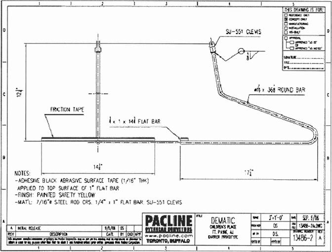
2. This quotation includes 600 single-hook carriers for conveyor “A” and 550 single-hook carriers for conveyor ‘B’. Single-hook carrier type shown on drawing 13486-2 Rev. A. It is assumed that all empty cardboard boxes are conveyable on these carriers, though it is recommended that samples of these cardboard boxes be supplied to Pacline for prototype testing and approval. Any subsequent changes in design may result in a corresponding cost change to be issued to the customer in the form of a “Change Order”.
3. The carriers have been spaced at 4’-0” c-c. The spacing of the carriers and the conveyor speed will affect the throughput of the overhead system.
3.9.2 Mechanical Equipment
1. This is a multiple drive system. Care has been taken to space the drives evenly over the length of the conveyor.
2. Elevation changes of 6 & 30 degrees are included.
3. The drive unit, curves, track clamps and chain will be zinc-plated.
4. This system will operate at a variable speed range of 25 FPM to 50 FPM.
5. The conveyor chain must be properly lubricated in order to avoid premature wear. An automatic lubricator is included. A suitable maintenance schedule outlining chain-oiling intervals should be established.
6. The design of overhead chain conveyors is such that lubricant or debris may fall on products below. This may occur due to over-lubrication or a dusty environment. For this reason, Pacline has included drip trays that will safeguard against contamination of customer products.
3.9.3 Supports
1. This quotation includes floor supports and ceiling supports that consist of beam clamps, sway braces, hanger pipe and all header steel.
2. Floor support locations are for all areas under the mezzanine on the lower level. The conveyor will be supported at an elevation to provide a minimum
39
bottom of carrier height clearance of 6’-0”. The floor supports will typically consist of 3” x 3” H.S.S. posts with 10” x 10” base plates and 3” angle arms painted Pacline Blue.
3. The following assumptions have been made for the ceiling supports any subsequent changes in design may result in a corresponding cost change to be issued to the customer in the form of a “Change Order”:
· Truss spacing of 6’-4”
· Maximum truss height of 35’-6” to underside
· Open web steel joist design
4. Pacline accepts no responsibility for building strength and integrity. Pacline will supply estimated loads and loading points to customer for approval during project engineering.
3.9.4 Safety Guarding
1. Safety guarding is included for all portions of the system above the mezzanine where the bottom of the conveyor track is at 10’- 6” elevation on the 30 deg inclines only. As safety regulations vary with country, region and customer, Pacline accepts no responsibility for meeting safety codes in regard to safety guarding. Changes in design may result in a corresponding cost change to be issued to the customer in the form of a “Change Order”.
2. Safety guarding type to be used is a nylon mesh type.
3.9.5 Installation
1. Non-union mechanical installation is included.
2. The installation will be conducted on regular hours, 7:30 a.m. until 5:30 p.m. with total access to the installation area of the system.
3. Customer to receive the equipment shipped by Pacline to site. This may include awkward items such as standard crates 3’ x 3’ x 11’, floor supports shipped loose, structural steel shipped loose, safety guarding and structural frames shipped loose, etc.
4. Pacline will supply all mobile equipment.
5. Customer to supply power for a Pacline welding machine.
6. 115V power for hand tools and lights must be made available throughout the installation area.
3.9.6 Electrical
1. Non-union electrical installation is included.
2. Electrical wiring of the panel, automatic oiler, motors and any other specified electrical devices is included.
40
3. A single 3’ x 3’ electrical control panel for each system (similar to attached Pacline drawing 13486.E100 Rev. A attached) containing variable speed controllers, disconnect, line/ load reactor, etc., is included.
4. Each drive unit will be equipped with its own variable frequency drive. These VFD’s will be linked to each other to ensure that all four drives are running at the same speed.
5. Each motor will be equipped with a shock relay.
6. Devices and panels will be mounted in the most economical location.
7. The customer will be responsible for bringing 480 V/ 3 PH/ 60 Hz feed power and control signal wires (run/stop) into the single Pacline control cabinet included herein. Pacline’s conveyors will be started and stopped from the main control panel via these wires. Power will be fed to Pacline’s panel from the Roller Conveyor panel. If a roller conveyor e-stop is activated, the power will be dropped to the Pacline panel.
8. This quotation is based on having the feed power and run/ stop signals available at the time of the installation so that Pacline does not have to leave site and return later.
9. E-stops are not provided. The customer will utilize it’s e-stop pullcords and e-stop pushbuttons to drop power to the overhead chain conveyors as required.
10. The Customer will also be responsible for bringing 115/ 1/ 60 feed power (terminated by duplex receptacle) to the lubricator.
11. EMT thinwall conduit is included and will be routed in the most economical way
12. The installation will be conducted on regular hours, 7:30 a.m. until 5:30 p.m. with total access to the installation area of the system.
13. At the time of quoting, an electrical specification was not provided. Pacline reserves the right to re-quote the project if the customer issues an electrical specification prior to, at the time of, or after purchase order issue.
3.9.7 Additional Documents
1. Drawing 13486-Rev. A. – Carrier – Single Hook – (Preliminary)
2. Drawing 13486-E100. Rev. A. – Control Panel
41
42
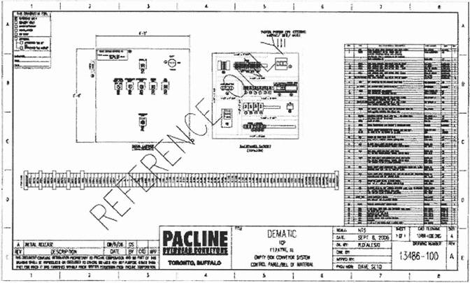
43

Manufacturers of - Mezzanines - Vertical Lifts - - Protective Rail Systems - Custom Steel Fabrication Solutions
The quotation includes the following:
· 5 structures totaling approximately 156,000 square feet.
· 125 PSF plus under hung loads per Andy’s drawings.
· 20 gauge roof deck with Resindek LD with grey finish.
· 50’ x 58’ foot spans to match building columns (PTL structure only).
· 20’ and 25’ spans on balance of structures. Final column layout to be decided by Dematic and Wildeck.
· Kick plate at all edges.
· 42” high guardrail at exposed edges not protected by conveyor.
· 12 sets of stairs to upper structures.
· 6 caged ladders to lower structures.
· All necessary hardware.
· Openings as needed. Locations to be flexible to fit framing and conveyors.
· Footings are by others. Shimming (if required) is by others.
44
4 Controls Resale Equipment Details
4.1.1 Hardware Requirements
The following is a list of hardware components for the GSMi server. Additional hardware may be necessary, depending on the OPC interface to the conveyor controllers (PLCs).
GSMi Server Hardware - minimum requirements |
| Quantity |
Dell Desktop Mini-tower, Pentium IV, 1 GHz computer with 80 GB hard drive, 1GB RAM |
| 1 |
10/100 BaseT Network Interface Card (may be on motherboard) |
| 1 |
19” color monitor |
| 1 |
Modem |
| 1 |
UPS (Un-interruptible Power Supply) |
| 1 |
Surge Suppressor |
| 1 |
GSMi Client (workstation) Hardware - minimum requirements |
| Quantity |
Pentium, with 200 MB free on hard drive, 128 MB RAM |
| 1 |
10/100 BaseT Network Interface Card (may be on motherboard) |
| 1 |
45
4.1.2 Software Requirements
The following is a list of software components for the GSMi server. Additional software may be necessary, depending on the OPC interface to the conveyor controllers (PLCs).
GSMi Server Software - minimum requirements |
| Quantity |
Windows XP Pro |
| 1 |
ICONICS Genesis32 Enterprise Edition |
| 1 |
Control network interface software |
| 1 |
Backup Software |
| 1 |
Antivirus Software |
| 1 |
Remote Support Software |
| 1 |
GSMi Client (workstation) Software - minimum requirements |
| Quantity |
Microsoft® Internet Explorer Version 6.0 or higher |
| 1 |
46

4.2.1 Specifications
4.2.1.1 Bar Code
Codes |
| A |
Symbology |
| Code 128 “C” |
Characters |
| 20 |
Min. Narrow Element |
| .015” |
Max. Wide Element |
| .060” |
Pattern Height |
| 1.38” |
Pattern Length |
| 2.75” |
Print Method |
| Thermal Transfer |
Comments |
| Side/Ladder |
4.2.1.2 Carton Characteristics
· Minimum: 9.0”L x 7.0”W x 4.5”H
· Maximum: 34.0”L x 22.0”W x 16.0”H
4.2.1.3 Material Handling
· Type: Belt
· Width: 30.0”
· Speed: 350-540fpm
· Minimum Product Spacing: 8.0”
· Carton Orientation: non Edge Aligned
4.2.1.4 Scanning System Configuration
· Scanner: Axiom 2L/1M Line Scanner w/DRX
· Near Reading Distance: 22.0”
· Far Reading Distance: 45.0”
47
· Total Depth Of Field: 23.0”
· Scan Window: 22.0” @ 22.0”
4.2.1.5 Scanning System Communications
· Interface: RS-422
· Baud Rate: 9600
· Data Bits: 7
· Stop Bits: 2
· Parity: Odd
· Output Message Configuration: DATA (20) CR
· No-Read Message: 0’s in DATA Field
· Multiple Message: 9’s in DATA Field
· Relay: 1
· Relay Function: No-read
NOTE Multiple Read is identified when there is two (2) bar codes presented during a single read cycle of the same symbology and character length.
48
5.1 SortDirector System Deliverables
5.1.1 Computer Hardware
Qty |
| Description |
2 primary |
| PROLIANT ML370 G4 XEON-DP 3.2G 1GHZ 1MB Cache 1GB Array Rack |
2 back-up |
| PROLIANT ML370 G4 XEON-DP 3.2G 1GHZ 1MB Cache 1GB Array Rack |
2 primary |
| XEON 3.2G/1G 1MB Processor for ML370 G4 |
2 back-up |
| XEON 3.2G/1G 1MB Processor for ML370 G4 |
2 primary |
| 1GB PC2700 DDR SDRAM 1X1GB |
2 back-up |
| 1GB PC2700 DDR SDRAM 1X1GB |
2 primary |
| Wide ULTRA3 PCI Single Channel HD68 PROLIANT SCSI Controller |
2 back-up |
| Wide ULTRA3 PCI Single Channel HD68 PROLIANT SCSI Controller |
2 primary |
| 20/40GB DDS4 DAT40I SCSI U2/LVD 3/6MB |
2 back-up |
| 20/40GB DDS4 DAT40I SCSI U2/LVD 3/6MB |
12 |
| 36GB 15K U320 Pluggable Universal Hard Drive |
1 |
| DC5j000 MT dvd/cdrw |
1 |
| 1.44M Floppy drive |
1 |
| 17 in. LCD Flat Panel Monitor |
1 Lot |
| Connectors, Cables, Switches, etc. |
2 |
| UPS R3000 XR Low Voltage and 6-port serial card |
1 |
| Rack system to contain all computer equipment |
5.1.2 Computer Software
Both vendor supplied software and Dematic supplied software are required for the SortDirector installation. Licenses are required for vendor software and will become the property of The Children’s Place. Dematic will install and verify the vendor supplied software is operational (along with the hardware components for the server computer equipment) before shipping the equipment to The Children’s Place.
49
5.2 Shelf Mounted PickDirector Hardware
The following items are mounted either in the rack structure or on the rack face in the put modules:
Qty |
| Description |
10 |
| NetController Panel / 8 Power Supplies & 4 Converters |
320 |
| BayDisplay |
2640 |
| MaxiPick |
160 |
| ComPort |
83 |
| EndCap (Right Hand) |
83 |
| EndCap (Left Hand) |
40 |
| Terminating Resistor |
5960 ft |
| PowerRail Assembly |
160 |
| Wireless Scanner, Symbol LS3478 with Radio-Charging Cradle and Battery |
40 |
| Symbol 4 Slot Battery Charger with Line cord and Adapter |
5.2.1 Spare PickDirector Hardware
The following items are provided as spares:
Qty |
| Description |
4 |
| Converter |
1 |
| NetController |
8 |
| Power Supply |
32 |
| BayDisplay |
50 |
| MaxiPick |
16 |
| ComPort |
3 |
| EndCap (Right Hand) |
3 |
| EndCap (Left Hand) |
8 |
| Wireless Scanner, Symbol LS3478 with Radio-Charging Cradle and Battery |
8 |
| Wireless Scanner, Symbol LS3478 with Battery Only |
17 |
| Wireless Scanner batteries |
50
1. The mechanical, electrical, controls, and field wiring installation, unless otherwise specified, will be provided by Dematic.
2. Installation is based on utilizing non-union / non-prevailing wage labor on a straight time, first shift basis, with work occurring during normal working hours (8:00 AM to 5:00 PM), Monday through Friday, excluding holidays. If payment of union or prevailing wages is required, the Base System Price will be increased and The Children’s Place will be responsible for the additional charges.
3. The Children’s Place acknowledges that the proposed installation may be performed on a non-union wage basis only if all building tradesmen are absent from the installation site during the period when Dematic’s installation crew or its subcontractors will be on the job site.
4. Dematic will receive, unload, and move the equipment to the assigned storage area (provided by The Children’s Place). The equipment is to be stored within 200 feet of its intended installation location.
5. Dematic will move equipment from storage to the installation area.
6. Installation is to be performed in accordance with the agreed upon Project Schedule. Any delay, acceleration, or other variation in the installation may involve an adjustment to the Sales Agreement price and/or the Schedule.
6.1 Mechanical Installation Practices
Proper mechanical installation is vital for the equipment to operate as described in this Proposal. The following installation standards summarize Dematic installation techniques and procedures for installing material handling equipment. The installation standards show the importance Dematic places on quality installation.
6.1.1 Dimensional Reference Points
A baseline will be established by measuring from the centerline of two building columns, one at each end of the installation site. This will be done in both the north / south, and east / west directions, as agreed upon by The Children’s Place and Dematic. All subsequent centerlines for the conveyor system will be taken from these established baselines. Conveyors will be installed with the centerline of the bed matching the centerline of the conveyor path through the use of a template and plumb line or other acceptable means. All necessary dimensions will be shown on the layout drawings.
51
6.1.2 Elevations
Conveyors will be installed in accordance with the elevation indicated on the Approved layout drawings. After the first elevation is established, the elevation of all other points will be related to this first point. The practice of dimensioning elevations from the floor at each point of support will not be followed. When the floor level changes significantly, such as the system going to an upper or lower floor or into another building or room, a new elevation will be established from the floor at that point. This new elevation will then become the reference for subsequent elevations.
All conveyor beds will be leveled at right angles and in the direction of travel, unless otherwise specified. Conveyor elevations are measured to the top of the conveying surface.
6.1.3 Floor Mounting Conveyor
Anchoring will be accomplished by drilling into the floor and inserting an anchor bolt. Intermediate stands will be anchored with 3/8 inch diameter bolts, one in each support assembly. Support stands for drives will be anchored with 1/2 inch diameter bolts, two per support assembly and four per drive. Explosive type anchors will not be used.
6.1.4 Ceiling Hanging Conveyor
Overhead support will be accomplished by bolted connections. Intermediate structural steel members will be attached to the building structure by approved clamping methods using A325 fasteners. Threaded rod hangers that are 5/8 inch diameter will be provided to suspend the conveyor and components.
6.1.5 Welding
The Children’s Place will permit Dematic and/or Dematic’s subcontractors to weld or flame cut at the installation site as necessary to modify equipment for proper installation. Dematic will conform to all OSHA regulations including “Hot Work” permits if required. Copies of all required permits to be supplied to all parties prior to performance of work noted on such permits.
6.1.6 Field Painting
All exposed field steel supplied by Dematic or its subcontractors, unless otherwise specified, will be touch-up painted to match the painted finish of the equipment (Light grey RAL 7035). This includes hangers, headers, special supports, braces, etc. All painted equipment surfaces altered during the erection process will be touched up in the field.
52
6.2 Electrical Installation Practices
Electrical wiring of the proposed motors and control devices is included in this Proposal.
1. The field wiring installation from the proposed control cabinet(s) to Dematic’s supplied motors and control devices will be provided by Dematic.
2. Dematic will provide wiring from the existing power source (by others) to the proposed control cabinet(s). The Children’s Place is to ensure sufficient capacity is available and provide circuit breakers.
3. The Children’s Place will provide any required interface wiring between the material handling system and equipment provided by others.
Installation of this system will be performed using Dematic standards for electrical installation. A description of Dematic electrical installation standards follows.
Installation will conform to NEC and any local and/or state codes that may apply. All material supplied for field wiring will be UL listed. All field wiring will be verified for proper termination, identification, and operation by employing installation run-in procedures.
6.2.1 Conduit and Wireways
EMT conduit fitting will be of compression type. Galvanized rigid conduit (GRS) will be used where conduit is placed on concrete floors or is subject to physical damage. Conduit and wireway will be run parallel to or perpendicular to the conveyor or building structure. Conduit will be attached to guardrails where applicable. Wireways will be used where large numbers of wires and multiple devices are to be installed. Conduit and wireways will be properly installed, supported, and terminated pursuant to NEC standards.
Conduit installed on or near equipment will not obstruct the movement of product loading and unloading, as it could cause damage to conduit and conduit supports. Conduit will not be attached to the side of picking conveyors, but rather the underside of picking conveyors or racks to avoid damage from product loading/unloading. Conduit on or near equipment will be mounted clear from mechanical and electrical adjustable brackets or hardware.
When flexible conduit is required, liquid tight flexible conduit will be used in lengths not to exceed the minimum needed to allow proper movement. No EMT, GRS, or flexible conduit will be smaller than 1/2 inch trade size. Conduit wire fill will not exceed NEC standards.
Standard wiring harnesses are used to connect the control modules
53
The power harness runs in the lower side channel, the Open Network (LCON) cable runs in the middle of the side channel from control module to control module, and the PROFInet cable runs in the top of the side channel.
The physical separation of the higher voltage power cabling, the LCON, and the Ethernet help reduce Electromagnetic Interface (EMI).
By running industrial cabling in the side channel at the point of manufacture, the need for Electrical Metallic Conduit (EMC) is reduced.
6.2.2 Junction Terminal and Pull Boxes
Pull boxes or fittings will be installed at required intervals and properly supported per NEC. Junction and pull boxes will be of adequate size, pursuant to NEC standards, and will not put pressure on splices and wire insulation when such boxes are closed. A maximum of ten splices will be allowed in a junction box. When more than ten splices are necessary, terminal strips will be provided. Generally, junction boxes will be installed in lieu of conduit fittings, where practical, in order to facilitate future additions and deletions of conduit and devices.
6.2.3 Field Wiring
Color coding of field wiring will be as follows:
Wire Color |
| Description |
Brown, Orange, and Yellow |
| Line and load of 480 AC motor circuits |
Red |
| AC control circuits, 150 volts and below |
Blue |
| DC supply circuits, 150 volts and below |
Blue |
| DC control circuits, 150 volts and below |
Yellow with red stripe |
| Interlock control circuits and wiring from external power sources |
Green |
| Equipment grounding conductors (w/ or w/o yellow tracer) |
White |
| Grounded AC circuit conductors |
Gray |
| Grounded DC circuit conductors |
NOTE Conductors, assigned by numbers, will carry the same color for the entire length of the conductor
· All single conductor control wiring will be #14 THHN or THWN stranded copper wire unless otherwise specified or distributed I/O is utilized
· All motor wiring will be a minimum of #12 THHN or THWN stranded copper wire
54
· All wiring will be increased in size in order to compensate for any voltage drop due to length of the conductors
· Conductors for frequency controlled circuits and clean AC or DC circuits will be isolated from other conductors as prescribed by Dematic Controls Engineering
· A minimum of ten percent spare #14 red control wires will be installed in each main conduit run and between control cabinets and associated consoles
· A minimum of six and a maximum of ten #14 control wires will be installed in each wireway run
· Spare control wires will be labeled with a “Brady Marker” designating control cabinet or console source. (For example cc1-sp1 for spare number 1 originating from control cabinet number 1)
· When three or less conductors are spliced, a “scotchlok” or equivalent wire nut connector may be used if the correct wire nut connector is used for the wire being terminated and a sound termination can be made
· All splices will be marked with printed “Brady Markers” or an equivalent permanent marker with the proper wire number per control drawings
· If “generic” numbers are used for pulling purposes, they will be replaced with the proper wire number per control drawings
· Terminal connections at control devices, control centers, and junction boxes will be marked with “Brady” markers or an equivalent marker
6.2.4 Splicing Requirements
· Splices are not allowed in conduit. Splices are allowed in wireways and wiring troughs only if splices are accessible and made in a manner as to not apply pressure to the termination (that is, a wire nut splice or termination will have adequate slack with preferably a bank of electrical tape or knot tied in order to secure all wires no less than 6 inches from the splice or termination).
· Cable will be run continuously from terminal-to-terminal without splices. Cables will be run in bridle rings when protected by building structures or equipment and will be protected by conduit where subject to physical damage, unless otherwise specified.
6.2.5 Devices
· All limit switches, photo controls, motors, solenoids, or other devices will be attached with liquid tight flexible conduit or cord
· Flexible conduit will not exceed 4 feet – 6 inches in length and will provide for 12 inch adjustment in either direction from original position, per dimensioned control layout drawings
55
· All photoeye, limit switch, solenoid, disconnect switch, and bracket mounted devices will have brackets bolted with hex bolts and nuts of 1/4 inch minimum
· All devices will be adjusted for proper alignment, travel, and/or position and properly tightened to avoid misalignment due to vibration
· All hole-punched or drilled-in conveyor surfaces for photoeyes, reflectors, or any other devices will be filed smooth as to not interfere with product flow
· All field devices will be properly labeled with an assigned control number per schematics unless another type label is specified
· All control and pushbutton stations will be located and properly mounted per layout drawings unless otherwise specified.
· All pull cords will be installed with eyebolts at intervals not exceeding 12 feet and will properly activate the attached limit switch without excessive force
· Slack will be kept to a minimum, still allowing for activation of the switch
· Two cable clamps or Dematic cable terminators are required at each cable termination
· Turnbuckles and/or pulleys will be installed as specified by Dematic System Engineering
56
1. Dematic will receive, unload, and move the equipment to the assigned storage area. The equipment is to be stored near its intended installation location. The space required to adequately store and prepare the equipment for installation will be 20,000 square feet.
2. The Children’s Place will permit Dematic and/or Dematic subcontractors to burn and weld at the installation site.
7.2 The Children’s Place Deliverables
The Children’s Place is responsible for the following:
1. The project coordination involving all contractors employed by The Children’s Place, as required, to help ensure that work is completed in accordance with the project schedule.
2. Any mechanical and electrical interface with peripheral equipment, process control, or process supplies, not specifically included in this Proposal.
3. Supply, install, connect and make operative: Host computer(s), interface and any equipment for the interface, peripherals and system software including field-located devices. Provide any required applications software, including installation, startup, debug, testing, and documentation.
4. Provide the Ethernet LAN and Ethernet LAN drops with appropriate connectors to each Dematic-supplied computer.
5. Dedicated VPN access is to be provided.
6. Two 20 Amp, 120V standard receptacles for the Dematic supplied computer(s) are required. Also, one additional 30 Amp. 120V twist lock plug receptacle on a separate circuit is required for the air conditioning unit, if purchased.
7. 120 Volt convenience outlets for all MHS equipment, computer equipment, and Dematic UPS unit(s).
8. Provide an appropriate operating environment for all computers and components. System components typically require environments as follows:
a. Temperature: 15-32 degrees Centigrade (59-90 degrees Fahrenheit). (Controlled for units in environmental enclosures.)
b. Relative Humidity: Humidity within the range from 20 percent to 80 percent without condensation will enable satisfactory operation of these
57
devices. This is controlled for all units installed in environmental enclosures.
c. Electrical: Input voltage required by the computers is 120V, with a tolerance of 90-130V and a frequency of 50 Hz/60 Hz with a tolerance of 48-62 Hz. Power requirements vary according to the number and types of devices included in the configuration. Considering the normal quality of power available in an industrial facility, a dedicated power regulation transformer is recommended for the computer CPU and disks to attenuate transients and to provide “in spec” power during surges and brown outs.
d. Cleanliness: Although a ‘computer room’ environment is not always required for mini-computers and micro-computers, the location selected for the computer should be reasonably free from grease, dirt, smoke, and other similar air contaminants. Filters for units in environmental enclosures must be maintained.
e. Vibration and Shock: Vibration can slowly impair mechanical parts and, when severe, may cause system errors or disk problems; hence it should be avoided or controlled. The computer equipment is built to withstand normal building vibrations.
However, conditions where vibration is likely, such as a platform where heavy machinery is operating, should be avoided. If unusual or prolonged vibration is likely, as in systems installed in a truck, ship, or aircraft, all cabinets should be securely anchored to the installation deck and/or bulkheads by mounting brackets and shock mounts.
f. Electromagnetic Interference: Introduction of electrical interference can cause errors in computer functions and data. Sources of electromagnetic interference such as radar, radio and television transmission, automotive ignition systems, power lines, electric tools, and appliances will be kept outside of the computer room area.
9. Suitable electric service, lighting, water, and heat as may be required for installation, test, and operation of the equipment, per OSHA specifications. Voltage supplies may not vary more than plus or minus 8 percent during installation and may not vary more than plus or minus 5 percent for permanent power. The frequency variation may not exceed plus or minus 1 percent at all times. Electrical service of 120V, 20 amperes on 100-foot centers and 480V, 3 phase, 100 amperes on 200-foot centers will be required for installation tools. The minimum lighting requirement will be not less that 10 foot candles as measured at the location where the work is actually performed.
10. Full service maintenance of equipment, commencing with The Children’s Place’s operation of a portion or all of the equipment.
11. Full compliance by The Children’s Place with the “OSHA Lockout / Tag out” rules and regulations as enacted by the U.S. Department of Labor.
58
12. Area guarding necessary to protect Personnel such as: warning signs, handrails, barriers, netting, floor markings, etc. will be the responsibility of The Children’s Place.
13. Guarding to protect the equipment from damage by fork trucks.
14. Qualified Operation / Maintenance Technicians, with any tools or equipment required, for full-time on-the-job training commencing at the start of system checkout on-site. Provide qualified, trained Operators in sufficient quantities for system testing.
15. After beneficial use, suitable devices for the safe maintenance or servicing of elevated equipment where catwalks, platforms, or similar means of access are not provided. These devices could include man lifts, platform ladders, or similar devices.
16. Area for tool cribs and construction trailers, and parking for lifting devices.
17. Excavations, drainage, piling, foundations, masonry and concrete work, concrete lining, steel, and other building materials necessary to the installation or operation of the equipment.
18. Any building alterations, including enclosures, floor openings, wall openings, fire doors, structural integrity and similar requirements in accordance with all applicable Federal, State, and Local laws, codes and regulations. This is to include the removal or alteration of obstructions, concrete floor cuts and/or expansion joints, existing equipment or new equipment not provided by Dematic to allow for a clear path for the installation of the equipment listed in this Proposal and depicted on the layout drawings provided. In the event Dematic is required to alter the path of the proposed system or perform other work to accommodate the building alterations or obstructions, the price and schedule impacts will be provided to The Children’s Place for review and approval.
19. Building ground and lightning protection systems.
20. All fire protection system requirements.
21. Drain lines will be provided as required for air compressor(s) and air dryer(s).
22. Appropriate Operational and Maintenance Personnel to receive on-the-job operational and maintenance instructions from Dematic prior to completion of the work required by this Proposal.
23. Security services and/or precautions sufficient to protect the worksite, construction underway, and Dematic tools/equipment.
24. Secure storage for backup media.
7.3 The Children’s Place Site Conditions
The Children’s Place is responsible for the following:
59
1. A building with adequate structural strength to support the load of the equipment, materials being handled, guarding, and all other loads being imposed upon the structure in accordance with all applicable federal, state and local laws, codes and regulations.
2. A worksite prepared to permit lay down, installation, and operation of the equipment in a time frame as required by the project schedule.
3. A worksite in a watertight condition and free of debris or obstructions other than those caused by Dematic.
4. A work site to permit installation and operation of the equipment, as required by the Project Schedule.
5. A clear path for the ingress to and the egress from the installation site for Dematic Personnel and equipment.
6. The necessary access roads and cleared dock areas suitable for receiving and unloading the equipment. Dematic will advise the approximate arrival time of delivery trucks.
7. Unless otherwise agreed to, an open and clear area above and below the equipment to be installed overhead.
8. A secure, safe, dry, convenient, and adequate storage area for Dematic equipment, tools, and materials used on the site. Adequate working space will also be provided for the Dematic Installation crew.
9. Flooring with anti-static qualities needs to be provided in the computer room area.
60
8.1 Mutual Commitment to Safety
Dematic and The Children’s Place recognize that accidents can be reduced by following safe practices in the design, construction, installation, operation, and maintenance of the equipment. Therefore, in a mutual effort to minimize the possibility of accidents, Dematic and The Children’s Place agree as follows:
1. Dematic furnished equipment will be designed, manufactured, and installed under the guidance of the appropriate ANSI/ASME Standards. Likewise, The Children’s Place will apply appropriate ANSI/ASME Standards as they incorporate user instructions into their operations, and will enforce these operating standards and instructions. In particular, The Children’s Place will place into standard operating procedure those instructions contained within the Dematic supplied Conveyor Safety Guidelines Form Number 5100 (9/02).
2. When Dematic provides on-site installation services, Dematic will provide operational and maintenance instructions and training prior to the completion of Commissioning. The Children’s Place will provide the appropriate Operational and Maintenance Personnel for such instructions and training. The Children’s Place will retain a record of attendees.
3. Dematic will provide written instructions relating to the safe use of the equipment. These materials will include such items as manuals, safety instructions, posters, user instructions, etc. The Children’s Place will make such instructions available on a continuous basis to its Operational and Maintenance Personnel.
4. The Children’s Place will periodically conduct safety programs, as required, to keep its Operational and Maintenance Personnel, including new hires, constantly knowledgeable with respect to the safe use of the equipment.
5. The Children’s Place will maintain a dress code which requires all Personnel around the equipment to wear hair protection (or short hair), snug fitting clothes and heavy duty work shoes. The wearing of tennis shoes, baggy cuffs, neckties, jewelry and similar apparel will not be permitted. Hard hats will be worn where Personnel could be subjected to injury because of obstructions or falling objects.
6. The Children’s Place will provide man lifts, platforms or similar devices for the safe maintenance servicing of elevated equipment where catwalks, platforms or similar means of access are not provided.
61
8.2 OSHA Lockout / Tagout Rules
NOTE An important note to The Children’s Place.
On August 28, 1989, the U.S. Department of Labor amended the Occupational Safety and Health Standards to incorporate lockout / tagout requirements. This standard applies to most employers and covers, among other things, “the servicing and maintenance of machines and equipment in which the unexpected energization or start-up of the machines or equipment…could cause injury to employee.” The standard states that servicing and maintenance covers various workplace activities including “lubrication, cleaning or un-jamming of machines or equipment...where the employee may be exposed to the unexpected energization or start-up of the equipment….”
In Dematic’s opinion, this standard applies to most workplaces utilizing powered conveyor. Dematic is bringing this to the attention of The Children’s Place in the event The Children’s Place is not aware of the standard. Dematic urges The Children’s Place to review the applicability and requirements of the standard with respect to The Children’s Place’s facilities. In general, the standard requires employers to establish an ongoing program of control procedures and employee training (regardless of training provided by the equipment vendor at the time of sale) to ensure that equipment is rendered inoperative before any servicing or maintenance is performed.
The referenced standard (as may be amended) can be found at 29 CFR Part 1910, Section 1910.147; it was published in the Federal Register, Volume 54, No. 169 on September 1, 1989. Also, copies may be requested from the Dematic Contracts Administration Department. This and other pertinent OSHA safety standards may be found at WWW.osha.gov.
62
The following prices are provided for the Third-party commodities, Mechanical Installation, and Electrical Installation services as described in Dematic Proposal 104846. The prices and the acceptance of this Agreement by Dematic are contingent upon performing the work under Proposal 104846 in conjunction with the Dematic Proposal Number 103522 dated 2006-September-27 and execution by The Children’s Place Services Company, LLC (“The Children’s Place”) of the Agreement for Dematic Proposal Number 103522 dated 2006-September-27.
The price for the performance of Dematic work described in this Proposal is as follows:
Base System Price | Total |
| $ | 16,756.000 |
|
Above pricing does not include building permits, installation permits, or other project permits or fees. All permits and fees are the responsibility of The Children’s Place.
All options are priced to be purchased with the Base System.
Above pricing does not include any sales, use, excise, or similar taxes – these are the responsibility of The Children’s Place. If The Children’s Place is tax exempt, an appropriate tax exemption certificate must be provided within 60 days of order.
Notwithstanding any of the above, within thirty (30) days of signing the Agreement the Purchaser shall have the right to terminate the Agreement upon written notice to Dematic. In the event of such termination, Purchaser shall pay Dematic the reasonable value of the equipment and services already provided to Purchaser.
All prices are in U.S. dollars.
NOTE Commodity Pricing Fluctuations – The metals (steel, aluminum, and copper) to be provided for this project were priced at rates in effect as of the date of this Proposal. Because of the volatility of market prices, any changes in the prices for these commodities from the date of this Proposal to the date on which Dematic ships the equipment, will be charged at “price in effect” on the date of
63
shipment to the installation site. Price adjustments shall be made based upon the changes in the following published price indicators: (1) Steel - Nucor Steel’s price list and surcharges, (2) Aluminum — London Metal Exchange, (3) Copper-London Metal Exchange, which may result in an added charge or credit to The Children’s Place.
9.3 Delivery and Shipping Terms
Delivery and Shipping Terms for the equipment shall be: F.O.B. Destination, Freight Prepay and Add.
9.4 Export Laws and Regulations
The Children’s Place acknowledges that Dematic is required to comply with applicable export laws and regulations relating to the sale, exportation, transfer, assignment, disposal and usage of the work/equipment/services provided under the Contract, including any export license requirements. The Children’s Place agrees that such work/equipment/services shall not at any time directly or indirectly be used, exported, sold, transferred, assigned or otherwise disposed of in a manner which will result in non-compliance with such applicable export laws and regulations. It shall be a condition of the continuing performance by Dematic of its obligations hereunder that compliance with such export laws and regulations be maintained at all times.
The Children’s Place agrees to indemnify and hold Dematic harmless from any and all costs, liabilities, penalties, sanctions and fines related to non-compliance with applicable export laws and regulations that are caused by The Children’s Place’s negligent actions.
Dematic agrees to submit invoices and The Children’s Place agrees to pay invoices in accordance with the invoice and payment schedule shown below. All payments shall be made payable net 30 days from invoice date, at the address indicated on the Dematic invoice.
A late payment charge of five one-hundredths of one percent (.05) per day (18 percent annum, based upon a 360-day year) will be added to any amount not received by Dematic on or before the invoice payment date indicated on the payment schedule. Where this rate exceeds a maximum rate permitted by applicable law, the permissible rate will apply.
If this Agreement provides for Dematic to install the Equipment, the final invoice, per the invoice and payment schedule, may be held by The Children’s Place as retainer. The Children’s Place will pay the retainer (final invoice) amount within thirty (30) days after Dematic completion of Installation Commissioning.
64
However, should there be a dispute about the completion of the Installation Commissioning, then The Children’s Place shall inform Dematic of any claimed defects in the Equipment and the amount of any retainer necessary to correct claimed defects will be mutually determined. The Children’s Place will then pay the final invoice less the determined amount. The Children’s Place will pay the remaining retainer upon correction by Dematic of any defects in the Equipment as mutually determined.
Upon contract ratification, the following payment terms apply:
Item |
| Payment Terms |
| Time Frame |
1 |
| Twenty percent of the total project price as a down payment less any previous payments made |
| Upon execution of contract. |
2 |
| Monthly progress payments. (Progress payments and down payment will not exceed 50% of the contract value prior to February 1, 2007.) |
| Net thirty days. |
3 |
| Five percent retainer |
| Thirty days after system acceptance. |
This Proposal is based on General Terms and Conditions - - Exhibit A. Dematic’s price is based on our standard practices, equipment, Terms and Conditions, and warranty.
65
This Sales Agreement, (hereinafter referred to as “Agreement”), made by and between The Children’s Place Services Company, LLC, 915 Secaucus Road, Secaucus, New Jersey 07094, (hereinafter referred to as “The Children’s Place”) and Dematic Corp., with headquarters located at 507 Plymouth Avenue, N.E., Grand Rapids, Michigan, 49605, (hereinafter referred to as “Dematic”), constitutes the Agreement of the parties as follows:
1. Dematic agrees to sell to The Children’s Place and The Children’s Place agrees to purchase from Dematic, the equipment and services described in Dematic Proposal Number 104846, dated 2006-September-27, Sections 1 through 10, for the price set forth in the Proposal and on the General Terms and Conditions — Exhibit A.
2. This Agreement constitutes the entire agreement between the parties and no oral or other representation shall prevail, notwithstanding any other terms and conditions of any order submitted by The Children’s Place. Any changes, modifications, or additions to this Agreement are binding and enforceable only if made in writing and signed by both parties.
Approved and Executed By: |
|
|
|
|
|
The Children’s Place Services |
| Dematic Corp. |
|
|
|
|
|
|
/s/ Sal Pepitone |
| /s/ Illegible |
Signature |
| Signature |
|
|
|
SAL PEPITONE |
| [Illegible] |
Name (please print) |
| Name (please print) |
|
|
|
V. P. of LOGISTICS |
| V P SALES |
Title |
| Title |
|
|
|
|
|
|
9-29-06 |
| 9/29/06 |
Date |
| Date |
66
10.1 General Terms and Conditions – Exhibit A
The Dematic Corp. (“Dematic”) Proposal and Sales Agreement specifically incorporate the following General Terms and Conditions. Collectively the Proposal, Sales Agreement, and these General Terms and Conditions are referred to herein as the “Agreement” between Dematic and The Children’s Place.
67
GENERAL TERMS AND CONDITIONS | Exhibit A |
The following General Terms and Conditions shall apply to any resulting order between Dematic Corp. (hereinafter referred to as “Dematic”) and Purchaser.
1. TAXES: Unless otherwise indicated, the price does not include any sales, use, excise, or similar taxes, and Purchaser shall be responsible for all such taxes, whether or not invoiced by Dematic. If taxes are included as part of the price and the rate or base of the tax is increased or decreased, Purchaser will pay any increased taxes, and Dematic will give credit for any tax decrease. Absent written agreement to the contrary, Dematic will pay the tax and be reimbursed by the Purchaser.
In the event Purchaser is exempt from such taxes or should Purchaser elect to pay such taxes directly to the taxing authority, then within 60 days of the order, Purchaser will provide Dematic with a valid tax exemption certificate or similar document satisfactory in form to Dematic.
2. WARRANTY: Dematic warrants that goods sold by Dematic will be free from defects in material and workmanship for a period of two years from the date of installation or four thousand hours of operation, whichever occurs first. Dematic’s obligation under this warranty is limited to repairing or replacing, at Dematic’s option, F.O.B. manufacturing plant, any part of the goods found to be defective within the warranty period. This obligation is conditioned upon receipt by Dematic of prompt written notice of the claimed defect, including a description of the defect and its discovery, and the opportunity for Dematic to inspect the goods in the purchaser’s facility. This obligation does not include costs of labor or other charges incurred in removing or reinstalling parts, and does not apply to goods damaged by misuse, neglect or accident or to goods which have been improperly applied, installed, adjusted, operated, maintained, repaired or altered by persons other than Dematic.
If the goods include computer hardware or software acquired from original manufacturers, Dematic’s obligation will be limited to conveying and transferring to Purchaser any interest, rights and/or warranties which Dematic may obtain.
DEMATIC MAKES NO ADDITIONAL WARRANTIES, EXPRESS OR IMPLED, AS TO ANY GOODS, AND IN PARTICULAR DEMATIC MAKES NO WARRANTIES OF MERCHANTABILITY OR FITNESS FOR ANY PARTICULAR PURPOSE.
3. INSURANCE BY DEMATIC: Dematic will maintain insurance covering its operations as follows:
a. Worker’s Compensation Insurance as required by the state having jurisdiction over Dematic and Employer’s Liability with limit of $1,000,000.
b. Commercial General Liability Insurance with combined single limit for bodily injuries and property damage of $1,000,000.
c. Automotive Liability Insurance for bodily injuries, including death and property damage with combined single limit of $1,000,000.
Dematic may, at its sole option, satisfy these requirements with commercial insurance or through a program of combined self-insurance, self-insured retention, and excess insurance.
Certificates of insurance or letter of authority to self-insure will be furnished upon request.
4. INSURANCE BY PURCHASER: Purchaser assumes all risk of loss from damage and destruction of the material and equipment and any applicable installation charges thereof. Such risk of loss will transfer to Purchaser at the F.O.B. point pursuant to the shipping terms of the Agreement (F.O.B. destination). Purchaser agrees to acquire and maintain all risk insurance covering damage and destruction of the materials and equipment at replacement value and in no event less than the purchase price including any increases by change order(s). The insurance policy or policies shall include Dematic as an insured, shall provide for 20 days prior notification to Dematic if the insurance coverage is terminated, reduced, or otherwise materially modified, and shall provide that the insurance proceeds shall be payable to Dematic and Purchaser as their interests may appear. Payments made by an insurance carrier to Dematic as a result of such damage or destruction of the equipment will be applied against the purchase price and any other amounts owed by Purchaser under the Agreement. Purchaser shall furnish Dematic with certificates evidencing such insurance.
5. INDEMNIFICATION: The equipment furnished hereunder will be manufactured with Dematic safety features and furnished with user safety instructions. The operation of the equipment with safety features removed or modified and/or the disregard of the user safety instructions is outside of Dematic’s control and is the responsibility of the Purchaser. Therefore, Purchaser agrees to indemnify and hold Dematic harmless from any and all claims, demands, liabilities, causes of action, suits, costs, and expenses of any kind or nature (including attorney’s fees) for loss or damage which may be suffered by Dematic as a result of injury to persons arising from such removal or modification to Dematic-furnished safety features and/or the disregard of Dematic-furnished user safety instructions, including any person injured while riding, sitting, stepping, walking, or climbing on the equipment furnished hereunder; Provided that Dematic notifies Purchaser in writing, within 30 days of Dematic’s knowledge of any such claim, and gives Purchaser the exclusive control of the defense and settlement of any claim.
Dematic agrees to indemnify and hold Purchaser harmless from any and all claims, demands, liabilities, causes of action, suits, costs, and expenses of any kind or nature including attorney’s fees) for loss or damage which may be suffered by Purchaser as a result of injury to persons arising from defects in material and workmanship of the equipment caused by Dematic. Provided that Purchaser notifies Dematic in writing, within 30 days of Purchaser’s knowledge of any such claim, and gives Dematic the exclusive control of the defense and settlement of any claim.
6. CHANGE ORDER: The parties may agree at any time prior to final payment of the Agreement to make additions, deletions, or other revisions by Change Order or Work Order (as defined below) without invalidating the Agreement. No such change will be performed by Dematic until an approved Change Order or Work Order is executed as provided below.
a. When the price, schedule and other conditions relating to the change can be determined prior to the start of work under the change, a document describing this change (Change Order) will be issued for execution by the parties.
b. When the change requires immediate action and the issuance of an executed Change Order with firm price would unreasonably delay the change. Purchaser shall place its signature upon a document authorizing Dematic to proceed
with the change (Work Order). After the change under the Work Order has been completed, Dematic will calculate the firm price for the change using actual costs (including overhead and reasonable profit) current at time of performance of the
work. Completed Work Order(s) will be incorporated into a Change Order for execution by the parties.
Unless expressly modified by a Change Order or Work Order, the provisions of the Agreement will govern all work performed under such Change Order or Work Order.
7. LIENS: Dematic will protect Purchaser as to any lien asserted against Purchaser’s property for work, material or services furnished by others at Dematic’s request when Purchaser makes the payments provided for in the Agreement.
8. RIGHTS AND REMEDIES: If Dematic defaults in the performance of any of its obligations under the Agreement (other than its obligations under Article 2 hereof) and if Dematic has not cured the default or implemented a plan to cure the default in a diligent manner within 20 days after Purchaser shall have given Dematic written notice of the default, or such other time period as mutually agreed upon, Purchaser shall have the right to terminate the Agreement upon written notice to Dematic. In the event of such termination, Purchaser may (i) pay to Dematic the reasonable value of equipment and services already provided to Purchaser, or (ii) complete the work specified in the Agreement.
If Purchaser elects to complete the work and the reasonable costs of completion exceed the unpaid balance of the Agreement price, Dematic shall pay the difference to Purchaser. If the unpaid balance of the purchase price exceeds the reasonable cost of completion, Purchaser shall pay the difference to Dematic.
If Purchaser fails to pay the purchase price, or any installment thereof, within 10 days after it is due, or if Purchaser defaults in the performance of any of its other obligations under the Agreement and if the default continues for 20 days after Dematic gives Purchaser written notice thereof, or such other time period as mutually agreed upon, then Dematic shall have the right to (i) suspend performance of its obligation under the Agreement until the default is cured, or (ii) exercise any right or remedy provided for in the Agreement, or available to Dematic under applicable law.
9. SECURITY INTEREST AND TITLE:
a. Subject to any interest that Wells Fargo Retail Finance, LLC has in the equipment pursuant to the credit facility dated November 21, 2004, as amended between the purchaser and Wells Fargo, Dematic retains a security interest in the equipment to secure the purchase price payable by Purchaser under the Agreement and all other amounts now and hereafter owing by Purchaser to Dematic hereunder. Upon request by Dematic, Purchaser will execute and deliver to Dematic a financing statement evidencing this security interest.
b. Dematic hereby grants Purchaser a single site non-transferable and non-exclusive license to use all computer software manufactured and provided by Dematic under the Agreement. Title to the software and documentation, if any, provided hereunder shall at all times remain with Dematic. Purchaser agrees to use such software strictly in compliance with the terms of the Agreement, and for the use(s) contemplated herein, and specifically agrees not to copy, furnish, disclose, or otherwise make said software, or any portion thereof, available to any third party.
c. The Dematic manufactured and provided software is a proprietary trade secret of Dematic. Purchaser agrees to maintain confidentiality of Dematic software, and to restrict access to Purchaser’s employees or agents directly concerned with Purchaser’s licensed use of same.
d. Refer to Article 2 for provisions of title for software which Dematic acquires from original manufacturers.
10. DELAYS: If Dematic’s performance is delayed or prevented by Purchaser or other cause uncontrolled by Dematic (such as casualty, labor trouble, governmental action, inability to obtain supplies or transportation, or any order modification by Purchaser):
a. Purchaser agrees to pay Dematic Invoices upon notification that equipment is ready for shipment in accordance with the shipping schedule and to reimburse Dematic for expenses incident to such delay including, without limitation, the cost of engineering, equipment and installation escalations; maintaining, repairing and refurbishing equipment; storage, demurrage, and pullout charges from installation site; and
b. The time for delivery of the equipment and performance of the services will be extended accordingly, and Dematic will not be liable for any damages caused by the delay; and
c. The stated purchase price shall be revised based upon labor wage rates and other conditions prevailing at the time of actual performance.
11. PATENTS: Dematic agrees to indemnify and hold Purchaser harmless from any damages (including litigation costs incurred) that may be awarded against Purchaser in any final judgment based upon a claim that the equipment or its use infringes any currently existing United States patents owned by third parties, provided that Purchaser notifies Dematic in writing, within 30 days of Purchaser’s knowledge of any such claim, and gives Dematic the exclusive control of the defense and settlement of any claim, including the right to make changes in the equipment to avoid any alleged infringement, so long as such changes do not materially affect the performance of such equipment which shall be determined by the Purchaser in its sole reasonable discretion. Purchaser is responsible for any infringement claim arising from any modifications of the equipment by Purchaser or any combining by Purchaser of the equipment with other equipment not furnished by Dematic.
12. ASSIGNMENT/SUBCONTRACTS: Purchaser shall not delegate the performance of any obligation hereunder, nor assign any rights arising under the Agreement, to any unaffiliated third person without the prior written consent of Dematic.
Dematic reserves the right to use subcontractors in the performance of any services to be performed by Dematic. Dematic is responsible for the acts and omissions of any subcontractor so engaged.
13. LIMITATION OF REMEDIES/GOVERNING LAW: The Agreement sets forth Purchaser’s sole and exclusive remedies for any defect in or non-conformity of any equipment or services and for any negligent design, manufacture, or installation of the equipment, and for any breach of the Agreement by Dematic. Neither Dematic nor Purchaser shall be liable for incidental or consequential damages (including loss of profits).
The Agreement shall be interpreted and enforced in accordance with the substantive laws of the State of Michigan.