Exhibit 4.8.49 - Self-Control Components - SQX Series

4573
SQS35...
SQS65...
SQS85...
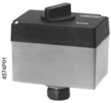
Electrically Operated Valve Actuator
Stroke 5.5mm
 |  | |
| SQS35.50, SQS35.53 | SQS35.00, SQS35.03, SQS65, SQS65.2 | |
| SQS65.5 | SQS85.00, SQS85.03 | |
| With spring-return/ | without spring-return/ | |
| Without manual adjustment | with manual adjustment |
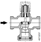
Electrically Operated Valve (EOV)
| l | SQS35…AC 220V working voltage, receiving three-position control signal |
| l | SQS85…AC 24V working voltage, receiving three-position control signal |
| l | SQS65…AC 24V working voltage, receiving DC 0…10V or DC 2…10V control signal |
| l | Adjustment power can reach 400N |
| l | 0.5mm Stroke |
| l | Directly installing onto valve body without other facility |
| l | SQS35.00, SQS35.03, SQS85.00 and SQS85.03 have additional auxiliary switch function |
| l | meeting Standard of DIN 32 730, the actuator with/without spring return |
| l | Actuator without spring return has functions of manual adjustment and position display |
| l | Spring-return actuator with function of position display but without manual adjustment |
Usage
Valve actuator is used for serial types of two-way valve, three-way valve, VVG44…,VVG45…,VVP45…, VMP43…, VMP44…, VMP45…, VXG44…, VXP45… and VV152…, and the drive stoke is 5.5mm.
| Siemens Building Technologies | |
| HVAC Products | CM1N4573C/03.2003 |
| l | Applicable area adheres to IEC 721-3-3 (Regulation 721-3-3 by International Electro-technical Commission ) Grade 3K5 |
| l | Environmental temperature: -5…+50°C |
| l | Valve inner medium temperature: +2…+130°C |
| l | Using installation fittings ASK30 can drive the following 4mm or 5.5mm turn valves: X3i…, WG45…, VXG45…, VXG46… and VVI51… |
Function Three-position or ratio control signal
Revisable synchro motor adopts three-way control signals (SQS35 and SQS85) or ratio control signal DC 0…10V (SQS65 and SQS65.5) or DC 2…10V (SQS65.2) for driving. It makes corresponding valve way through anti-lock gear mechanism.
Three-position control of Terminal Y1or Y2:
| l | Y1 has voltage: valve rod contracts and valve gate opens |
| l | Y2 has voltage: valve rod extends and valve gate closes |
| l | Y1 or Y2 has no voltage: valve rod keeps in current position |
SQS65… Flow Characteristics Selection
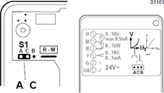
Repositioning connection S1 (under cap/under print circuit board) can change the flow characteristics of 5.5mm turn valve (from “equal proportion” to “linear”). In any case, flow characteristics relate to valve way.
| l | S1 connecting A and C can produce equal-proportion flow characteristics (factory set), which is mainly used for heating application. |
| l | S1 connecting B and C can produce linear flow characteristics, which is mainly used for cooling application. |
| l | For automatic operation, S1 connecting A and C or connecting B and C mainly depends on necessary flow characteristic. |
| S1 Position | ||
S1 connect to: A & C | S1 connect to: B & C | |
| (equal-proportion flow characteristics) | (Linear flow characteristics) | |
 |  |
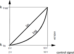
Flow Characteristics
Relationship between DC 0…10V or DC 2…10V control signal and volume flow control signal:
Y= DC 0…10V or DC 2…10V
R=0…1000Ω
| Siemens Building Technologies | |
| HVAC Products | CM1N4573C/03.2003 |
Flow Characteristics
Log=equal=proportion valve characteristics (factory set)
Lin-linear valve characteristics
Flow range
K&100=volume flow 100%
K&=volume flow 0%
Volume flow
Type Overview
| Type No. | Working Voltage | Control Mode (Control Signal) | Runtime (Sec) | Spring-return Function | Spring-return Time(Sec) |
| SQS35.00 | AC 230 V | Three-way | 150 | With | — |
| SQS35.03 | 35 | ||||
| SQS35.50 | 150 | Without | 8 | ||
| SQS35.53 | 35 | ||||
| SQS65.5 | AC 24 V | DC 0…10 V | 35 | with | 8 |
| SQS65 | without | — | |||
| SQS65.2 | DC 2…10 V | ||||
| SQS85.00 | Three-way | 150 | |||
| SQS85.03 | 35 |
Accessory
| Name | Type No. | Applicative Actuator | Used Space |
| Auxiliary Switch | ASC9.6 | SQS35.00,SQS35.03 SQS85.00,SQS85.03 | 1 x ASC9.6 |
Order
Please indicate quality, product name, type No. and accessory when ordering goods.
e.g.: 1 actuator, Type No. SQS35.00, 1 auxiliary switch, Type No. ASC9.6
| Siemens Building Technologies | |
| HVAC Products | CM1N4573C/03.2003 |
Transportation
Actuator, valve and accessory are packed separately and not put together before dispatch.
Capability
The following 5.5mm return, thread two-way and three-way valve can be driven by electric actuators SQS35…, SQS65… and SQS85….
| Type No. | DN[mm] | PN[Bar] | Technical Material |
| Two-way valve | |||
VVG44… VVP45… VMP43…(2) VMP44…(2) VVG55… VVI52… | 15…40 10…20 15, 20 15, 20 15…25 15 | 16 16 16 16 25 25 | N4364 N4845 N4841 N4844 N4379 N4377 |
| Three-way valve | |||
VXG44… VXP45…. XMP43… | 15…40 10…20 15, 20 | 16 16 16 | N4464 N4845 N4841 |
| Three-way valve with T bypass | |||
VMP45… VMP43…(4) VMP44…(4) | 10…20 15, 20 15, 20 | 16 16 16 | N4845 N4841 N4844 |
Allowable pressure differentials of valve ΔPmax and ΔPa are listed in relevant valve technical material data sheet.
Machine Design
| l | Electric actuator, maintenance free |
| l | Reversible synchro motor |
| l | Anti-lock gear mechanism |
| l | SQS35.50, SQS35.53 and SQS65.5 meet spring-return function of DIN 32730 Standard |
| l | Load switch is on stroke limit |
| l | Optional flow characteristics: It is equal-proportion or linear when SQS65… actuator connects valve type WG44…, VVI52… and VXG44… |
| l | Direct-pressure manual adjustment is used for all actuators without spring return: SQS35.00, SQS35.03, SQS65, SQS65.2 AND SQS85… |
| l | All actuators SQS35…, SQS65… AND SQS85… have position indicators |
| l | Auxiliary switch Type No. ASC9.6 applies to actuators SQS35.00, SQS35.03, SQS85.00 AND SQS85.03. Actuator Type No. SQS65.50 and SQS35.53 installs auxiliary switch witin the standard (not ASC9.6) |
| Siemens Building Technologies | |
| HVAC Products | CM1N4573C/03.2003 |
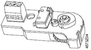
Manual Adjustment
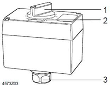
SQS35.00, SQS35.03
SQS65, SQS65.2
SQS85…
| 1. | Manual adjustment |
| 2. | Position indicator |
| 3. | Connecting bolt of valve neck |
Terminal Strip and Auxiliary Switch, etc
 | 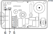 | |
| SQS35…, SQS85… | SQS65… | |
| 5 terminal Strip | 5 terminal Strip | |
| 6 auxiliary switch of SQS35.50 and | 6 《lin》/《log》connection | |
| SQS35.53 within the standard | 7 electrical bridge |
| Accessory | ASC9.6 auxiliary switch |
| Applying to actuators with Type No.SQS35.00, SQS35.03, SQS85.00 and SQS85.03 | |
| Switching point can be adjusted in the stroke range of 0…100% | |
| Prefer “Technical Data” for accessory detail | |
| Disposal | actuator must be splitted into constructional elements before disposal. |
| Project | Actuator must be install electrical connection according to local regulations and connection diagram |
| Siemens Building Technologies | |
| HVAC Products | CM1N4573C/03.2003 |
 Notes: Notes: | It must adhere to regulations and requirements for personal and property safety at any time. |
| SQS65… | When using Actuator SQS65…, valves with Types VVG55…, VMP…, VVP… and VXP… must be connected onto “lin” for connectors of selected flow characteristics. |
| It must obey allowable temperature (see “Application” and “technical Data”). It must be illustrated in Facility Diagram if auxiliary switch is needed. |
Direction

| Valve Installation Handbook is printed on the back of actuator. Accessory Guide is put in corresponding accessory package box. | |
| Debugging | Connection and function is inspected when debugging, in addition, auxiliary or auxiliary switch are also inspected and set necessarily. |
 |  |
Stroke《0》= valve door close | Stoke 《1》=valve door open |
Manual Regulator: Manual regulator is rotated clockwise to close Siemens 5.5mm Stroke Valve (=0% stroke) | |
| SQS35…/SQS85… | The flow characteristics of these actuators are linear when connecting to Valves of Type No. VVG44…, VVI52… or VXG444… |
| SQS65… | The flow characteristics of these actuators are equal-proportion (factory sets) by electrical assembly when connecting to Valves of Type No. VVG44…, VVI52… or VXG44…. The flow characteristics can turn to “linear” through relocating connectors. |
| Siemens Building Technologies | |
| HVAC Products | CM1N4573C/03.2003 |
| Guarantee | Actuator Technical Date (Δpmax, ΔPs, leak rate, noise level and working life) apply to Siemens valves listed in matched “Compatibility” only. |
| Siemens neither guarantee nor promise if SQS… actuators are connected to third-party valve doors. | |
| Maintain | When repairing valves: turn off pump and power source, turn off main stop valve on pipes, release pressure in pipes and cool it down completely. If necessary, electrical connection from terminal should be disconnected. |
| Actuator must be installed correctly with valve door, then restarting can be done. |
Technical Data
Power Source
Working Voltage
| SQS35… | AC230 V ± 15%, 50 / 60 Hz |
| SQS65… | AC 24 V ± 20%, 50 / 60 Hz |
| SQS85… | AC24 V ± 20%, 50 / 60 Hz |
Power consumption
| SQS35.00 | 2.5 VA |
| SQS35.03 | 3.5 VA |
| SQS35.50 | 5 VA |
| SQS35.53 | 6 VA |
| SQS65, SQS65.2 | 4.5 VA |
| SQS65.5 | 7 VA |
| SQS85.00 | 2 VA |
| SQS85.03 | 2 VA |
Limiting converting volume of converting terminal 11 or 12
| SQS35…, SQS85… | AC 250 V, 6A resistance/2.5A inductance |
| Working Parameter | ||
| Control Pattern (Control Signal) | ||
| SQS85… | three-position | |
| SQS65, SQS65.5 | DC 0…10V (in proportion) | |
| SQS65.2 | DC 210V (in proportion) | |
| Runtime | On or Off | |
| SQS35.00, SQS35.50, SQS85.00 | 50Hz, 150 s | |
| SQS35.03, SQS35.53, SQS85.03 | 50Hz, 35 s | |
| SQS65, SQS65.2, SQS65.5 | 50Hz, 35 s |
| Siemens Building Technologies | |
| HVAC Products | CM1N4573C/03.2003 |
| Spring Return Characteristics | ||
| SQS35.50, SQS35.53, SQS65.5 | turn-off time 8 s | |
| Adjustment Force | 400 N | |
| Stroke | 5.5 mm | |
| Input Signal | ||
| Terminal Y (SQS65, SQS65.5) | DC 0…10V, Max 0.1 mA | |
| Terminal Y (SQS65.2) | DC 2…10V, Max 0.1 mA | |
| Terminal R (SQS65, SQS65.5, SQS65.2) | resistance 0…1000Ω | |
| Output Signal | ||
| Terminal U (SQS65, SQS65.5, SQS65.2) | DC 0…10V, Max 0.5 mA | |
| Enclosure Protection Standard | ||
| Enclosure Protection Standard | EN 60529, IP54 | |
| Cable bushing | Pg11 (2x) | |
| Environment Condition | ||
| Valve inner medium temperature | +2…+130°C | |
| Operation | IEC 721-3-3 | |
| Environmental Condition | Grade 3K5 | |
| Temperature | -5…+50°C | |
| Humidity | 5~95%rh | |
| Transportation | IEC 721-2-3 | |
| Environmental Condition | Grade 2K3 | |
| Temperature | -25…+70°C | |
| Humidity | <95%rh | |
| Storage | IEC 721-1-3 | |
| Environmental Condition | Grade 1K3 | |
| Temperature | -5…+50°C | |
| Humidity | 5~95%rh | |
| Industrial Standard | ||
| Meeting CE Authentication: | ||
| EMC directive | 89/336/EEC | |
| Low voltage directive | 73/23/EEC | |
| Size/Weight | ||
| Size | see “Size” |
| Siemens Building Technologies | |
| HVAC Products | CM1N4573C/03.2003 |
| Weight | ||
| SQS35.00, SQS35.03, SQS65, SQS65.2 | ||
| SQS85.00, SQS85.03 | ||
| Packing not included | 0.5kg | |
| Packing included | 0.6kg | |
| SQS35.50, SQ35.53, SQS65.5 | ||
| Packing not included | 0.6kg | |
| Packing included | 0.7kg | |
| Material | ||
| Actuator Shell | plastic | |
| Luifel & manual regulator | plastic | |
| Coupling wheel chain & lever | platic |
Accessory
| ASC9.6 auxiliary contact capacity of SQS35… and SQS85… | AC250V, 10A resistance/3A inductance |
Connection Diagram
SQS35…
 |  | |
| SQS35.00, SQS35.03 | SQS35.50, SQS35.53 | |
| AC230V, three-position, no spring return | AC230V, three-position, spring return | |
| Cm1 limit switch 100% stroke | c2 fixedly setting interior auxiliary switch | |
| Cm2 limit switch 0% stroke | (factory installs, without ASC9.6 Accessory) | |
| C1 linkable ASC9.6 auxiliary switch | ||
| L threading no-voltage terminal |
| Siemens Building Technologies | |
| HVAC Products | CM1N4573C/03.2003 |
SQS85…

SQS85.00, SQS85.03
AC 24V, three-position, no spring return
Cm1 limit switch 100% stroke
Cm2 limit switch 0% stroke
C1 installable ASC9.6 auxiliary switch
L threading no-voltage terminal
Connection Diagram
Connecting Terminal
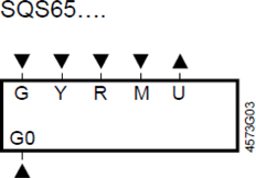
| G, G0 | working voltage AC24 V |
G System Power line (SP), equivalent to LS on SQS56.2 | |
G0 System null line (SN), equivalent to NS on SQS56.2 |
Input Signal
| Y | SQS65, SQS65.5 | DC 0…10 V |
| SQS65.2 | DC 2…10 V | |
| R | SQS65, SQS65.2, SQS65.50…1000 ohms | |
| M | Detecting element | |
| U Output Signal | ||
| SQS65, SQS65.2, SQS65.5 | DC 0…10 V | |
| Siemens Building Technologies | |
| HVAC Products | CM1N4573C/03.2003 |
All connection options are shown on connection diagram. Among these options, how many options and which option used depend on system situation.
Notes: If facility connects onto Terminal R, factory-setting electric bridge through R-M on print circuit board must be punctured.
SQS65, SQS65.5
(AC24 V, DC 0…10 V)

SQS65.2
(AC24 V, Dc 2…10 V)

Facility
| F1 | frost detector | K1 On/off Switch |
| K1 | On/off Switch | N1 typical controller |
| N1 | typical controller | P1 position indictor |
| P1 | position indictor | R1 position converter |
| R1 | position converter | Y1 Actuator |
| Siemens Building Technologies | |
| HVAC Products | CM1N4573C/03.2003 |
Measurement Unit of measurement: mm

* Height after actuator installs on the valve
 > 100mm minimum distance from wall to cover
 >200mm used for places of installation, connection, operation or maintenance
| Siemens Building Technologies | |
| HVAC Products | CM1N4573C/03.2003 |