Exhibit 4.8.4 - Electronic Catalogue (1,3,4,5) - 39CBF39CBFI
Carrier China
Carrier is affiliated to United Technologies. United Technologies ranks 126 in world’s 500 tops (2006), its business extends to architectural industry and aerospace industry around the world.
In 1902, Professor Carrier invented first set of scientific air-conditioning system. Since then, carrier’s complete series products and system resolution have become first choice of many world-renowned buildings.
In 2007, carrier’s sales revenue reaches 14.6 billion US dollars, leading in the whole industry. Its distributors’ network covers over 170 countries. Carrier is now world’s biggest HVAC manufacturer.
Carrier China has 11 companies, 40 sales service offices and 2,500 employees.
As the world-class factory, Carrier Yileng has several advanced production lines of units and compressors, covering main units of commercial and residential central air-conditioning systems and air terminal products. The various products can meet diversifying demands from different customers.
Index
| 39CBFI Series Modular Air-Conditioning Unit | |
| Mark Method of Unit Type | 1 |
| Air Amount scope | 1 |
| Characteristics of Unit | 2 |
| Introduction of software | 4 |
| Control Illusion of Unit | 5 |
| Control | 6 |
| Swift Model Selection | 7 |
| Sketch Map of Function Section | 8 |
| Adjustment of air valve | 9 |
| Cold amount and heat amount of unit and pipe coil configuration | 10 |
| Weight of Pipe Coil | 12 |
| Connection dimension of pipe coil installation | 13 |
| Fan section | 16 |
| Humidifier Option | 19 |
| Silencer | 20 |
| Filter | 21 |
| Specification and number of Filter | 22 |
| Filtering grade of purification needed | 23 |
| Electrical heating section | 24 |
| Case Weight | 24 |
| 39CBF Series Modular Air-Conditioning Unit | |
| Mark Method of 39CBF | 25 |
| Air Amount Scope of 39CBF | 25 |
| Characteristics of Unit 39CBF | 26 |
| Swift Model Selection of 39CBF | 28 |
| Other Specification | 29 |
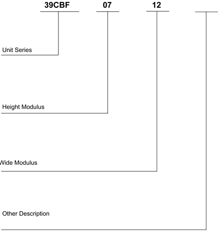
Mark Method of Unit Type
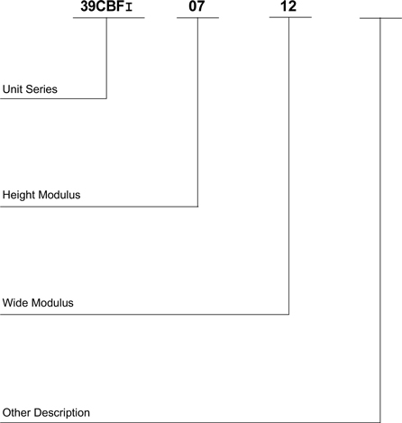
Computing Formula for Unit Modulus and Dimension
39CBFI
(1) Unit Height = Height Modulus × 100 + 100 + 100 (Base)
(2) Unit Width = Width Modulus× 100 + 100
Example:39CBFI 0712
07 Height Modulus
Height of Unit is:7 × 100 + 100 + 100 (底座) =900mm
12 Width Modulus
Width of Unit:12 × 100 + 100 =1300mm
Scope of Air Amount
39CBFI 2209~57766m3/h
1
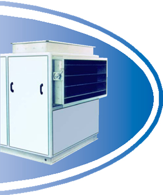
Characteristics of Unit
Double-Panel Structure, Outstanding Heat Prevention
50mm foam panel is light and rigid, and its thermal conductivity is less than 0.0199W/M.℃. The framework and framing strips have been specially treated for insulation, preventing the appearance of cold bridge. Double metal panels are quality color steel sheet and galvanized steel panel, ensuring fire-proof and anti-corrosion performance of the unit. Meanwhile, external panel can be optionally painted by powder of cold-rolled steel sheet, internal panel can be use stainless steel, to satisfy different demand from customers.

New sealing material, minimize air leakage
The case of unit includes panel, framework and gland strip. The panel adopts unique embedding method, so that connection points can be connected precisely. The new gland strip is applied between frame and panel, and each access door and pass-through of pipes has been meticulously designed to ensure air tightness of unit. It completely complies with or beyond the GB/T14294-93.

Elaborate design of water pan
Water pan shall be galvanized steel panel, and stainless steel water pan is available. The down drain method ensures all the condensed water discharged. The lowest point of pipe coil loop equips a freeing port, which can empty the standing water inside pipe coil. This can avoid frost crack of pipe coil.
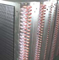
Cold/Hot water pipe coil, international high-level design
| l | Pipe coil employs Carrier’s latest ripple fins to install on copper pipe by mechanic expansion pipe method, which has excellent heat transfer efficiency. Customers can select hydrophilic aluminum foil to more excellent reach heat transfer performance. |
Pipe coil header is steel header, and copper header is available if user has such requirement. The drain valve and air evacuation valve are installed on pipe coil header to ensure no air on loop, meanwhile empty standing water inside pipe coil to avoid frost crack.
| l | When face velocity is more than 2.5m/s, water-dam can be added behind pipe coil, which can effectively separate water from air. |
Corrugated air damper, flexible adjustment
Handle or electric mode can be selected. Using corrugated link mechanism adjustment, and air damper can open flexibly. Electric remote control device can be installed.

2
Unit Base
Each section equips unit base to strength whole machine, reduce unit’s vibration, easy for transport and split joint.

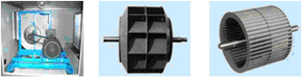
Use optimized “many-swings on front side and curve on back side double intakes centrifugal fan, low noise and high efficiency
Blade wheel and belt pulley have been adjusted by dynamic poise, and whole fan has been regulated by vibration test, so that the whole fan can run smoothly. The base that fan and motor used together installs shock absorbers, soft connection have been provided between air outlet and chassis, so that operational components can be completely isolated, so does shock. The blade of front section or back section can be selected in accordance with air pressure and air flow rate.
Provide all kinds of filers to cater different need
| l | Provide all-level filters, ranging from preliminary filter (board-structure, efficiency can reach G4 level), to medium filter (bag-structure, efficiency can reach F8 level), and high efficiency filter (H13). And provide active carbon filter, filter cartridge filter, antistatic filter and other special filters. |

Modulus design and convenient model selection
The width, height and length of unit add in proportion by modulus of 100mm
Each regulation of flow shall have certain type of unit to match
Modulus products save the material to maximum, control production cost
Standard modules products are convenient and quick for mode shaping and manufacture.

Easy and Convenient Repair
Parts have strong commonality, very easy to change, and price is cheap. Detachable panel can be installed on one side of unit; furthermore, access doors are set to necessary function setting. It is convenient to maintain fan, pipe coil and filters. Pipe coil is installed on lead rail of water pan, easy to maintain, clean and dismantle.

3
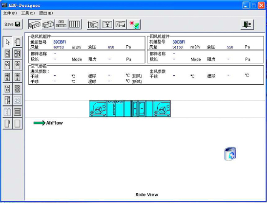
Introduction of Software
Computer Model Selection
The company provides swift and précised computer model selection service. Calculate the most idea function configuration and most economic type.
Function Charateristics
· Project Management
· Modulus Management
· Flexible Combination of Functions
· Provide several configurations according to user’s requirement
· Sub-Box Section Configuration
· Unit Performance Calculation
· Whole-set Quotation
· Output Drawing and technical specification
· Chinese Interface, Easy use
4
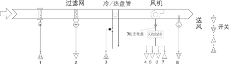
Example of Unit Control
| Control of AC Unit | |||
| Monitor Equipment | Monitor Contents | ||
| AC Unit | Fan Start stop control; Fan Operation Status, Fault Alarm, Handle and auto status; , Filter silting Alarm; (pipe coil freeze protection Alarm) Cold Water Valve regulation, Hot Water Valve Regulation; Fresh-air Damper Adjustment; recirculation door Adjustment; Himidifier Switch; Supply Temperature; Supply Temperature; recirculation humidity level; indoor temperature and humidity level; outdoor temperature and humidity level | ||
Schematic diagram of AC unit (Example) | |||

1 humility of return air | 2 Temperature of Return air | 3 Damper adjustment of Return air | 4 Fresh-air damper adjust | 5 Screen silting Alarm |
6 Hot Water Valve Adjust | 7 Cold Water Valve adjustment | 8 humidifier Switch | 9 Fan Operation Status | 10 Fan Handle or auto Status |
11 Fan Fault | 12 Fan Stop Control | 13 Temperature of Supply Air |
| AC Unit Fresh-Air Control | |||
| Monitor equipment | monitor content | ||
| Fresh-air Unit | Fan Start Stop Control; Fan Operational Status, Fault Alarm, Handle and auto status, filter silt alarm; (pipe coil freeze protection Alarm) Cold Water Valve Adjustment, hot water Valve Adjustment, Fresh-air damper adjustment; temperature of supply air, indoor temperature and humidity, outdoor temperature and humidity | ||
Schematic diagram of Fresh-air unit (Example) | |||
1 Fresh-air Damper openness | 2 Screen Silting Alarm | 3 Valve Adjustment | 4 Fan Operation | 5 handle – Auto Status |
6 Fan Fault Alarm | 7 Fan Start-stop | 8 temperature of Supply air | 9 Outdoor Temperature |
5
Control
Realize single machine and network control to AC unit according to customer’s requirement
Function
| ● | aim to all kinds of AC unit and terminals, provide all-level control system solution |
| ● | Through communication signal line, assemble temperature, humility, valve and damper’s signals on AC unit and terminals, send alarms through internal logical procedure, control valve, damper openness, monitor fan, screen status, auto alarm. |
| ● | Equip special system monitor interface, realizing system control of simple AC Unit. |
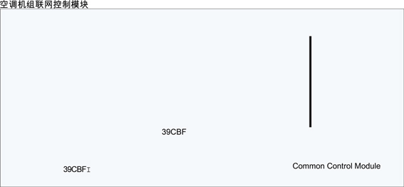
Single Machine Control Module of AC Unit

6
Quick Model Selection
| Unit Specification | Pipe coil in the wind | Outline Diamension | Air | Full Pressure of | |||||||||
| Flow | External unit | ||||||||||||
| 39CFI | Area (m2) | Height H* | Width W | ||||||||||
| 0609 | 0.24 | 700 | 1000 | 2008 | 2209 | 2430 | 200~800 | ||||||
| 0610 | 0.34 | 700 | 1100 | 2755 | 3058 | 3364 | 200~800 | ||||||
| 0712 | 0.49 | 800 | 1300 | 3979 | 4417 | 4859 | 200~800 | ||||||
| 0813 | 0.70 | 900 | 1400 | 5663 | 6286 | 6915 | 200~800 | ||||||
| 0914 | 0.81 | 1000 | 1500 | 6582 | 7306 | 8037 | 200~800 | ||||||
| 1015 | 1.05 | 1100 | 1600 | 8495 | 9429 | 10372 | 200~800 | ||||||
| 1016 | 1.15 | 1100 | 1700 | 9337 | 10364 | 11400 | 200~800 | ||||||
| 1117 | 1.44 | 1200 | 1800 | 11632 | 12912 | 14703 | 200~800 | ||||||
| 1317 | 1.68 | 1400 | 1800 | 13623 | 15121 | 16633 | 200~800 | ||||||
| 1518 | 2.07 | 1600 | 1900 | 16837 | 18689 | 20558 | 200~800 | ||||||
| 1522 | 2.36 | 1600 | 2300 | 19133 | 21238 | 23362 | 200~800 | ||||||
| 1622 | 2.55 | 1700 | 2300 | 20664 | 22937 | 25231 | 200~800 | ||||||
| 1822 | 2.93 | 1900 | 2300 | 23725 | 26335 | 28968 | 200~800 | ||||||
| 1824 | 3.30 | 1900 | 2500 | 26786 | 29733 | 32706 | 200~800 | ||||||
| 1825 | 3.59 | 1900 | 2600 | 29082 | 32281 | 35509 | 200~800 | ||||||
| 2025 | 3.96 | 2100 | 2600 | 30143 | 35679 | 39247 | 200~800 | ||||||
| 2226 | 4.63 | 2300 | 2700 | 37501 | 41626 | 45789 | 200~800 | ||||||
| 2330 | 5.48 | 2400 | 3100 | 44388 | 49271 | 54198 | 200~800 | ||||||
| Unit height, not inclusive of base, 100mm | 400 | 3500 | 52041 | 57766 | 63543 | ||||||||
7
Function Section Sketch
| Serial No. | Description | Simple Graph | Note | |||||
| 1 | Combined Section |  | (0609~0813) 5M 0914~1317) 6M (1518~1622) 8M (1822~2025) 9M (2226~2334) 11M | |||||
| 2 | Bag Filter Section |  | 6M | The function section is recommended to set repair section | ||||
| 3 | Comprehensive Filter Section |  | 6M | The function section is recommended to set repair section | ||||
| 4 | Surface Cold Section |  | 6M | Include water-dam | ||||
| 5 | Hot Water pipe coil section |  | 3M | When surface cold section did not include wet film humidifier and water-dam, can be installed with cold water pan | ||||
| 6 | Steam pipe coil section |  | 3M | |||||
| 7 | Electricity Heat Section |  | 3M | |||||
| 8 | Steam Humidifier Section |  | 6M | |||||
| 9 | Wet Film Humidifying Section |  | 3M | Can directly install with pipe coil, water pan, no space Demand | ||||
| 10 | High Pressure Spray humidifying Section |  | 6M | Can be neighbor with surface cold machine, use water-dam | ||||
| 11 | Fan Section |  | Fan has four air-out directions | |||||
| 12 | Fresh-air return air section |  | (0609~0813) 10M (0914~1825) 12M (2025~2334) 18M | |||||
| 13 | Silencing Section |  | 6M, 12M | The function section is recommended to set repair section | ||||
| 14 | Air Outlet Section |  | (0609~0813) 5M (0914~1317) 6M (1518~1622) 8M (1822~2025) 9M (2226~2334) 11M | The outlet can be on the side or on the top | ||||
| 15 | Empty Section |  | 3M, 6M | |||||
| 16 | High Efficient filter section |  | 9M |
注:以上模数长度仅限于 0609~2334 机组。
8
Sketch Map Identification of Unit Direction
| Direction of unit: | favorable current direction, pipe coil in/out water pipe those the access door on the left are left side door, and verse vise. |

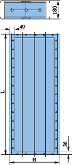
Adjustment Air Valve
It combines return air valve side rod drive openness ripple valve, which is light and flexible to operate, air resistance small, good sealant. It can be hand control, or electronic executor control. The dimension of adjustable air valve shows as follows:
39CBFI | ||
| Unit Spec | L × H | Weight |
39CBFI | mm | kg |
| 0609 | 848.0 × 420.5 | 19.7 |
| 0610 | 948.0 × 420.5 | 20.9 |
| 0712 | 1148.0 × 420.5 | 23.8 |
| 0813 | 1248.0 × 420.5 | 25.3 |
| 0914 | 1348.0 × 578.0 | 36.7 |
| 1015 | 1448.0 × 578.0 | 38.5 |
| 1016 | 1548.0 × 578.0 | 40.0 |
| 1117 | 1648.0 × 578.0 | 42.7 |
| 1317 | 1648.0 × 578.0 | 42.7 |
| 1518 | 1748.0 × 735.0 | 46.0 |
| 1522 | 2148.0 × 735.5 | 62.4 |
| 1622 | 2148.0 × 735.5 | 62.4 |
| 1822 | 2148.0 × 893.0 | 72.0 |
| 1824 | 2348.0 × 893.0 | 76.8 |
| 1825 | 2448.0 × 893.0 | 79.5 |
| 2025 | 2448.0 × 893.0 | 79.5 |
| 2226 | 2548.0 × 1050.5 | 89.7 |
| 2330 | 2948.0 × 1050.5 | 100.7 |
| 2334 | 3348.0 × 1050.5 | 111.0 |
9
Cold Amount and heat amount of unit, and configuration of pipe coil
Unit equipped with cold/hot water pipe coil and heat pipe coil. The cold/hot water pipe coil can use cold water and hot water in winter and summer in turn. Heat pipe coil is heated by special hot water, or select steam pipe coil.
4 Row | 6 Row | |||||||||
Unit Spec | air volume | Total cold | A. cold | Air .resist. | Water Flow | Water Resis | Loop | Total C | A. cold | Air Resist |
39CBFI | (CMH) | (kW) | (kW) | (Pa) | (L/s) | (kPa) | (kW) | (kW) | (Pa) | |
| 0609 | 2209 | 12.1 | 9.12 | 128 | 0.58 | 7.9 | HF | 17.16 | 11.75 | 196 |
| 0610 | 3058 | 16.58 | 11.90 | 124 | 0.79 | 12.4 | HF | 24.69 | 16.65 | 188 |
| 0712 | 4417 | 23.92 | 17.11 | 126 | 1.1 | 17.1 | HF | 36.07 | 24.24 | 192 |
| 0813 | 6286 | 35.39 | 25.27 | 126 | 1.7 | 34.6 | HF | 48.28 | 33.18 | 191 |
| 0914 | 7306 | 40.83 | 29.04 | 128 | 1.96 | 39.5 | HF | 55.62 | 38.37 | 192 |
| 1015 | 9429 | 53.41 | 38.08 | 127 | 2.6 | 46.9 | HF | 72.84 | 49.96 | 191 |
| 1016 | 10364 | 59.51 | 42.16 | 128 | 2.85 | 55.8 | HF | 81.18 | 55.39 | 191 |
| 1117 | 12912 | 79.53 | 58.65 | 125 | 3.8 | 17.8 | FL | 103.39 | 69.97 | 191 |
| 1317 | 15121 | 93.44 | 68.79 | 126 | 4.5 | 20.8 | FL | 121.26 | 82.01 | 192 |
| 1518 | 18689 | 116.43 | 85.41 | 127 | 5.6 | 26.7 | FL | 150.61 | 101.68 | 193 |
| 1522 | 21238 | 135.61 | 98.38 | 127 | 6.5 | 25.2 | FL | 173.71 | 116.64 | 192 |
| 1622 | 22937 | 145.83 | 105.99 | 127 | 7 | 27.7 | FL | 187.1 | 125.76 | 192 |
| 1822 | 26335 | 167.58 | 121.76 | 127 | 8 | 28.1 | FL | 214.93 | 144.44 | 192 |
| 1824 | 29733 | 193.22 | 139.09 | 128 | 9.2 | 35.6 | FL | 245.77 | 164.41 | 193 |
| 1825 | 32281 | 212.52 | 152.13 | 128 | 10.2 | 45 | FL | 257.06 | 174.31 | 191 |
| 2025 | 35679 | 234.3 | 167.90 | 128 | 11.2 | 44.8 | FL | 283.45 | 192.37 | 191 |
| 2226 | 41628 | 275.39 | 196.72 | 129 | 13.2 | 51.8 | FL | 332.93 | 225.39 | 191 |
| 2330 | 49271 | 331.15 | 234.96 | 129 | 15.8 | 69.5 | FL | 399.05 | 268.91 | 192 |
| 2334 | 57766 | *371.14 | *268.51 | *129 | *14.1 | *68.9 | FL | *450.89 | *308.05 | *193 |
Standard operation
6 Row | 8 row | |||||||||
| Air | ||||||||||
Unit Spec | volume | W Flow | Water Resis | Loop | Total Cold | A. Cold | Air Resistant | Water Fl | Water Resis | Loop |
| 39CBFI | (CMH) | (L/s) | (kPa) | (kW) | (kW) | (Pa) | (L/s) | (kPa) | ||
| 0609 | 2209 | 0.8 | 16.1 | HF | 19.7 | 12.91 | 264 | 0.9 | 26.6 | HF |
| 0610 | 3058 | 1.2 | 40.2 | HF | 27.73 | 18.07 | 253 | 1.3 | 64.2 | HF |
| 0712 | 4417 | 1.7 | 43.58 | HF | 37.96 | 25.18 | 254 | 1.8 | 14.8 | FL |
| 0813 | 6286 | 2.3 | 19.1 | FL | 55.05 | 36.28 | 257 | 2.6 | 29.2 | FL |
| 0914 | 7306 | 2.7 | 19.6 | FL | 63.8 | 42.09 | 258 | 3.1 | 29.5 | FL |
| 1015 | 9429 | 3.5 | 18.6 | FL | 83.77 | 54.95 | 256 | 4 | 29.5 | FL |
| 1016 | 10364 | 3.9 | 24.1 | FL | 92.6 | 60.76 | 257 | 4.4 | 38 | FL |
| 1117 | 12912 | 4.9 | 37.7 | FL | 116.72 | 76.14 | 256 | 5.6 | 57.8 | FL |
| 1317 | 15121 | 5.8 | 43.1 | FL | 136.75 | 89.19 | 257 | 6.5 | 64.6 | FL |
| 1518 | 18689 | 7.2 | 41.8 | FL | 169.37 | 110.39 | 259 | 8.1 | 65.2 | FL |
| 1522 | 21238 | 8.3 | 54.1 | FL | 182.96 | 121.25 | 256 | 8.7 | 22.6 | DB |
| 1622 | 22937 | 8.9 | 58.1 | FL | 196.83 | 130.62 | 256 | 9.4 | 23.8 | DB |
| 1822 | 26335 | 10.3 | 59.5 | FL | 226.3 | 150.1 | 256 | 10.8 | 18.8 | DB |
| 1824 | 29733 | 11.8 | 75.8 | FL | 258.44 | 170.76 | 257 | 12.4 | 25.8 | DB |
| 1825 | 32281 | 12.3 | 36.6 | DB | 282.03 | 186.02 | 258 | 13.5 | 31.4 | DB |
| 2025 | 35679 | 13.6 | 37.8 | DB | 311.39 | 205.46 | 258 | 14.9 | 33.5 | DB |
| 2226 | 41628 | 15.9 | 43.7 | DB | 364.32 | 240.16 | 258 | 17.4 | 38.5 | DB |
| 2330 | 49271 | 19.1 | 57.7 | DB | 433.94 | 285.45 | 259 | 20.8 | 49.8 | DB |
| 2334 | 57766 | 18 | 56.8 | DB | 521.38 | 340.26 | 259 | 24.9 | 76.1 | DB |
HF—Semi loop FL—Full Loop DB—Double Loop Standard Operation Condition:inlet dry bulb temperature —27ºC inlet wet bulb temperature —19.5ºC inlet water —7ºC Note:* refers to control refrigerating water pipe pressure drop , differential return water temperature is 5ºC
10
Cold Amount and heat amount of unit, and configuration of pipe coil
| Unit Cold | |
| Amount | Fresh-air |
| Operational | |
| Condition |
| Unit spec | Air volume | 4 Row | 6 Row | |||||||
| 39CBFI | (CMH) | Total Cold | A. Cold | Air Resist | Water Res | Water Flow | Loop | T Cold | A Cold | Air Consist |
| (kW) | (kW) | (Pa) | (L/s) | (kPa) | (kW) | (kW) | (Pa) | |||
| 0609 | 2209 | 31.55 | 13.66 | 134 | 1.5 | 27 | HF | 39.51 | 16.75 | 201 |
| 0610 | 3058 | 45.81 | 19.63 | 128 | 2.2 | 59.4 | HF | 51.03 | 21.75 | 193 |
| 0712 | 4417 | 59.83 | 26.18 | 130 | 2.9 | 15.1 | FL | 76.05 | 32.32 | 195 |
| 0813 | 6286 | 87.31 | 38.01 | 131 | 4.2 | 28 | FL | 109.86 | 46.64 | 197 |
| 0914 | 7306 | 102.48 | 44.53 | 132 | 4.9 | 49.2 | FL | 128.37 | 54.48 | 198 |
| 1015 | 9429 | 133.99 | 58.08 | 130 | 6.4 | 52.5 | FL | 160.2 | 68.89 | 195 |
| 1016 | 10364 | *149.59 | 64.66 | 131 | 7.2 | 59.0 | FL | 177.02 | 76.12 | 196 |
| 1117 | 12912 | *183.57 | *79.32 | *131 | *7.3 | *60.1 | FL | *214.73 | *92.33 | *196 |
| 1317 | 15121 | *215.15 | *92.94 | *132 | *8.6 | *70.3 | FL | *253.28 | 108.91 | *197 |
| 1518 | 18689 | *261.47 | *113.29 | *132 | *9.6 | *62 | FL | *314.54 | *135.25 | *197 |
| 1522 | 21238 | *296.3 | *128.45 | *131 | *10.1 | *63.6 | FL | *348.73 | *149.95 | *196 |
| 1622 | 22937 | *318.64 | *138.24 | *132 | *10.9 | *62.9 | FL | *379.61 | *163.23 | *196 |
| 1822 | 26335 | *366.3 | *158.88 | *132 | *12.5 | *65.3 | FL | *435.05 | *187.07 | *196 |
| 1824 | 29733 | *412.33 | *178.94 | *133 | *13.1 | *57.4 | FL | *490.59 | *210.96 | *197 |
| 1825 | 32281 | *443.04 | *192.65 | *133 | *313.2 | *61.6 | FL | *531.97 | *226.88 | *197 |
| 2025 | 35679 | *488.74 | *212.6 | *133 | *14.6 | *68 | FL | *585.95 | *250 | *197 |
| 2226 | 41628 | *561.78 | *245.1 | *134 | *15.8 | *69.8 | FL | *675.37 | *288.55 | *198 |
| 2330 | 49271 | *795.42 | *340.05 | *198 | ||||||
| 2334 | 57766 | *916.95 | *392.85 | *198 | ||||||
Fresh-air operation condition
6 Row | 8 Row | |||||||||
| Unit Spec | Air | |||||||||
| 39CBFI | Volume | W Flow | Flow Resist | Loop | T. Cold | A. Cold | Air Resis | W Flow | Water Resi | Loop |
| (CMH) | (L/s) | (kPa) | (kW) | (kW) | (Pa) | (L/s) | (kPa) | |||
| 0609 | 2209 | 1.9 | 63 | HF | 41.12 | 17.41 | 268 | 2 | 12.7 | FL |
| 0610 | 3058 | 2.4 | 18.8 | FL | 57.83 | 24.48 | 257 | 2.8 | 20.6 | FL |
| 0712 | 4417 | 3.6 | 31.6 | FL | 85.25 | 36.09 | 260 | 4.1 | 40.3 | FL |
| 0813 | 6286 | 5.3 | 52.6 | FL | 119.37 | 50.14 | 267 | 5.7 | 28.47 | DB |
| 0914 | 7306 | 6.1 | 64.9 | FL | 138.16 | 58.03 | 268 | 6.6 | 31.08 | DB |
| 1015 | 9429 | 7.7 | 36.15 | DB | 177.27 | 75.45 | 266 | 8.5 | 34.2 | DB |
| 1016 | 10364 | 8.5 | 38.88 | DB | 192.67 | 80.92 | 267 | 9.2 | 34.88 | DB |
| 1117 | 12912 | *8.5 | *40.12 | DB | *241.20 | *101.30 | *266 | *9.6 | *37.91 | DB |
| 1317 | 15121 | *10.1 | *38.93 | DB | *283.07 | *118.89 | *267 | *11.3 | *38.25 | DB |
| 1518 | 18689 | *11.6 | *41.76 | DB | *349.11 | *146.63 | *269 | *12.8 | *38.88 | DB |
| 1522 | 21238 | *11.9 | *51.7 | DB | *389.59 | *165.04 | *268 | *13.3 | *41.3 | DB |
| 1622 | 22937 | *13 | *53.9 | DB | *418.82 | *177.46 | *267 | *14.3 | *50 | DB |
| 1822 | 26335 | *14.8 | *52.36 | DB | *481.33 | *203.93 | *267 | *16.4 | *52.8 | DB |
| 1824 | 29733 | *15.6 | *57.6 | DB | *542.69 | *229.64 | *268 | *17.3 | *48 | DB |
| 1825 | 32281 | *15.9 | *58.7 | DB | *584.99 | *247.94 | *268 | *17.5 | *50.9 | DB |
| 2025 | 35679 | *17.5 | *60.6 | DB | *645.87 | *273.76 | *269 | *19.3 | *54.5 | DB |
| 2226 | 41628 | *19 | *60.4 | DB | *745.61 | *316.21 | *269 | *21 | *54.5 | DB |
| 2330 | 49271 | *21.9 | *69.2 | DB | *879.19 | *372.94 | *269 | *23.4 | *61.9 | DB |
| 2334 | 57766 | *21.9 | *76.7 | DB | *1016.91 | *431.73 | *269 | *24.3 | *72 | DB |
HF—Semi loop FL—Full Loop DB—Double Loop Standard Operation Condition:inlet dry bulb temperature —35ºC inlet wet bulb temperature —28ºC inlet water —7ºC Note:* refers to control refrigerating water pipe pressure drop , differential return water temperature is 5ºC
11
Cold Amount and heat amount of unit, and configuration of pipe coil
Unit Heat Energy:(2 Row)
| Inlet temperature of hot water | ||||||||||||
| Unit Spec | 60 °C | 70 °C | 80°C | |||||||||
| 39CBFI | Heat | air resist | w resist | w Flow | Heat | air resist | w resist | w Flow | Heat | air resist | w resist | w Flow |
| (kW) | (Pa) | (kPa) | (L/s) | (kW) | (Pa) | (kPa) | (L/s) | (kW) | (Pa) | (kPa) | (L/s) | |
| 0609 | 12.79 | 55 | 1.0 | 0.3 | 20.22 | 56 | 2.2 | 0.5 | 22.92 | 57 | 2.8 | 0.5 |
| 0610 | 20.42 | 56 | 2.8 | 0.5 | 78.58 | 60 | 4.8 | 0.7 | 32.38 | 54 | 6.4 | 0.8 |
| 0712 | 32.34 | 58 | 4.2 | 0.8 | 41.72 | 58 | 6.6 | 1.0 | 47.19 | 55 | 8.6 | 1.1 |
| 0813 | 43.34 | 54 | 7.0 | 1.0 | 60.47 | 57 | 8.7 | 1.3 | 72.16 | 62 | 10.1 | 1.4 |
| 0914 | 54.38 | 61 | 7.5 | 1.2 | 69.91 | 58 | 11.8 | 1.6 | 83.63 | 62 | 12.8 | 1.7 |
| 1015 | 70.73 | 60 | 10.4 | 1.6 | 90.73 | 61 | 16.4 | 2.1 | 108.46 | 61 | 17.7 | 2.2 |
| 1016 | 78.40 | 55 | 13.2 | 1.8 | 92.25 | 60 | 17.8 | 2.1 | 119.29 | 61 | 18.8 | 2.2 |
| 1117 | 91.03 | 55 | 17.4 | 2.1 | 115.38 | 56 | 24.1 | 2.5 | 137.06 | 55 | 24.6 | 2.5 |
| 1317 | 114.81 | 61 | 21.3 | 2.5 | 134.37 | 55 | 26.9 | 2.8 | 160.37 | 55 | 28.7 | 3.0 |
| 1518 | 141.54 | 62 | 25.5 | 3.0 | 166.57 | 62 | 34.5 | 3.5 | 198.72 | 56 | 36.9 | 3.7 |
| 1522 | 151.63 | 58 | 16.0 | 3.2 | 196.27 | 59 | 26.0 | 4.1 | 235.90 | 61 | 29.5 | 4.3 |
| 1622 | 162.63 | 58 | 17.4 | 3.4 | 211.41 | 59 | 29.2 | 4.4 | 258.37 | 61 | 36.4 | 5.2 |
| 1822 | 186.85 | 55 | 22.1 | 3.9 | 242.87 | 60 | 37.3 | 5.1 | 291.96 | 61 | 42.4 | 5.4 |
| 1824 | 214.15 | 59 | 29.2 | 4.5 | 276.48 | 58 | 47.2 | 5.7 | 333.27 | 55 | 50.9 | 6.1 |
| 1825 | 233.49 | 61 | 33.7 | 4.8 | 302.41 | 60 | 56.8 | 6.2 | 363.08 | 61 | 64.7 | 6.6 |
| 2025 | 257.75 | 57 | 40.1 | 5.3 | 333.67 | 58 | 67.4 | 6.8 | 398.91 | 61 | 70.7 | 7.1 |
| 2226 | 320.56 | 58 | 55.7 | 6.6 | 374.32 | 57 | 70.5 | 7.5 | 445.08 | 55 | 72.8 | 7.6 |
| 2330 | 348.95 | 60 | 58.4 | 7.0 | 461.95 | 60 | 71.1 | 9.0 | 530.27 | 55 | 75.8 | 11.5 |
| 2334 | 446.20 | 58 | 66.2 | 9.7 | 553.49 | 58 | 74.4 | 11.3 | 660.44 | 61 | 79.8 | 11.7 |
Note: Inlet dry bulb temperature —15ºC; from 0609 to 1518 unit employs semi-loop, from 1522 to 2334 unit employs full loop。
Weight of pipe coil section
(单位: kg)
| Unit Number | Pipe Coil Number | |||
| 39CBFI | 2 Row | 4 Row | 6 Row | 8 Row |
| 0609 | 35.30 | 73.16 | 77.70 | 83.92 |
| 0610 | 40.30 | 78.42 | 84.62 | 92.77 |
| 0712 | 42.60 | 89.86 | 98.80 | 104.68 |
| 0813 | 47.36 | 97.27 | 108.26 | 122.00 |
| 0914 | 51.30 | 103.46 | 115.90 | 131.38 |
| 1015 | 54.00 | 114.76 | 131.21 | 151.08 |
| 1016 | 56.36 | 119.38 | 137.55 | 159.12 |
| 1117 | 64.01 | 131.26 | 153.89 | 180.26 |
| 1317 | 69.90 | 142.88 | 169.35 | 187.94 |
| 1518 | 75.53 | 160.33 | 193.00 | 230.45 |
| 1522 | 111.54 | 178.95 | 217.85 | 256.74 |
| 1622 | 116.32 | 187.78 | 228.89 | 271.11 |
| 1822 | 124.14 | 204.02 | 252.26 | 300.51 |
| 1824 | 128.02 | 226.15 | 273.16 | 327.49 |
| 1825 | 129.86 | 228.14 | 288.05 | 347.01 |
| 2025 | 136.98 | 254.93 | 319.51 | 384.74 |
| 2226 | 166.16 | 284.69 | 359.83 | 435.83 |
| 2330 | 188.06 | 323.33 | 412.93 | 504.93 |
| 2334 | 206.11 | 363.44 | 468.24 | 576.24 |
Note:The weight on the chart only refers to the weight of pipe coil, exclusive of weight of box.
12
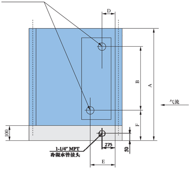
Connection dimension of installation of pipe coil
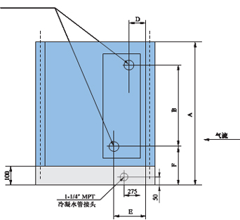
* MPT- outside thread
| 39CBFI | A | B | øC | F |
| 0609 | 800 | 357 | 1— ″ | 233 |
| 1/2 MPT | ||||
| 0610 | 800 | 421 | 1— ″ | 233 |
| 1/2 MPT | ||||
| 0712 | 900 | 484 | 1— ″ | 233 |
| 1/2 MPT | ||||
| 0813 | 1000 | 611 | 1— ″ | 233 |
| 0914 | 1100 | 675 | 1/2 MPT | 233 |
| 1015 | 1200 | 802 | 1— ″ | 233 |
| 1/2 MPT | ||||
| 1016 | 1200 | 802 | 1— ″ | 233 |
| 1/2 MPT | ||||
| 1117 | 1300 | 917 | 1— ″ | 240 |
| 1/2 MPT | ||||
| 1317 | 1500 | 1107 | 1— ″ | 240 |
| 1/2 MPT | ||||
| 1518 | 1700 | 1298 | 240 |
| 39CBFI | D | E | øC |
2 排 热水 | 55 | 138 | 1-1/2″ |
4 排 | 91 | 173 | |
6 排 | 63 | 201 | 见上表 |
8 排 | 88 | 226 |
| 39CBFI | A | B | øC | F |
| 1522 | 1700 | 1298 | 2″ MPT | 240 |
| 1622 | 1800 | 1361 | 2″ MPT | 240 |
| 1822 | 2000 | 1523 | 3″ MPT | 254 |
| 1824 | 2000 | 1523 | 3″ MPT | 254 |
| 1825 | 2000 | 1523 | 3″ MPT | 254 |
| 39CBFI | D | E | øC |
2 row hot water | 55 | 138 | 1-1/2″ |
4 row(diameter 2″ MPT) | 116 | 198 | Refer to |
4 row(diameter 3″ MPT) | 88 | 226 | above chart |
6 row、8 row | 88 | 226 |
13
Connection dimension of installation of pipe coil

| 39CBFI | A | B | øC | øF |
| 2025 | 2200 | 982 | 2″ MPT | 3″ MPT |
| 2226 | 2400 | 1173 | 2″ MPT | 3″ MPT |
| 2330 | 2500 | 1300 | 2″ MPT | 3″ MPT |
| 2334 | 2500 | 1300 | 2″ MPT | 3″ MPT |
| 39CBFI | D1 | D2 | E1 | E2 | øC |
2 row hot | 55 | 138 | 1-1/2” MPT | ||
4 row | 116 | 88 | 198 | 226 | Refer to above |
6 row 8 Row | 88 | 226 | chart avove | ||
Steam pipe coil Section
(Unit: kW)
| Unit Spec | Pipe Coil | Steam | Weight | ||
| 39CBFI | Type | Pressure(MPa) | kg | ||
| 0609 | (GL-2R-09-06)× 1 | 28.3 | 32.6 | 36.2 | 45 |
| 0610 | (GL-2R-09-07)× 1 | 38.2 | 44.2 | 49.1 | 48 |
| 0712 | (GL-2R-11-09)× 1 | 53.9 | 62.3 | 69.1 | 57 |
| 0813 | (GL-2R-15-10)× 1 | 76.4 | 88.3 | 97.9 | 80 |
| 0914 | (GL-2R-17-11)× 1 | 92.1 | 106.5 | 118.1 | 98 |
| 1015 | (GL-2R-19-12)× 1 | 115.9 | 136.7 | 151.5 | 107 |
| 1016 | (GL-2R-19-13)× 1 | 129.6 | 149.9 | 166.2 | 114 |
| 1117 | (GL-2R-22-14)× 1 | 161.1 | 186.4 | 206.7 | 126 |
| 1317 | (GL-2R-13-14)× 2 | 188.5 | 217.9 | 241.6 | 167 |
| 1518 | (GL-2R-15-15)× 2 | 234.9 | 271.6 | 301.3 | 212 |
| 1522 | (GL-2R-15-19)× 2 | 271.4 | 313.8 | 348.1 | 243 |
| 1622 | (GL-2R-17-19)× 2 | 298.9 | 345.7 | 382.8 | 269 |
| 1822 | (GL-2R-19-19)× 2 | 345.6 | 399.4 | 442.7 | 286 |
| 1824 | (GL-2R-19-21)× 2 | 387.4 | 448.1 | 496.3 | 303 |
| 1825 | (GL-2R-19-22)× 2 | 416.6 | 481.7 | 533.0 | 320 |
| 2025 | (GL-2R-22-22)× 2 | 464.8 | 537.8 | 595.5 | 354 |
| 2226 | (GL-2R-22-23)× 2 | 525.6 | 607.3 | 672.5 | 374 |
| 2330 | (GL-2R-22-27)× 2 | 620.7 | 717.4 | 795.9 | 413 |
| 2334 | (GL-2R-22-31)× 2 | 724.0 | 835.8 | 927.9 | 471 |
注: Inlet Day-bulb temperature is 7ºC .the weight on the chart only refers to the weight of pipe coil, exclusive of weight of box. |
14

| 39CBFI | A | B | øC | F |
| 0609 | 800 | 287 | 2″ MPT | 278 |
| 0610 | 800 | 287 | 2″ MPT | 278 |
| 0712 | 900 | 358 | 2″ MPT | 278 |
| 0813 | 1000 | 500 | 2″ MPT | 278 |
| 0914 | 1100 | 571 | 2″ MPT | 278 |
| 1015 | 1200 | 678 | 2″ MPT | 278 |
| 1016 | 1200 | 678 | 2″ MPT | 278 |
| 1117 | 1300 | 784 | 2″ MPT | 278 |
| 39CBFI | D | E |
2 排 | 80 | 154 |

| 39CBFI | A | B | øC | F |
| 1317 | 1500 | 429 | 2″ MPT | 278 |
| 1518 | 1700 | 500 | 2″ MPT | 278 |
| 1522 | 1700 | 500 | 2″ MPT | 278 |
| 1622 | 1800 | 571 | 2″ MPT | 278 |
| 1822 | 2000 | 678 | 2″ MPT | 278 |
| 1824 | 2000 | 678 | 2″ MPT | 278 |
| 1825 | 2000 | 678 | 2″ MPT | 278 |
| 2025 | 2200 | 784 | 2″ MPT | 278 |
| 2226 | 2400 | 784 | 2″ MPT | 478 |
| 2330 | 2500 | 784 | 2″ MPT | 478 |
| 2334 | 2500 | 784 | 2″ MPT | 478 |
| 39CBFI | D | E |
2 排 | 80 | 154 |
15
Fan Section
Configuration of fan and motor
Unit Spec 39CBFI | Fitting Fan | Max Power of Fan (kW) | Max seat of Fan | Length of Fan Section(mm) HorizontaVertical | Weight(kg) | |
| 0609 | ADZ180 | 1.5 | Y90 | 600 | 900 | 20.55 |
| 0610 | ADZ180 | 2.2 | Y100 | 600 | 900 | 20.55 |
| ADZ200 | 700 | 900 | 23.21 | |||
| 0712 | ADZ225 | 3.7 | Y112 | 700 | 900 | 32.98 |
| ADZ/RDZ250 | 700 | 900 | 34.98/37.08 | |||
| 0813 | ADZ/RDZ280 | 5.5 | Y132 | 800 | 900 | 41.44/43.64 |
| ADZ/RDZ315 | 800 | 900 | 46.44/47.64 | |||
| 0914 | ADZ/RDZ315 | 5.5 | Y132 | 800 | 900 | 46.44/47.64 |
| ADZ/RDZ355 | 900 | 900 | 60.41/64.41 | |||
| 1015 | ADZ/RDZ355 | 7.5 | Y132 | 900 | 900 | 60.41/64.41 |
| ADZ/RDZ400 | 900 | 900 | 73.48/76.48 | |||
| 1016 | ADZ/RDZ355 | 7.5 | Y132 | 900 | 900 | 64.21/68.21 |
| ADZ/RDZ400 | 900 | 900 | 77.21/80.21 | |||
| 1117 | ADZ/RDZ400 | 11 | Y160 | 900 | 900 | 79.02/82.02 |
| ADZ/RDZ450 | 1100 | 1100 | 88.02/97.52 | |||
| 1317 | ADZ/RDZ400 | 15 | Y160 | 900 | 900 | 79.02/82.02 |
| ADZ/RDZ450 | 1100 | 1100 | 88.02/97.52 | |||
| 1518 | ADZ/RDZ450 | 15 | Y160 | 1100 | 1100 | 88.02/97.52 |
| ADZ/RDZ500 | 1100 | 1100 | 97.16/108.16 | |||
| 1522 | ADZ/RDZ500 | 18.5 | Y180 | 1100 | 1100 | 97.16/108.16 |
| ADZ/RDZ560 | 1300 | 1300 | 186.0/195.0 | |||
| 1622 | ADZ/RDZ560 | 18.5 | Y180 | 1300 | 1300 | 186.0/195.0 |
| ADZ/RDZ630 | 1400 | 1400 | 250.0/253.0 | |||
| 1822 | ADZ/RDZ560 | 18.5 | Y180 | 1300 | 186.0/195.0 | |
| ADZ/RDZ630 | 1400 | 250.0/253.0 | ||||
| 1824 | ADZ/RDZ560 | 22 | Y180 | 1300 | 186.0/195.0 | |
| ADZ/RDZ630 | 1400 | 250.0/253.0 | ||||
| 1825 | ADZ/RDZ630 | 30 | Y200 | 1400 | 250.0/253.0 | |
| ADZ/RDZ710 | 1500 | 281.0/323.0 | ||||
| 2025 | ADZ/RDZ630 | 30 | Y200 | 1400 | 250.0/253.0 | |
| ADZ/RDZ710 | 1500 | 281.0/323.0 | ||||
| 2226 | ADZ/RDZ710 | 30 | Y200 | 1500 | 281.0/323.0 | |
| ADZ/RDZ800 | 1700 | 370.0/405.0 | ||||
| 2330 | ADZ/RDZ800 | 37 | Y225 | 1700 | 370.0/405.0 | |
| ADZ/RDZ900 | 1900 | 442.0/490.0 | ||||
| 2334 | ADZ/RDZ800 | 45 | Y225 | 1700 | 370.0/405.0 | |
| ADZ/RDZ900 | 1900 | 442.0/490.0 | ||||
Note: The weight on the chart only refers to the weight of pipe coil, exclusive of weight of box.,
16
Fan Section
Outlet direction of horizontal unit and flange size

(单位:mm)
Unit Spec 39CBFI | Fitting Fan | A | D | E | |||
| THF | BHF | UBF | UBR | ||||
| 0609 | ADZ180 | 289.5 | 229 | 290.5 | 193.5 | 125 | 222 |
| 0610 | ADZ180 | 314.5 | 229 | 290.5 | 193.5 | 125 | 222 |
| ADZ200 | 312.5 | 256 | 298.5 | 192.5 | 125 | 231 | |
| 0712 | ADZ/RDZ225 | 411.5 | 288 | 312.5 | 192.5 | 125 | 268 |
| ADZ/RDZ250 | 411.5 | 322 | 324.0 | 192.0 | 125 | 257 | |
| 0813 | ADZ/RDZ280 | 392.5 | 361 | 340.5 | 193.5 | 125 | 306 |
| ADZ/RDZ315 | 349.5 | 404 | 359.5 | 191.5 | 125 | 293 | |
| 0914 | ADZ/RDZ315 | 399.5 | 404 | 359.5 | 191.5 | 125 | 293 |
| ADZ/RDZ355 | 391.5 | 453 | 384.5 | 194.5 | 125 | 315 | |
| 1015 | ADZ/RDZ355 | 441.5 | 453 | 384.5 | 194.5 | 125 | 315 |
| ADZ/RDZ400 | 391.5 | 507 | 413.0 | 193.0 | 125 | 345 | |
| 1016 | ADZ/RDZ355 | 491.5 | 453 | 384.5 | 194.5 | 125 | 315 |
| ADZ/RDZ400 | 491.5 | 507 | 413.0 | 193.0 | 125 | 345 | |
| 1117 | ADZ/RDZ400 | 541.5 | 507 | 413.0 | 193.0 | 125 | 345 |
| ADZ/RDZ450 | 424.5 | 569 | 441.5 | 193.5 | 125 | 373 | |
| 1317 | ADZ/RDZ400 | 541.5 | 507 | 413.0 | 193.0 | 125 | 345 |
| ADZ/RDZ450 | 379.5 | 569 | 441.5 | 193.5 | 125 | 373 | |
| 1518 | ADZ/RDZ450 | 429.5 | 569 | 441.5 | 193.5 | 125 | 373 |
| ADZ/RDZ500 | 410.5 | 638 | 463.5 | 193.5 | 125 | 395 | |
| 1522 | ADZ/RDZ500 | 610.5 | 638 | 463.5 | 193.5 | 125 | 395 |
| ADZ/RDZ560 | 617.5 | 715 | 554.5 | 253.5 | 125 | 426 | |
| 1622 | ADZ/RDZ560 | 617.5 | 715 | 554.5 | 253.5 | 125 | 426 |
| ADZ/RDZ630 | 531.5 | 801 | 596.5 | 252.5 | 125 | 469 | |
| 1822 | ADZ/RDZ560 | 617.5 | 715 | 554.5 | 253.5 | 125 | 426 |
| ADZ/RDZ630 | 531.5 | 801 | 596.5 | 252.5 | 125 | 469 | |
| 1824 | ADZ/RDZ560 | 717.5 | 715 | 554.5 | 253.5 | 125 | 426 |
| ADZ/RDZ630 | 691.5 | 801 | 596.5 | 252.5 | 125 | 469 | |
| 1825 | ADZ/RDZ630 | 741.5 | 801 | 596.5 | 252.5 | 125 | 469 |
| ADZ/RDZ710 | 629.5 | 898 | 644.5 | 253.5 | 125 | 516 | |
| 2025 | ADZ/RDZ630 | 741.5 | 801 | 596.5 | 252.5 | 125 | 469 |
| ADZ/RDZ710 | 629.5 | 898 | 644.5 | 253.5 | 125 | 516 | |
| 2226 | ADZ/RDZ710 | 679.5 | 898 | 644.5 | 253.5 | 125 | 516 |
| ADZ/RDZ800 | 620.0 | 1007 | 713.5 | 266.5 | 125 | 572 | |
| 2330 | ADZ/RDZ800 | 820.0 | 1007 | 713.5 | 266.5 | 125 | 572 |
| ADZ/RDZ900 | 792.0 | 1130 | 770.5 | 266.5 | 125 | 629 | |
| 2334 | ADZ/RDZ800 | 1020.0 | 1007 | 713.5 | 266.5 | 125 | 572 |
| ADZ/RDZ900 | 1167.0 | 1130 | 770.5 | 266.5 | 125 | 629 | |
17
Fan Section
Outlet direction of vertical unit and flange size

(单位:mm)
Unit Spec 39CBFI | Fitting Fan | A | D | E | |||
| THF | BHF | UBF | UBR | ||||
| 0609 | ADZ180 | 289.5 | 229 | 940.5 | 843.5 | 125 | 222 |
| 0610 | ADZ180 | 339.5 | 229 | 940.5 | 843.5 | 125 | 222 |
| ADZ200 | 312.5 | 256 | 948.5 | 842.5 | 125 | 231 | |
| 0712 | ADZ/RDZ225 | 411.5 | 288 | 1062.5 | 842.5 | 125 | 268 |
| ADZ/RDZ250 | 411.5 | 322 | 1074.0 | 942.0 | 125 | 257 | |
| 0813 | ADZ/RDZ280 | 392.5 | 361 | 1190.5 | 1043.5 | 125 | 306 |
| ADZ/RDZ315 | 349.5 | 404 | 1209.5 | 1041.5 | 125 | 293 | |
| 0914 | ADZ/RDZ315 | 399.5 | 404 | 1309.5 | 1141.5 | 125 | 293 |
| ADZ/RDZ355 | 391.5 | 453 | 1334.5 | 1144.5 | 125 | 315 | |
| 1015 | ADZ/RDZ355 | 441.5 | 453 | 1434.5 | 1244.5 | 125 | 315 |
| ADZ/RDZ400 | 391.5 | 507 | 1463.0 | 1243.0 | 125 | 345 | |
| 1016 | ADZ/RDZ355 | 491.5 | 453 | 1434.5 | 1244.5 | 125 | 315 |
| ADZ/RDZ400 | 491.5 | 507 | 1463.0 | 1243.0 | 125 | 345 | |
| 1117 | ADZ/RDZ400 | 541.5 | 507 | 1563.0 | 1343.0 | 125 | 345 |
| ADZ/RDZ450 | 424.5 | 569 | 1591.5 | 1343.5 | 125 | 373 | |
| 1317 | ADZ/RDZ400 | 541.5 | 507 | 1763.0 | 1543.0 | 125 | 345 |
| ADZ/RDZ450 | 379.5 | 569 | 1791.5 | 1543.5 | 125 | 373 | |
| 1518 | ADZ/RDZ450 | 429.5 | 569 | 1991.5 | 1743.5 | 125 | 373 |
| ADZ/RDZ500 | 410.5 | 638 | 2013.5 | 1743.5 | 125 | 395 | |
| 1522 | ADZ/RDZ500 | 610.5 | 638 | 2013.5 | 1743.5 | 125 | 395 |
| ADZ/RDZ560 | 617.5 | 715 | 2104.5 | 1803.5 | 125 | 426 | |
| 1622 | ADZ/RDZ460 | 617.5 | 715 | 2204.5 | 1903.5 | 125 | 426 |
| ADZ/RDZ5630 | 531.5 | 801 | 2246.5 | 1902.5 | 125 | 469 | |
18
Selection Humidifier
The unit humidifier can add dry steam humidifier, or high pressure spray humidifier and wet film humidifier.
Dry Steam Humidifier
The steam pressure scope of dry steam is (0.02 ~ 0.4)MPa
High –pressure Spray Humidifier
When using high pressure humidifier, it should consider humidifying efficiency which is 40-50%. Humidifying number =Spray amount ×humidifying efficiency
Spray water pressure is 0.5MPa
Wet Film Humidifier
Wet Film humidifier is equipment that water molecule process spontaneous evaporation to wet the air, in which water supply is as 3 folders as humidifying amount.
Unit Spec 39CBFI | Humidifying amount of day steam kg/h | High Pressure spray amount高压喷雾量 kg/h |
| 0609 | 6.3~20 | 5~15 |
| 0610 | 10~40 | 5~15 |
| 0712 | 25~63 | 11~25 |
| 0813 | 20~80 | 15~35 |
| 0914 | 32~80 | 26~45 |
| 1015 | 40~80 | 36~65 |
| 1016 | 63~125 | 36~65 |
| 1117 | 80~160 | 46~80 |
| 1317 | 125~200 | 46~80 |
| 1518 | 125~200 | 66~110 |
| 1522 | 160~200 | 81~130 |
| 1622 | 160~200 | 81~130 |
| 1822 | 160~200 | 81~130 |
| 1824 | 200~315 | 111~140 |
| 1825 | 200~315 | 111~140 |
| 2025 | 315~400 | 141~180 |
| 2226 | 315~500 | 141~180 |
| 2330 | 315~630 | 150~220 |
| 2334 | 315~630 | 150~220 |
Unit Spec39CBFI | Humidifying amount of wet film(kg / h) | |||
Efficient40% | efficient 60% | efficient 75% | efficient 85% | |
| 0609 | 5.8 | 8.6 | 10.8 | 11.5 |
| 0610 | 8.0 | 11.9 | 14.9 | 15.9 |
| 0712 | 11.5 | 17.2 | 21.5 | 23.0 |
| 0813 | 16.4 | 24.5 | 30.7 | 32.7 |
| 0914 | 19.0 | 28.5 | 35.6 | 38.0 |
| 1015 | 24.5 | 36.8 | 46.0 | 49.0 |
| 1016 | 27.0 | 40.4 | 50.0 | 53.9 |
| 1117 | 33.6 | 50.4 | 63.0 | 67.2 |
| 1317 | 39.3 | 59.0 | 73.8 | 78.7 |
| 1518 | 48.6 | 72.9 | 91.2 | 97.3 |
| 1522 | 55.3 | 82.9 | 103.6 | 110.5 |
| 1622 | 59.7 | 89.5 | 111.9 | 119.3 |
| 1822 | 68.5 | 102.8 | 128.5 | 137.0 |
| 1824 | 77.4 | 116.0 | 145.0 | 154.7 |
| 1825 | 84.0 | 126.0 | 157.5 | 168.0 |
| 2025 | 92.8 | 139.2 | 174.0 | 185.6 |
| 2226 | 108.3 | 162.4 | 203.0 | 216.6 |
| 2330 | 128.2 | 192.3 | 240.3 | 256.4 |
| 2334 | 150.3 | 225.4 | 281.8 | 300.6 |
19
Silencer
Specification and Weight of Silencer
| Unit Spec | First Grade Silencing(6M) | Weight | |||||||||||||
| 39CBFI | 6M-I | 7M-I | 8M-I | 9M-I | 10M-I | 11M-I | 12M-I | 6M-II | 7M-II | 8M-II | 9M-II | 10M-II | 11M-II | 12M-II | kg |
| 0609 | 2 | 2 | 30 | ||||||||||||
| 0610 | 2 | 2 | 30 | ||||||||||||
| 0712 | 3 | 2 | 44 | ||||||||||||
| 0813 | 3 | 2 | 50 | ||||||||||||
| 0914 | 5 | 65 | |||||||||||||
| 1015 | 4 | 2 | 74 | ||||||||||||
| 1016 | 4 | 2 | 74 | ||||||||||||
| 1117 | 6 | 90 | |||||||||||||
| 1317 | 6 | 6 | 114 | ||||||||||||
| 1518 | 5 | 5 | 2 | 2 | 136 | ||||||||||
| 1522 | 6 | 6 | 2 | 2 | 158 | ||||||||||
| 1622 | 12 | 4 | 170 | ||||||||||||
| 1822 | 12 | 4 | 190 | ||||||||||||
| 1824 | 14 | 4 | 216 | ||||||||||||
| 1825 | 14 | 4 | 216 | ||||||||||||
| 2025 | 14 | 4 | 228 | ||||||||||||
| 2226 | 14 | 210 | |||||||||||||
| 2330 | 9 | 9 | 2 | 2 | 325 | ||||||||||
| 2334 | 10 | 10 | 2 | 2 | 356 | ||||||||||
| Unit Spec | Second Silencing (12M) | Weight | |||||||||||||
| 39CBFI | 6M-I | 7M-I | 8M-I | 9M-I | 10M-I | 11M-I | 12M-I | 6M-II | 7M-II | 8M-II | 9M-II | 10M-II | 11M-II | 12M-II | kg |
| 0609 | 4 | 4 | 60 | ||||||||||||
| 0610 | 4 | 4 | 60 | ||||||||||||
| 0712 | 6 | 4 | 88 | ||||||||||||
| 0813 | 6 | 4 | 100 | ||||||||||||
| 0914 | 10 | 130 | |||||||||||||
| 1015 | 8 | 4 | 148 | ||||||||||||
| 1016 | 8 | 4 | 148 | ||||||||||||
| 1117 | 12 | 180 | |||||||||||||
| 1317 | 12 | 12 | 228 | ||||||||||||
| 1518 | 10 | 10 | 4 | 4 | 272 | ||||||||||
| 1522 | 12 | 12 | 4 | 4 | 316 | ||||||||||
| 1622 | 24 | 8 | 340 | ||||||||||||
| 1822 | 24 | 8 | 380 | ||||||||||||
| 1824 | 28 | 8 | 432 | ||||||||||||
| 1825 | 28 | 8 | 432 | ||||||||||||
| 2025 | 28 | 8 | 456 | ||||||||||||
| 2226 | 28 | 420 | |||||||||||||
| 2330 | 18 | 18 | 4 | 4 | 650 | ||||||||||
| 2334 | 20 | 20 | 4 | 4 | 712 | ||||||||||
20
Filter
| Filter | ||
| In accordance with demand of functions, there are several filters can be selected : | ||
| 1” thk external pump speedy filter | 2” thk external pump low speed filter | |
| 1” thk internal pump speedy filter | 2” thk internal pump low speed filter | |
| Internal preliminary bag filter | internal sub-efficiency bag filter | |
| Preliminary and medial filter performance | ||
filter efficiency: Board- preliminary G3 Grade, bag medium F5 Grade | ||

21
Qualification and Quantity of Filter
| Unit Spec | Board Filter External Specification η=G3 | weight kg | |||||||
| 39CBFI | 392 × 395 | 492 × 395 | 592 × 395 | 692 × 395 | 392 × 495 | 492 × 495 | 592 × 495 | thk 1” | thk 2” |
| 0609 | 2 | 2.6 | 3.1 | ||||||
| 0610 | 2 | 2.6 | 3.1 | ||||||
| 0712 | 2 | 3.2 | 3.8 | ||||||
| 0813 | 3 | 4.8 | 5.8 | ||||||
| 0914 | 3 | 5.1 | 6.1 | ||||||
| 1015 | 4 | 2 | 8.2 | 9.8 | |||||
| 1016 | 2 | 4 | 8.6 | 10.3 | |||||
| 1117 | 3 | 3 | 9.3 | 11.2 | |||||
| 1317 | 3 | 3 | 10.2 | 12.2 | |||||
| 1518 | 8 | 4 | 16.4 | 19.7 | |||||
| 1522 | 8 | 4 | 18.4 | 22.1 | |||||
| 1622 | 4 | 8 | 18.8 | 22.6 | |||||
| 1822 | 4 | 8 | 20.4 | 24.5 | |||||
| 1824 | 3 | 6 | 2 | 4 | 23.7 | 28.4 | |||
| 1825 | 2 | 4 | 3 | 6 | 24.3 | 29.2 | |||
| 2025 | 4 | 4 | 6 | 6 | 29.8 | 35.8 | |||
| 2226 | 4 | 16 | 31.6 | 37.9 | |||||
| 2330 | 6 | 2 | 12 | 4 | 38.6 | 46.3 | |||
| 2334 | 9 | 3 | 12 | 4 | 44.7 | 53.6 | |||
| Unit Spec | Board Internal Filter Specification=G3 | Weight kg | ||||
| 39CBFI | 290 × 595 | 390 × 493 | 390 × 595 | 595 × 595 | thk 1” | thk 2” |
| 0609 | 2 | 2.8 | 3.4 | |||
| 0610 | 2 | 2.8 | 3.4 | |||
| 0712 | 3 | 3.5 | 4.2 | |||
| 0813 | 2 | 5.4 | 6.5 | |||
| 0914 | 2 | 2 | 6.0 | 7.2 | ||
| 1015 | 2 | 2 | 6.4 | 7.7 | ||
| 1016 | 3 | 2 | 7.6 | 9.1 | ||
| 1117 | 3 | 2 | 8.2 | 9.8 | ||
| 1317 | 2 | 4 | 11.0 | 13.2 | ||
| 1518 | 2 | 4 | 11.0 | 13.2 | ||
| 1522 | 2 | 6 | 14.4 | 17.3 | ||
| 1622 | 5 | 6 | 18.0 | 21.6 | ||
| 1822 | 5 | 6 | 18.9 | 22.7 | ||
| 1824 | 2 | 3 | 6 | 19.5 | 23.4 | |
| 1825 | 4 | 8 | 22.0 | 26.4 | ||
| 2025 | 12 | 24.0 | 28.8 | |||
| 2226 | 4 | 12 | 28.8 | 34.6 | ||
| 2330 | 7 | 12 | 34.5 | 41.4 | ||
| 2334 | 8 | 15 | 39.6 | 47.5 | ||
22
Qualification and Quantity of Filter
| Unit Spec | Bag internal filter Specification η=F5 | weight | ||||||
| kg | ||||||||
| 39CBFI | 290X595 | 390X493 | 390X595 | 595X595 | 590X290 | 590X390 | thk 1” | thk 2” |
| 0609 | 2 | 2.2 | 2.6 | |||||
| 0610 | 2 | 2.2 | 2.6 | |||||
| 0712 | 3 | 2.6 | 3.1 | |||||
| 0813 | 2 | 5.0 | 6.0 | |||||
| 0914 | 2 | 2 | 5.2 | 6.2 | ||||
| 1015 | 2 | 2 | 5.2 | 6.2 | ||||
| 1016 | 1 | 2 | 2 | 5.9 | 7.1 | |||
| 1117 | 1 | 2 | 2 | 6.5 | 7.8 | |||
| 1317 | 2 | 4 | 8.0 | 9.6 | ||||
| 1518 | 2 | 4 | 8.0 | 9.6 | ||||
| 1522 | 2 | 6 | 10.6 | 12.7 | ||||
| 1622 | 2 | 6 | 3 | 14.2 | 17.0 | |||
| 1822 | 2 | 6 | 3 | 14.5 | 17.4 | |||
| 1824 | 2 | 6 | 3 | 14.7 | 17.6 | |||
| 1825 | 8 | 4 | 16.4 | 19.7 | ||||
| 2025 | 12 | 16.8 | 20.2 | |||||
| 2226 | 12 | 4 | 21.6 | 25.9 | ||||
| 2330 | 3 | 12 | 4 | 25.6 | 30.7 | |||
| 2334 | 3 | 15 | 5 | 30.3 | 36.4 | |||
机组规格 | Box Efficient filter Specification η=H11 | weight | ||||
| kg | ||||||
| 39CBFI | 290X595 | 390X | 493 | 390X595 | 595X595 | thk 12” |
| 0609 | 2 | 29.0 | ||||
| 0610 | 2 | 29.0 | ||||
| 0712 | 3 | 39.0 | ||||
| 0813 | 2 | 44.0 | ||||
| 0914 | 2 | 2 | 61.0 | |||
| 1015 | 2 | 2 | 70.0 | |||
| 1016 | 3 | 2 | 83.0 | |||
| 1117 | 3 | 2 | 96.5 | |||
| 1317 | 2 | 4 | 114.0 | |||
| 1518 | 2 | 4 | 123.0 | |||
| 1522 | 2 | 6 | 158.0 | |||
| 1622 | 5 | 6 | 197.0 | |||
| 1822 | 5 | 6 | 197.0 | |||
| 1824 | 2 | 3 | 6 | 210.5 | ||
| 1825 | 4 | 8 | 228.0 | |||
| 2025 | 12 | 264.0 | ||||
| 2226 | 4 | 12 | 316.0 | |||
| 2330 | 7 | 12 | 355.0 | |||
| 2334 | 8 | 15 | 434.0 | |||
| Purification level | ||||||||||
| US Fed. Std. 209D | 100,000 | 10,000 | 1,000 | 100 | 10 | 1 | 0.1 | |||
| US Fed. Std. 209E | M6.5 | M5.5 | M4.5 | M3.5 | M2.5 | M1.5 | M0.5 | |||
Purification Level VDI 2083 | 6 | 5 | 4 | 3 | 2 | 1 | 0 | |||
| Flow form | Tangled Flow | Transitional Flow | horizon Flow | |||||||
filter Filing Rtae(%) | 5~10 | 10~20 | 30~70 | >80 | >90 | |||||
First grade filteringlevel | G4 | F5 | F6 | |||||||
Second Grade filtering level DIN EN 779 DIN 24 183/EN 1822 | F7 | F9 H10 | H10 H12 H13 | H13 | ||||||
Third Grade Fitering Level | H12 H13 | H13 | H14 | H15 | H16 | H17 | ||||
23
Electrical heating Section
| Model selection regulation of Electrical heating pipe coil | ||||||||
| Unit Type | V Area | Single row electrical | weight | Second row electrical | Third row electrical Wgt. | |||
| 39CBFI | 单根最大功率(W) | (m2) | Heating (kW) | kg | Heating | weight | Heating | |
| 0609 | 810 | 0.26 | < 5 | 17 | 5~10 | 21.0 | 10~14 | 25.0 |
| 0610 | 960 | 0.30 | < 6 | 18 | 6~12 | 22.0 | 12~18 | 26.0 |
| 0712 | 1260 | 0.48 | < 8 | 27.5 | 8~16 | 32.5 | 16~22 | 37.5 |
| 0813 | 1410 | 0.63 | < 13 | 30.5 | 13~26 | 39.5 | 26~38 | 48.5 |
| 0914 | 1560 | 0.80 | < 14.5 | 35 | 14.5~29 | 44.5 | 29~43 | 54.0 |
| 1015 | 1710 | 1.00 | < 20.5 | 42 | 20.5~41 | 55.5 | 41~60 | 69.0 |
| 1016 | 1860 | 1.08 | < 22.5 | 43.7 | 22.5~45 | 58.2 | 45~65 | 72.7 |
| 1117 | 2010 | 1.31 | < 24 | 47.6 | 24~48 | 63.2 | 48~70 | 78.6 |
| 1317 | 2010 | 1.58 | < 30 | 56.5 | 30~60 | 76.0 | 60~85 | 95.5 |
| 1518 | 2360 | 2.00 | < 36 | 63 | 36~72 | 84.0 | 72~105 | 105.0 |
| 1522 | 2960 | 2.53 | < 44 | 70 | 44~88 | 96.0 | 88~130 | 122.0 |
| 1622 | 2960 | 2.72 | < 46 | 74 | 46~92 | 100.0 | 92~135 | 126.0 |
| 1822 | 2960 | 3.10 | < 53 | 73 | 53~106 | 114.0 | 106~155 | 145.0 |
| 1824 | 3260 | 3.42 | < 59 | 95.5 | 59~118 | 130.5 | 118~175 | 165.5 |
| 1825 | 3410 | 3.59 | < 61 | 97.2 | 61~122 | 133.2 | 122~180 | 169.2 |
| 2025 | 3410 | 4.02 | < 72 | 107 | 72~144 | 149.0 | 144~210 | 191.0 |
| 2226 | 3560 | 4.66 | < 85 | 121.5 | 85~170 | 171.5 | 170~250 | 221.5 |
| 2330 | 4160 | 5.74 | < 100 | 137 | 100~200 | 196.0 | 200~280 | 255.0 |
| 2334 | 5360 | 6.61 | < 125 | 148.5 | 125~250 | 216.5 | 250~340 | 284.5 |
Chassis Weight
(单位:kg)
| Unit Weight | 39CBFI | 39CBFI | |||
| 39CBFI | 3M | 6M | 9M | 12M | head Face |
| 0609 | 56.7 | 81.3 | 105.6 | 130.7 | 8.4 |
| 0610 | 60.2 | 86.0 | 111.9 | 138.5 | 9.4 |
| 0712 | 70.5 | 100.3 | 129.2 | 159.4 | 13.5 |
| 0813 | 79.4 | 111.0 | 144.5 | 178.1 | 16.9 |
| 0914 | 84.1 | 119.3 | 155.0 | 190.5 | 20.8 |
| 1015 | 88.3 | 127.3 | 165.5 | 204.8 | 24.9 |
| 1016 | 92.1 | 132.2 | 171.3 | 211.5 | 26.6 |
| 1117 | 97.7 | 140.3 | 182.7 | 224.4 | 31.3 |
| 1317 | 102.1 | 146.9 | 191.7 | 235.8 | 37.0 |
| 1518 | 109.9 | 158.2 | 206.7 | 254.4 | 45.5 |
| 1522 | 143.4 | 198.9 | 253.0 | 307.8 | 55.9 |
| 1622 | 145.5 | 202.2 | 257.4 | 313.5 | 59.8 |
| 1822 | 148.8 | 207.8 | 265.3 | 323.7 | 71.4 |
| 1824 | 159.8 | 221.3 | 283.6 | 346.8 | 73.7 |
| 1825 | 164.3 | 226.9 | 290.5 | 262.8 | 76.9 |
| 2025 | 168.5 | 233.6 | 299.4 | 366.0 | 85.6 |
| 2226 | 177.1 | 245.8 | 315.2 | 385.3 | 98.4 |
| 2330 | 197.0 | 271.6 | 346.8 | 422.3 | 119.1 |
| 2334 | 214.0 | 293.2 | 373.4 | 453.6 | 135.3 |
Note: the weight shown on the table include the weight of base
24
Type-Market Method of 39CBF Unit
Computing Formula for Unit Modulus and Dimension
39CBFI
(1) Unit Height = Height Modulus × 100 + 100 + 100 (Base)
(2) Unit Width = Width Modulus× 100 + 100
Example:39CBFI 0712
07 Height Modulus
Height of Unit is:7 × 100 + 100 + 100 (底座) =900mm
12 Width Modulus
Width of Unit:12 × 100 + 100 =1300mm
Air Flow Scope of 39CBF Unit
39CBF 2209~198090m3/h
25
Characteristics of Unit 39CBF
Characteristics of Unit
| · | Modules design, parts have strong commonality, easy change |
| · | Double panel structure, 50mm foam 50mm foam panel is light and rigid, and its thermal conductivity is less than 0.0199W/M.°C |
New seal。
| · | The down drain method ensures all the condensed water discharged. 。 |
· The lowest point of pipe coil loop equips a freeing port, which can empty the standing water inside pipe coil. This can avoid frost crack of pipe coil.

| · | Using corrugated link mechanism adjustment, and air damper can open flexibly. Electric remote control device can be installed. |
· Each section equips unit base to strength whole machine, reduce unit’s vibration, easy for transport and split joint.
Characteristics of performance
| · | Pipe coil header is steel header, and copper header is available if user has such requirement. The drain valve and air evacuation valve are installed on pipe coil header to ensure no air on loop, meanwhile empty standing water inside pipe coil to avoid frost crack. |
· The case of unit includes panel, framework and gland strip. The panel adopts unique embedding method, so that connection points can be connected precisely. The new gland strip is applied between frame and panel, and each access door and pass-through of pipes has been meticulously designed to ensure air tightness of unit. When face velocity is more than 2.5m/s, water-dam can be added behind pipe coil, which can effectively separate water from air.
| · | Preliminary filter is board structure , and efficiency reaches G4 Grade |
Medium filter is bag structure, efficiency reaches F8 Grade
· Secondary structure is bag structure, its efficiency reach F9. The high efficiency filter’s efficiency reaches H13 Grade.
Computer Model Selection
· The company provides swift and précised computer model selection service. Calculate the most idea function configuration and most economic type.
Easy and Convenient Repair
· Parts have strong commonality, very easy to change, and price is cheap. Detachable panel can be installed on one side of unit; furthermore, access doors are set to necessary function setting.
· It is convenient to maintain fan, pipe coil and filters. Pipe coil is installed on lead rail of water pan, easy to maintain, clean and dismantle.
Intelligent Control
· All kinds of sensor structure such as transducer can be installed to realize auto control
26
Characteristics of Unit 39CBF
EUROVENT Certificate
| · | The product is China’s first air conditioner to gain EUROVENT. The certificate ensures the real performance is not less than that of sample product. |
| · | EUROVENT is the professional standard to modular air conditioner, which is widely accepted in the world. The standard is taken charge by France EUROVENT Institute, which is one of international authorized certification authority. |
| · | EUROVENT includes EN1886 and EN13053 |
| · | EN1886 is for mechanical features of modular air conditioner, including mechanical strength of chassis, cold bridge factor, heat transfer coefficient, air leakage rate, by-pass rate of filter, sound insulation of chassis. EN13053 mainly aims at air conditioners that its whole performance precedes calculated value of model selection program. |

EN1886: Euro Air Treatment Unit Standard (39CBF)
Chassis Grade | Max Re. Deflect (mm.m-1) | Bear Max Air Press |
| 1 | 10 | No |
| 1A | 10 | Yes |
| 2 | 4 | No |
| 2A | 4 | Yes |
| Class TB1 | 0.75 < Kb ≤ 1 |
| Class TB2 | 0.6 < Kb ≤ 0.75 |
| Class TB3 | 0.45 < Kb ≤ 0.6 |
| Class TB4 | 0.3 < Kb ≤ 0.45 |
| Class TB5 | No Requirement 无要求 |
| Leakage Class | Max Air Leak Rate l/sm2 最大漏风率 l/sm2 |
| 3A | 5.70 |
| A | 1.90 |
| B | 0.63 |
| C | 0.21 |
Mechanical strength of chassis
Maximum relative deflection refers to max allowable deflection under ±1000Pa.
Bearing maximum air pressure of fan refers to the unit shall not be in permanent deformation under ±2500Pa .
Cold Bridge Proof Coefficient
The Cold Bridge Proof Coefficient formula Kb=Tmin/ Tair,, tmin is temperature difference between chassis inside and outer layer of chassis, tair is difference value of temperature between chassis inside and external environment.
Air Leakage Rate
The air leakage rate of air treatment unit is measured inside the unit and under sub-pressure 400Pa and positive pressure
Outstanding features of 39CBF for industry environment
| · | Excellent air tightness: case of unit consists of panel, frame and gland strip.The panel adopts unique embedding method, so that connection points can be connected precisely. The new gland strip is applied between frame and panel, and each access door and pass-through of pipes has been meticulously designed to ensure air tightness of unit. It completely complies with or beyond the GB/T14294-93. |
· Perfect thermal insulation
Between the panels of unit, 50mm thk foam polyurethane is applied as insulation material, which achieves good rigidity. There are even insulation quilt in the frame. Every joint has been treated specially to avoid appearance of cold bridge. Outer surface of panel has been pained specially, to ensure fireproofing and corrosion protection. The application conditions suitable for cold bridge proof, such as tobacco, hospital and electronics.
Performance index of box (Euro EN1886 )

Box’s patent number:03270349.X
27
Quick Model Selection of 39CBF
| Outline dimension | |||||||
| Unit spec | Pipe coil ft. | Air Volume | excess pressure of | ||||
| 39CBF | area(m2) | H* | W | 2.25m/s | 2.5m/s | 2.75m/s | outlet |
| Pa | |||||||
| 0609 | 0.24 | 710 | 1010 | 2008 | 2209 | 2430 | 200~800 |
| 0610 | 0.34 | 710 | 1110 | 2755 | 3058 | 3364 | 200~800 |
| 0712 | 0.49 | 810 | 1310 | 3979 | 4417 | 4859 | 200~800 |
| 0813 | 0.70 | 910 | 1410 | 5663 | 6286 | 6915 | 200~800 |
| 0914 | 0.81 | 1010 | 1510 | 6582 | 7306 | 8037 | 200~800 |
| 1015 | 1.05 | 1110 | 1610 | 8495 | 9429 | 10372 | 200~800 |
| 1016 | 1.15 | 1110 | 1710 | 9337 | 10364 | 11400 | 200~800 |
| 1117 | 1.44 | 1210 | 1810 | 11632 | 12912 | 14703 | 200~800 |
| 1317 | 1.68 | 1410 | 1810 | 13623 | 15121 | 16633 | 200~800 |
| 1518 | 2.07 | 1610 | 1910 | 16837 | 18689 | 20558 | 200~800 |
| 1522 | 2.36 | 1610 | 2310 | 19133 | 21238 | 23362 | 200~800 |
| 1622 | 2.55 | 1710 | 2310 | 20664 | 22937 | 25231 | 200~800 |
| 1822 | 2.93 | 1910 | 2310 | 23725 | 26335 | 28968 | 200~800 |
| 1824 | 3.30 | 1910 | 2510 | 26786 | 29733 | 32706 | 200~800 |
| 1825 | 3.59 | 1910 | 2610 | 29082 | 32281 | 35509 | 200~800 |
| 2025 | 3.96 | 2110 | 2610 | 30143 | 35679 | 39247 | 200~800 |
| 2226 | 4.63 | 2310 | 2710 | 37501 | 41626 | 45789 | 200~800 |
| 2330 | 5.48 | 2410 | 3110 | 44388 | 49271 | 54198 | 200~800 |
| 2334 | 6.42 | 2410 | 3510 | 52041 | 57766 | 63543 | 200~800 |
| 2532 | 8.13 | 2610 | 3310 | 65853 | 73170 | 80487 | 200~800 |
| 2832 | 9.01 | 2910 | 3310 | 72973 | 81081 | 89198 | 200~800 |
| 3132 | 9.98 | 3210 | 3310 | 80838 | 89820 | 98802 | 200~800 |
| 3438 | 12.36 | 3510 | 3910 | 100116 | 111240 | 122364 | 200~800 |
| 3841 | 14.69 | 3910 | 4210 | 118989 | 132210 | 145431 | 200~800 |
| 4444 | 17.72 | 4510 | 4510 | 143532 | 159480 | 175428 | 200~800 |
| 4750 | 22.01 | 4810 | 5110 | 178281 | 198090 | 217899 | 200~800 |
注:1、*Height H excludes 100mm thk base and dimension of top wind gap, 2532~4750’s base is 200mm.
2、The length of unit varies in accordance with function configuration.
3、Water Dam should be installed when wind speed is over 2.5m/s.
28
Other Specification
1、 The company can use computer model selection program to design specifically for different operation conditions users provided and select optimized type of unit.
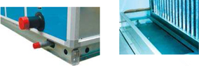
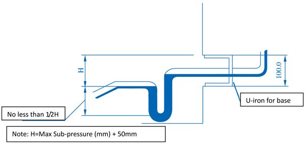
2、 Requirement for foundation of unit:
· The base for unit must design in accordance with length and width of unit, which shall level up horizontally.
· The foundation shall be above ground in order to install trap of condensed water. Please refer to the following picture:
3、When connecting pipes, please note:
· The working pressure of cold water pipe coil and hot water pipe coil in design shall be 1.6Mpa.
· The maximum pressure of steam pipe coil is no more than 1.4MPa.
4、As for fresh-air unit, when temperature of fresh air is below 0°C,operator turn on device to warm up pipe coil and take other relevant measures before turn on the unit, in order to prevent unit from frozen and burst.
5、Flexible joint must be used in the connection section of fan outlet and air duct.
6、When stopping the unit and temperature of pipe coil is lower than freezing temperature, the water inside pipe shall be empty and all standing water shall be blown out. If standing water cannot blow empty, antifreeze shall be added in.
7、Insulation measures have been taken into consideration, the surface will not produce dews under normal conditions.
8、Please leave sufficient space for routine examination.
9、Temperature of supplied air shall not exceed 80°C, if so, user shall raise the requirement that high temperature bearings and special motor will be used.
10、If customer has special configuration, such as electric adjustable damper, copper header, stainless steel water pan, high efficient filter and other non-standard requirement, customer shall specify when ordering the purchase.
11、If customer needs other requirement such as silencing, secondary air return, purification, adjustment of frequency, recycling of energy, customer shall specify when ordering. Carrier will meet all those requirements. The steam pressure scope needed for humidifying dry steam ranges from 0.02-0.04Mpa.
29
