Exhibit 4.8.60 -Self-Control Components - Two-Way Valve - VVG41 Series
| SIEMENS | 4364 |
| Two-Way Valve | |
| External Thread Connection, PN16 | VVG44… |
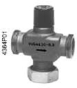
External thread connection G…B two-way valve, pressure grade PN16
| l | Valve body: bronze Rg5 |
| l | Nominal diameter: DN15…DN40mm (1/2’’…1 1/2’’) |
| l | Flow rate: kvs 0.25…25m3/h |
| l | Stroke of valve handle: 5.5 mm |
| l | Can be regulated manually by mounting a regulator |
| l | Can be mounted with the SQS35…, Sqs65… or SQS85…actuators. |
| l | Accessories can be ordered independently |
| Application Be applicable for the control valve or safety shutoff valves of small and medium-sized heating, ventilating and air conditioning system. Be applicable for closed system. | |
| Media | Cooling water | |
| Chilled water | ||
| Low temperature hot water | +2…+120℃ | |
| Anti-freezing water | ||
Siemens Building Technologies
CM1N4364C/03.2003
HVAC Products
1/6
Model overview
| Model | DN | kVS [m3/h] | Sv | △Pvmax. [kPa] | |
| [mm] | [Inch] | ||||
VVG44.15-0.25 VVG44.15-0.4 VVG44.15-0.63 | 15 | ½” | 0.25 0.4 0.63 | >50 | 400 |
| VVG44.15-1 | 1 1.6 2.5 4 | ||||
VVG44.15-1.6 VVG44.15-2.5 VVG44.15-4 | >100 | ||||
| VVG44.20-6.3 | 20 25 32 40 | ¾” 1” 1¼” 1½” | 6.3 10 16 25 | ||
VVG44.25-10 VVG44.32-16 VVG44.40-25 | 300 200 100 | ||||
DN= nominal diameter
kVS = rated flow that conforms to VDI 2173 Standard
Sv = flow capacity that conforms to VDI 2173 Standard
△P vmax..= maximum allowable differential pressure between two ends of valves, when the valve handle reaches the maximum stroke (the valve is fully open)
| Order | Please describe the quantity, product name and model code when ordering the purchase. |
For example: three two-way valves VVG44.25-10
The accessories must be ordered separately.
| Transportation | The valve, actuator and the required accessories are packaged and supplied separately. |
Combining equipment
| Valve model | H100 [mm] | Actuator SQS35…, SQS65…, SQS85… | Accessories Model | |
△Pmax | △Ps | |||
| [kPa] | ||||
VVG44.15-0.25 VVG44.15-0.4 VVG44.15-0.63 | 5.5 | 400 | 1600 | ALG15 |
VVG44.15-1 VVG44.15-1.6 | 850 | |||
VVG44.15-2.5 VVG44.15-4 | 400 | |||
| VVG44.20-6.3 | 800 400 225 100 | ALG20 ALG25 ALG32 ALG40 | ||
VVG44.25-10 VVG44.32-16 | 300 200 100 | |||
| VVG44.40-25 | ||||
| Technical data N4573 | ||||
Siemens Building Technologies
CM1N4364C/03.2003
HVAC Products
1/6
1) Optional actuator: ●AC 230V, three-position signal
● AC 24V, three-position signal
● AC 24V, DC 0…10 V or DC 2…10V scale position signal
H100 = 100% stroke of valve and actuator
△Pmax = maximum allowable differential pressure between both ends of valve, when the actuator can maintain normal operation within the whole stroke
△Ps = maximum allowable differential pressure (shut-off pressure) between both ends of valve, on the premise of ensuring the actuator can be closed safely
| Mechanical design | 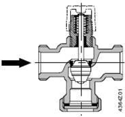 | |
| Valve profile | Pilot parabola valve plug and valve handle are integrated. | |
| Valve seat is attached to valve body through special seal material directly. |
| Note: | the two-way seat valve cannot be used as three-way valve by loosening the screw nut and removing the blank flange at the bottom of valve. |
| Disposal | Due to the use of different types of materials, before disposing, disassemble the nut of various models of material, and classify the valve parts. |
Siemens Building Technologies
CM1N4364C/03.2003
HVAC Products
1/6
Model selection
Flow rate graph
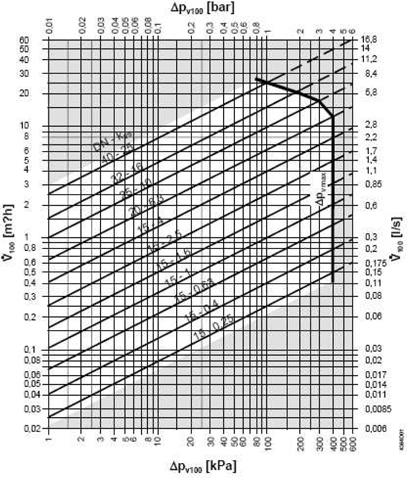
100 kPa = 1 bar ≈10 mWG
1 m3h = 0.278 Kg/s when the water is 20℃
△Pvmax. = maximum allowable differential pressure between both ends of valve, when the actuator can maintain normal operation within the whole stroke
△Pv100 = differential pressure between both ends of valve, when the valve is fully open and its flow is V100. Its unit is kPa or bar.
V100 = flow rate, with the unit of m3/h or l/s
Valve flow characteristics
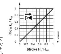 | |
| Valve flow characteristics | |
| Linear, comply with VDI/VDE2173 Standard | |
Notices
| Engineering | ● It is suggested that the valve be mounted on the return water pipe, because in the heating system, the temperature of return water pipe is relatively low. In this way, the service life of valve spool seal can be extended. |
● The water quality shall comply with VDI 2035 Standard. |
| Note | It is suggested that the filter be mounted in front of valve, so as to increase the operational reliability of valve. |
| Mounting | The valve and actuator can be assembled in the mounting position simply, independent of special tools and any adjustment. |
| The valve shall be attached with the Instruction for Mounting before leaving the factory. |
Mounting position
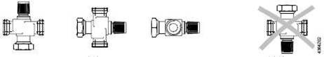
| Allowed | Forbidden |
| Direction of water flow | During the mounting, pay attention that the mark of water current direction on the valve shall be consistent with the |
| actual water current direction. |  |
| Debugging | Debug the valve with the hand operated regulating knob that has been mounted or with the actuator that is mounted directly. |
Valve handle contracts: flow increases
Valve handle extends: flow decreases
Siemens Building Technologies
CM1N4364C/03.2003
HVAC Products
1/6
| Repair | When repairing the actuator, comply with the following sequences: first turn off the water pump and cut off the water pump power source; close the stop valve, drain the water within the water pipe in order to reduce the pressure within water pipe, and cool the hot water pipe naturally. Remove the electrical wiring from connection terminal. |
| Re-debug the valve with the hand operated regulating knob mounted or the actuator mounted correctly. |
| Seal of valve handle | The valve handle seal cannot be replaced. If it leaks, the whole valve must be replaced. So, the attention must be paid to the information provided in the “Repair”. You can contact the local office or branch of Siemens Building Technologies. |
| Guarantee | The valves shall not be guaranteed if the actuator is manufactured the third manufacturer. |
All technical data listed, including△Pmax, △Ps, leakage rate, noise index and lifetime are only applicable to the corresponding actuators of Siemens Building Technologies included in the “Model overview”. |
| Technical data | ||||
| Functional parameter | PN (pressure) grade | PN16 | ||
| Valve flow characteristics | ||||
| 0…100% linear, comply with VDI / VDE 2173 Standard | ||||
| Leakage rate | kvs 0…0.02%, comply with VDI / VDE 2174 Standard | |||
| Allowable operating pressure | Within +2…+120, 1600KPa (16 bar), comply with ISO 7268 / EN 1333, DIN 4747 / DIN3158 Standards | |||
| Thread connection | ||||
| Valve | G…B, comply with ISO 228/1 Standard | |||
| Accessories | Rp…, comply with ISO 7/1 Standard | |||
| Stroke | 5.5 mm | |||
| Weight | See the “Dimension” (form) | |||
| Material | Valve body | Bronze G-CuSn5ZnPb (Rg5), comply with DIN 1705 Standard | ||
| Valve seat | Stainless steel, bronze Rg5 and brass | |||
| Stainless steel |
Siemens Building Technologies
CM1N4364C/03.2003
HVAC Products
1/6
| Valve plug | Stainless steel or brass | |||
| Seal ring | Brass | |||
| Seal material | EPDM-O ring | |||
| Accessory ALG | Malleable iron | |||
| Dimension | Unit of all dimensions: mm |
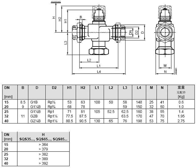
| DN = | nominal diameter |
| H = | total height of actuator plus minimum mounting space of mounting, connecting and operation, or the minimum distance required by maintenance to the ceiling or wall |
Siemens Building Technologies
CM1N4364C/03.2003
HVAC Products
1/6
| H1 = | distance from the center line of water pipe to the mounting edge (upper edge) of actuator |
| H2 = | position when the valve is fully open (it means the valve handle extends completely) |
Siemens Building Technologies
CM1N4364C/03.2003
HVAC Products
1/6